
Related Manuals for Grizzly G0453Z


Summary of Contents for Grizzly G0453Z
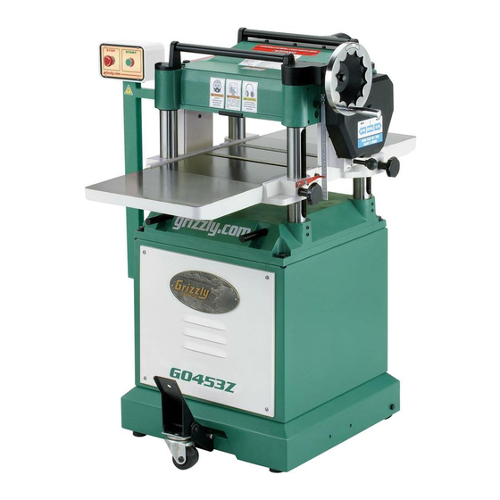
- Page 1 MODEL G0453Z/G0454Z 15" & 20" MOBILE PLANER w/SPIRAL CUTTERHEAD OWNER'S MANUAL WARNING: NO PORTION OF THIS MANUAL MAY BE REPRODUCED IN ANY SHAPE OR FORM WITHOUT THE WRITTEN APPROVAL OF GRIZZLY INDUSTRIAL, INC.
- Page 2 This manual provides critical safety instructions on the proper setup, operation, maintenance, and service of this machine/tool. Save this document, refer to it often, and use it to instruct other operators. Failure to read, understand and follow the instructions in this manual may result in fire or serious personal injury—including amputation, electrocution, or death.
-
Page 3: Table Of Contents
Table of Contents INTRODUCTION ..........2 SECTION 5: ACCESSORIES ......27 SECTION 6: MAINTENANCE ......28 SECTION 7: SERVICE ........31 SECTION 1: SAFETY ........9 SECTION 2: CIRCUIT REQUIREMENTS ..12 SECTION 3: SETUP ........13 SECTION 8: WIRING ........43 SECTION 9: PARTS ........ -
Page 4: Introduction
INTRODUCTION Manual Accuracy Contact Info your machine may not exactly match the manual Machine Description www.grizzly.com... - Page 5 If you have never used this type of machine or equipment before, WE STRONGLY RECOMMEND that you read books, review industry trade magazines, or get formal training before beginning any projects. Regardless of the content in this section, Grizzly Industrial will not be held liable for accidents caused by lack of training.
- Page 6 Internal Components Figure 2. A. Anti-Kickback Fingers: Pressure Bar: B. Serrated Infeed Roller: G. Outfeed Roller: C. Chip Breaker: H. Table Rollers: D. Chip Deflector: Planer Table: E. Cutterhead:...
- Page 7 G0453Z Machine Data Sheet Customer Service #: (570) 546-9663 · To Order Call: (800) 523-4777 · Fax #: (800) 438-5901 Weight................................655 lbs. Width (side-to-side) x Depth (front-to-back) x Height............... 32-1/2 x 42 x 45-7/8 in. Footprint (Length x Width)........................22-1/2 x 22 in. Type................................
- Page 8 Cutterhead Type............................Spiral Cutterhead Dia............................. 3 in. No. of Cutter Spirals............................4 No. of Indexable Cutters..........................74 Cutter Insert Type........................Indexable Carbide Cutter Insert Size Length......................... 14 mm Cutter Insert Size Width........................... 14 mm Cutter Insert Size Thickness........................2 mm Table Movement............................
- Page 9 G0454Z Machine Data Sheet Customer Service #: (570) 546-9663 · To Order Call: (800) 523-4777 · Fax #: (800) 438-5901 Weight................................783 lbs. Width (side-to-side) x Depth (front-to-back) x Height............... 39 x 55-5/8 x 45-7/8 in. Footprint (Length x Width)....................... 23-1/2 x 19-1/2 in. Type..................................
- Page 10 Cutterhead Type............................Spiral Cutterhead Dia............................3-1/8 in. No. of Cutter Spirals............................4 No. of Indexable Cutters..........................98 Cutter Insert Type........................Indexable Carbide Cutter Insert Size Length......................... 14 mm Cutter Insert Size Width........................... 14 mm Cutter Insert Size Thickness........................2 mm Table Movement............................
-
Page 11: Section 1: Safety
SECTION 1: SAFETY For Your Own Safety, Read Instruction Manual Before Operating this Machine The purpose of safety symbols is to attract your attention to possible hazardous conditions. This manual uses a series of symbols and signal words intended to convey the level of importance of the safety messages. -
Page 12: Safety Instructions For Machinery
Safety Instructions for Machinery DISCONNECTING POWER SUPPLY. APPROVED OPERATION. INTENDED USE. CHILDREN & BYSTANDERS. STABLE MACHINE. FEED DIRECTION. SECURING WORKPIECE. FORCING MACHINERY. UNATTENDED OPERATION. GUARDS & COVERS. MAINTENANCE & INSPECTION. REMOVING TOOLS. AWKWARD POSITIONS. EXPERIENCING DIFFICULTIES. DANGEROUS ENVIRONMENTS. -
Page 13: Additional Safety Instructions For Planers
Additional Safety Instructions for Planers OWNER'S MANUAL. LOOKING INSIDE PLANER. KICKBACK. CUTTING LIMITATIONS. Until you have a clear understand- ing of kickback and how it occurs, DO NOT Data Sheet operate this planer! Page 5 REACHING INSIDE PLANER. 10. CLEAN STOCK. DULL/DAMAGED INSERTS. -
Page 14: Section 2: Circuit Requirements
SECTION 2: CIRCUIT REQUIREMENTS Power Connection Device 220V Single-Phase Operation Figure 3 GROUNDED Serious personal injury could occur if you 6-20 RECEPTACLE connect the machine to power before com- pleting the setup process. DO NOT connect the machine to the power until instructed 6-20 PLUG later in this manual. -
Page 15: Section 3: Setup
SECTION 3: SETUP Needed for Setup This machine presents serious injury hazards to untrained users. Read through this entire manu- al to become familiar with Description the controls and opera- tions before starting the machine! Wear safety glasses dur- ing the entire setup pro- cess! Unpacking Model... - Page 16 G0454Z Hardware and Tools (not shown) Inventory Note: If you can't find an item on this list, check the mounting location on the machine or examine the packaging materials carefully. Occasionally we pre-install certain components for shipping purposes. Box Inventory: (Figure 4) G0453Z Hardware and Tools (not shown) Figure 4.
-
Page 17: Site Considerations
Clean Up Site Considerations Floor Load Machine Data Sheets Figure 5 Placement Location You MUST clean the cutterhead (remove the top cover), table, feed rollers, and the exten- sion wings before assembly to ensure proper operation of your planer. Figure 6 Gasoline and petroleum G0453Z products have low flash... - Page 18 Lifting & Moving Assembly Planer To assemble your planer: Figure 8 Model G0453Z/ G0454Z is a heavy machine. Serious per- sonal injury may occur if safe moving methods are not used. To be safe, get assistance and use power equipment to move the shipping crate and remove the machine from the crate.
- Page 19 Model G0454Z: Figure 11 Figure 9 Figure 11. Figure 9. Model G0453Z: Note: Tighten the hex bolt just enough for it Figure 10 to be snug without hampering the pivot action of the bracket Note: You will need to reach into the dust hood to hold the hex nuts while tightening the hex bolts.
-
Page 20: Dust Collection
To check the gearbox oil reservoir: Dust Collection Figure DO NOT operate the Model G0453Z/G0454Z without an adequate dust collection system. This planer creates substantial amounts of wood dust while operating. Failure to use a dust collection system can result in short and long-term respiratory illness. -
Page 21: Test Run
Test Run Figure 13 Figure 13. Troubleshooting Page 31 Feed Rate Page 24 Before starting the planer, make sure you have performed the preceding assembly and adjustment instructions, and you have read through the rest of the manual and are familiar with the various functions and safety features on this machine. - Page 22 Re-Tension V-Belts Recommended Adjustments V-Belts Page 35 SERVICE Page 31 Factory adjustments that should be verified: Page 37 Page 38 Page 38 Page 38 Page 41 Page 41...
-
Page 23: Section 4: Operations
E. Table Locks: OMMEND that you read books, review industry trade magazines, or get formal training before beginning any projects. Regardless of the content in this section, Grizzly Industrial will not be held liable for accidents caused by lack of training. -
Page 24: Operation Overview
Operation Overview Planing Tips Operation To complete a typical operation, the operator does the following:... -
Page 25: Workpiece Inspection
Workpiece Inspection Before cutting, inspect all workpieces for the following: Excessive Warping: Material Type: Minor Cupping: Foreign Objects:... -
Page 26: Wood Hardness
Wood Hardness Feed Rate NOTICE Only change the feed rate when the planer is running, but DO NOT attempt to change Figure 15 the feed rate during any cutting operations or damage to the gearbox will result. Note: The Janka Hardness Rating is expressed in pounds of force required to embed a 0.444"... -
Page 27: Depth Of Cut
Depth of Cut Bed Roller Height Figure 18 Figure 17 Figure 18. Figure 17. Accessories Page No list of safety guidelines can be complete. Every shop environment is different. Always consider safety first, as it applies to your individual working conditions. Use this and other machinery with caution and respect. - Page 28 NOTICE Bed rollers that are not adjusted to the cor- rect height or out of alignment with each other can cause poor finishes, inconsistent planing thickness, and other undesirable results. Tools Needed To adjust the bed rollers: Figure 19 Figure 19.
-
Page 29: Section 5: Accessories
SECTION 5: ACCESSORIES G1738—Rotacator™ Precision Planer Tool T21348—Carbide Indexable Inserts, 10 Pk. Figure 22. G1029Z—2HP Dust Collector Figure 20. G8983—Tilting Roller Stand G8984—Single Roller Stand G8985—5 Roller Stand Figure 23. Figure 21. -
Page 30: Section 6: Maintenance
SECTION 6: MAINTENANCE Every 160 Hours of Operation: Page Always disconnect power Page to the machine before performing maintenance. Failure to do this may Page 30 result in serious person- Page al injury. Schedule Yearly: Page 30 Cleaning & Protecting Note: This maintenance schedule is based on average daily usage. - Page 31 Columns and Leadscrews Lubrication NOTICE Figure 25 Failure to followed reasonable lubrication practices as instructed in this manual for your planer could lead to premature failure of your planer and will void the warranty. Parts Breakdowns Page 46 Page 28 Figure 25.
- Page 32 Table Height Chain & Sprockets Gearbox Oil Figure 27 Figures 29–30 Figure 27. Drive Chain & Sprockets Figure 29. Figure 28 Figure 30. Figure 28.
-
Page 33: Section 7: Service
SECTION 7: SERVICE Troubleshooting Motor & Electrical Pages 44–45 Page 35 Page 36 Pages 44–45... - Page 34 Motor & Electrical (continued) Page 25 Page 41 Machine Operation Page 25 Page 16 Page 38 Note: A small amount of snipe is inevitable with all types of planers—the key is to minimize it. Page 25 Page 25 Page 38 Page Page 23 Page 34...
- Page 35 Machine Operation (continued) Page 34 Page 34 Page 24 Page 38 Page 25 Page 34 Page 34 Page 24 Page 25 Page 41...
- Page 36 Rotating/Replacing Cutterhead Inserts Note: Proper cleaning of the insert, Torx screw, and the cutterhead pocket is critical to achieving a smooth finish. Dirt or dust trapped between the insert and cutterhead will slightly raise the insert, and make noticeable marks on your workpiece the next time you cut.
- Page 37 V-Belt Tensioning/ Replacement NOTICE After the first 16 hours of use, the V-belts will stretch and seat into the pulley grooves. The V-belts must be properly re-tensioned after this period to avoid severely reducing their useful life. Figure 32. Figure 32 Tools Needed Note: The V-belts are correctly tensioned when there is approximately...
-
Page 38: Pulley Alignment
Pulley Alignment Tools Needed Step 2 To check/re-align pulleys: Figure 34 Figure 34. - Page 39 Table Height Chain NOTICE Tension During the next step, DO NOT let the chain fall off the sprockets. It can be very difficult to return the chain to its proper location on the sprockets without changing the table adjustments. Note: The goal in the next step is to remove looseness in the chain without putting tension on it or the sprockets.
- Page 40 Using a Rotacator Feed Rollers, Chip Tools Needed Breaker & Pressure Bar Heights Page 27 Figure 37 Page 27 Dist. Below Cutterhead at BDC (Figure 36) Figure 37. Figure 36.
- Page 41 Step 5 Figure 38 Figure 39 Figure 39. 12. Model G0454Z Only: Step 12 Figure 38. Figure 40 Steps 6–7 Step 5 Steps 7–10 Figure 40.
- Page 42 Using Wood Blocks Tools Needed straight Note: Having the wood blocks at an even height is critical to the accuracy of your overall adjustments. For best results, make Steps 7–13 the 2x4 square with a jointer and table saw Using a Rotacator before cutting it in half.
-
Page 43: Roller Spring Tension
Roller Spring Positioning Chip Tension Deflector Tools Needed To adjust the chip deflector gap: Tools Needed To adjust the roller spring tension to factory recommendations: Figure 43 Figure 42 Figure 43. — Step 3 Figure 42. -
Page 44: Scale Calibration
Step 3 Anti-Kickback Fingers Scale Calibration Figure 45 Tools Needed To re-position the scale: Note: Turn the board over between each pass to make the surfaces parallel. Figure 45. Figure 44 Proper operation of the anti-kickback fin- gers is critical for the safe operation of this planer. -
Page 45: Section 8: Wiring
SHOCK HAZARD. MODIFICATIONS. MOTOR WIRING. QUALIFIED ELECTRICIAN. CAPACITORS. WIRE CONNECTIONS. CIRCUIT REQUIREMENTS. Page 12 WIRE/COMPONENT DAMAGE. EXPERIENCING DIFFICULTIES. The photos and diagrams included in this section are best viewed in color. You can view these pages in color at www.grizzly.com. - Page 46 G0453Z Wiring Diagram 220 VAC L6-20 PLUG (as recommended) CONTROL PANEL (from behind) MAGNETIC SWITCH ASSEMBLY MS1-09D 220V MOTOR READ ELECTRICAL SAFETY ON PAGE 43!
- Page 47 G0454Z Wiring Diagram 220 VAC L6-30 PLUG (as recommended) CONTROL PANEL (from behind) MAGNETIC SWITCH ASSEMBLY MS1-35D 220V MOTOR READ ELECTRICAL SAFETY ON PAGE 43!
-
Page 48: Section 9: Parts
SECTION 9: PARTS G0453Z Headstock Breakdown... - Page 49 G0453Z Headstock Parts List REF PART # DESCRIPTION REF PART # DESCRIPTION P0453Z001 HANDLE P0453Z060 CUT LIMIT PLATE PN09M HEX NUT M12-1.75 PS03M PHLP HD SCR M6-1 X 8 PW06M FLAT WASHER 12MM P0453Z062 HEAD CASTING P0453Z004 HANDWHEEL LABEL P0453Z063 OUTFEED ROLLER P0453Z005 HANDWHEEL...
- Page 50 G0453Z Table REF PART # DESCRIPTION REF PART # DESCRIPTION P0453Z201 TABLE/BED P0453Z208 LOCK BAR P0453Z202 ROLLER P0453Z209 FEMALE KNOB M12-1.75 P80018 BALL BEARING 80018 P0453Z210 EXTENSION WING P0453Z204 ECCENTRIC SHAFT PLW04M LOCK WASHER 8MM PSS11M SET SCREW M6-1 X 16 PW01M FLAT WASHER 8MM P0453Z206...
- Page 51 G0453Z Columns REF PART # DESCRIPTION REF PART # DESCRIPTION P0453Z301 BASE PK69M KEY 4 X 4 X 12 PB24M HEX BOLT M12-1.75 X 45 PR03M EXT RETAINING RING 12MM PN09M HEX NUT M12-1.75 P0453Z319 SPROCKET PW06M FLAT WASHER 12MM PK08M KEY 5 X 5 X 16 P0453Z305...
- Page 52 G0453Z Gearbox REF PART # DESCRIPTION REF PART # DESCRIPTION P0453Z401 GEAR BOX COVER PW03M FLAT WASHER 6MM PB10M HEX BOLT M6-1 X 25 P0453Z423 COMPRESSION SPRING P0453Z403 COLUMN SPROCKET P0453Z424 STEEL BALL 4MM PW01M FLAT WASHER 8MM P0453Z425 GEAR ( C) PB03M HEX BOLT M8-1.25 X 16 PK36M...
- Page 53 G0453Z Stand Breakdown...
- Page 54 G0453Z Stand Parts List PART # DESCRIPTION PART # DESCRIPTION P0453Z501 ENCLOSED STAND P0453Z534 SPECIAL HEX NUT M8-1.25 P0453Z502 BACK COVER PN02M HEX NUT M10-1.5 P0453Z503 FRONT COVER PW04M FLAT WASHER 10MM PS107M PHLP HD SCR M6-1 X 20 PB45M HEX BOLT M8-1.25 X 100 P0453Z505 MOTOR PLATE...
- Page 55 MUST maintain the original location and readability of the labels on the machine. If any label is removed or becomes unreadable, REPLACE that label before using the machine again. Contact Grizzly at (800) 523-4777 or www.grizzly.com to order new labels.
- Page 56 G0454Z Headstock Breakdown...
- Page 57 G0454Z Headstock Parts List REF PART # DESCRIPTION REF PART # DESCRIPTION P0453Z001 HANDLE PK129M KEY 8 X 8 X 36 PN09M HEX NUT M12-1.75 P6206 BALL BEARING 6206ZZ PW06M FLAT WASHER 12MM PB83M HEX BOLT M6-1 X 16 P0453Z005 HANDWHEEL PW03M FLAT WASHER 6MM...
- Page 58 G0454Z Headstock Parts List REF PART # DESCRIPTION REF PART # DESCRIPTION P0454Z097 CHAIN 06B-1 X 67 P0454Z108 SPECIAL BOLT PK01M KEY 5 X 5 X 22 PW01M FLAT WASHER 8MM P0454Z099 INFEED ROLLER PN03M HEX NUT M8-1.25 PW03M FLAT WASHER 6MM PVMX60 COGGED V-BELT MX-60 PB02M...
- Page 59 G0454Z Table REF PART # DESCRIPTION REF PART # DESCRIPTION P0454Z201 TABLE/BED P0453Z208 LOCK BAR P0454Z202 ROLLER P0453Z209 FEMALE KNOB M12-1.75 P6201 BALL BEARING 6201ZZ P0454Z210 EXTENSION WING P0454Z204 ECCENTRIC SHAFT PLW04M LOCK WASHER 8MM PSS04M SET SCREW M6-1 X 12 PW01M FLAT WASHER 8MM P0453Z206...
- Page 60 G0454Z Columns REF PART # DESCRIPTION REF PART # DESCRIPTION P0454Z301 BASE PR03M EXT RETAINING RING 12MM PB38M HEX BOLT M12-1.75 X 60 P0454Z319 TABLE LIFTING SPROCKET PN09M HEX NUT M12-1.75 PK08M KEY 5 X 5 X 16 PW06M FLAT WASHER 12MM PW04M FLAT WASHER 10MM P0454Z305...
- Page 61 G0454Z Gearbox REF PART # DESCRIPTION REF PART # DESCRIPTION P0454Z401 GEAR BOX COVER PW03M FLAT WASHER 6MM PSB06M CAP SCREW M6-1 X 25 P0453Z423 COMPRESSION SPRING P0454Z403 GEARBOX SPROCKET P0453Z424 STEEL BALL 4MM PW01M FLAT WASHER 8MM P0454Z425 GEAR (C) PB03M HEX BOLT M8-1.25 X 16 PK36M...
- Page 62 G0454Z Stand Breakdown...
- Page 63 G0454Z Stand Parts List REF PART # DESCRIPTION REF PART # DESCRIPTION P0454Z501 ENCLOSED STAND P0453Z534 SPECIAL HEX NUT M8-1.25 P0454Z502 BACK COVER PN02M HEX NUT M10-1.5 PFH06M FLAT HD SCR M6-1 X 20 PW04M FLAT WASHER 10MM P0454Z504 MOTOR PLATE PB45M HEX BOLT M8-1.25 X 100 PSS04M...
- Page 64 MUST maintain the original location and readability of the labels on the machine. If any label is removed or becomes unreadable, REPLACE that label before using the machine again. Contact Grizzly at (800) 523-4777 or www.grizzly.com to order new labels.
-
Page 65: Warranty Card
WARRANTY CARD The following information is given on a voluntary basis. It will be used for marketing purposes to help us develop better products and services. Of course, all information is strictly confidential. Note: We never use names more than 3 times. _____________________________________________________________________ _________________________________________________________________________________ _________________________________________________________________________________... -
Page 67: Warranty And Returns
WARRANTY AND RETURNS... - Page 68 ® Buy Direct and Save with Grizzly – Trusted, Proven and a Great Value! ~Since 1983~ Visit Our Website Today For Current Specials! ORDER 24 HOURS A DAY! 1-800-523-4777...
Need help?
Do you have a question about the G0453Z and is the answer not in the manual?
Questions and answers