Table of Contents
Advertisement
Quick Links
INTRODUCTION
The Model G1033Z is the same planer as the
Model G1033 with the upgrade of the chromed
3-roller extension rollers and 5 HP motor.
INVENTORY
1.
Planer Unit .................................................. 1
2.
Dust Hood .................................................. 1
3.
Starter Switch Assembly ............................ 1
4.
Table Extension Roller Assembly .............. 2
5.
Handwheel ................................................. 1
6.
Handwheel Handle ..................................... 1
6.
Hardware Bag :
— Hex Bolt M6-1 x 12 ................................. 6
— Flat Washer 6mm ................................... 6
— Hex Bolt M10-1.5 x 25 ............................ 8
— Flat Washer 1/2" ..................................... 8
— Knife Setting Rod .................................... 1
— Knife Setting Gauge ............................... 2
— E-Clip Ring 9mm ..................................... 4
—Hex Nut M12-1.75 .................................. 1
—Flat Washer 12mm ................................. 1
—Direction Label ........................................ 1
— Allen Wrench 3mm ................................. 1
— Allen Wrench 4mm ................................ 1
— Allen Wrench 5mm ................................. 1
— Allen Wrench 6mm ................................. 1
— Open End Wrench 8/10mm .................... 1
— Open End Wrench 12/14mm .................. 1
— Open End Wrench 17/19mm .................. 1
RECOMMENDED FOR SETUP
G1738—Rotacator™ Precision Planer Tool
The Rotacator is a dial indicator on a magnetic
base designed for quickly and accurately setting
the critical tolerances needed when adjusting
planers to avoid chattered cuts.
Helps adjust infeed/outfeed rollers, pressure bars,
chip breakers, and bed rollers. Also a great setup
tool for other machines! Accurate to 0.001".
Indicator rotates 360˚.
MANUAL INSERT
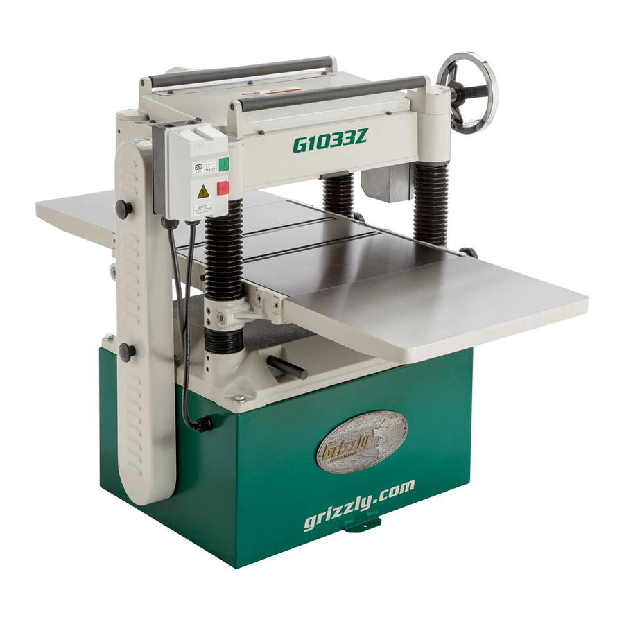
Model G1033Z
20" 5 HP Planer
Figure 1. Model G1033Z.
Figure 2. Rotacator™ Precision Planer Tool is
an important tool for setting up your planer for
the highest quality results.
Advertisement
Table of Contents

Related Manuals for Grizzly G1033Z


Summary of Contents for Grizzly G1033Z
- Page 1 INTRODUCTION The Model G1033Z is the same planer as the Model G1033 with the upgrade of the chromed 3-roller extension rollers and 5 HP motor. INVENTORY Planer Unit ... 1 Dust Hood ... 1 Starter Switch Assembly ... 1 Table Extension Roller Assembly ... 2 Handwheel ...
- Page 2 PB02M HEX BOLT M6-1 X 12 COPYRIGHT © MARCH, 2005. BY GRIZZLY INDUSTRIAL, INC. WARNING: NO PORTION OF THIS MANUAL MAY BE REPRODUCED IN ANY SHAPE OR FORM WITHOUT THE WRITTEN APPROVAL OF GRIZZLY INDUSTRIAL, INC. �� �� �� �����...
- Page 3 20'' PLANER MODEL G1033 INSTRUCTION MANUAL COPYRIGHT © 1990 BY GRIZZLY INDUSTRIAL, INC. WARNING: NO PORTION OF THIS MANUAL MAY BE REPRODUCED IN ANY SHAPE OR FORM WITHOUT THE WRITTEN APPROVAL OF GRIZZLY INDUSTRIAL, INC. REVISED APRIL, 1999. PRINTED IN U.S.A.
-
Page 5: Table Of Contents
GENERAL ...23 KNIVES ...23 LUBRICATION...24 BELT TENSION ...25 BELT ALIGNMENT ...25 CLOSURE MACHINE DATA ...27 TROUBLESHOOTING...28 PARTS BREAKDOWN AND PARTS LISTS ...29-35 ADJUSTMENT BLOCK PATTERN ...36 WIRING DIAGRAM ...37 WARRANTY AND RETURNS ...38 G1033 20" Planer Table Of Contents PAGE... -
Page 6: Safety Instructions For Power Tools
G1033 20" Planer VISITORS... - Page 7 12. SECURE WORK. Use clamps or a vise to hold work when practical. It’s safer than using your hand and frees both hands to operate tool. G1033 20" Planer 13. DON’T OVERREACH. Keep proper foot- 14. MAINTAIN TOOLS WITH CARE. Keep 15. DISCONNECT TOOLS before servicing 16.
-
Page 8: Additional Safety Instructions For Planers
Never position fingers or thumbs near the infeed roller. Long stock should always be fully support- ed by some type of support fixture. Do not operate planer with dull or damaged knives. Ensure that the planer is properly adjusted before using. -
Page 9: Section 2: Circuit Requirements
SECTION 2: CIRCUIT REQUIREMENTS 220V Operation The 3 HP G1033 Planer motor is wired to oper- ate at 220V only. A 220V plug that matches your 220V receptacle must attach to the end of the power cord. Plugs and receptacles can be pur- chased at your local hardware store or home center. -
Page 10: Introduction Commentary
However, owing to Grizzly’s policy of con- tinuous improvement, changes may be made at any time with no obligation on the part of Grizzly. Whenever possible, though, we send manual updates to all owners of a particular tool or machine. -
Page 11: Unpacking
Unpacking This planer is shipped from the factory in a care- fully packed carton. If you find the machine to be damaged after you’ve signed for delivery and the truck and driver are already gone, you will need to file a freight claim with the carrier. Save the containers and all packing materials for inspec- tion by the carrier or their agent. -
Page 12: Clean Up
Failure to do so could result in injury. Site Considerations FLOOR LOAD Your G1033 Planer represents a large weight load in a small footprint. Most commercial floors are suitable for the Model G1033. Some residen- tial floors may require additional build up to sup- port both machine and operator. -
Page 13: Section 4: Assembly
SECTION 4: ASSEMBLY Overview Most of your G1033 Planer has been assembled at the factory, but some parts must be assembled or installed after delivery. We have organized the assembly process into steps. Please follow along in the order presented here. -
Page 14: Dust Hood
-10- Switch The magnetic ON/OFF switch supplied with the Planer is pre-wired to the motor. The remaining step requires connecting the switch to the plan- er's head casting. To attach the switch: 1. Align the holes on the flanges at the back of the switch box with the tapped holes on the front left corner of the head casting. -
Page 15: Knife Setting Jig
3. Snap the other E-clip onto the notch at the other end of the knife setting jig rod. Planer knives are dangerously sharp. Use extreme caution when working near cutting surfaces. Failure to exercise care while working near knives could result in severe injury. -
Page 16: Table Adjustment
.016'' (use a feeler gauge to determine gap) you will need to adjust the chain drive. See Figure 8. Figure 8. Measurement block in place. G1033 20" Planer... -
Page 17: Chain Drive
5. If the table is too high at the right side, rotate the sprockets in the opposite direc- tion. G1033 20" Planer Figure 9. Using block to align cutterhead. When you get the tolerance to within the .016'' range, micro-adjust by loosening the Allen head... -
Page 18: Bed Rollers
4. Once your roller heights are corrected, re- tighten the setscrews. 5. Spin the rollers and inspect for free move- ment. Planer knives are dangerously sharp. Use extreme caution when working near cutting surfaces. Failure to exercise care while working near knives could result in severe injury. -
Page 19: Knife Inspection
Knife Inspection The G1033 20" Planer comes equipped with a 4- knife cutterhead. The knives must be periodically replaced or adjusted. Adjustments should be as precise as possible with tolerances within ±.001'' to prolong the sharpness of the knife edges. -
Page 20: Feed Roller Speed
Feed Roller Speed The infeed and outfeed rollers power the stock through the planer. They keep boards flat and provide smooth movement. The power feed fea- tures two feed rates - 16 FPM and 20 FPM. The speed can be changed by moving the feed con- trol knob when the machine is running. -
Page 21: Spring Tension
To adjust roller spring tension: 1. Locate the four adjustment screws located on the top of the planer. See Figure 19. 2. Adjust screws #1 - #3 so that they protrude ⁄ " above the head casting. -
Page 22: Chipbreaker
(including snipe and board lines) can result. A pressure bar set too low can also place excess load on the planer’s motor. The pressure bar should be adjusted along with the infeed and out- feed rollers. To adjust the pressure bar: 1. -
Page 23: Chip Deflector
Proper tensioner adjust- ment is crucial to your planer’s operation. Not only will it have a direct effect on the quality of your work, incorrect tension on the drive chain may cause the rollers to jam, or cause the chain to break. -
Page 24: Scale Adjustment
2. Move the table to ⁄ '' under the thickness of your lumber and feed your test board through the planer. 3. Turn the handwheel one full rotation and run the board through once more. Turn the board over and repeat. -
Page 25: Section 6: Operations
Remember, wood stacked on a concrete floor can have small pieces of stone or concrete pressed into the wood. 2. Use the full width of the planer. Alternate between the left, the right and the middle when feeding lumber into the planer. Your knives will remain sharp much longer. -
Page 26: Wood Characteristics
Chatter marks can also be caused by running a narrow wood piece through the planer at either the right or left end of the cutterhead. Chatter, like uneven knife marks, will show in the form of a ''washboard'' look. -
Page 27: Knife Sharpening
This planer has knives with a grind angle of 45˚ which is a configuration which should suit most general planing needs. The optimal grind or bevel... -
Page 28: Lubrication
If the bad bearing is not replaced, it will eventually seize - possibly doing damage to other parts of the machine. Bearings are standard sizes and can be replaced through Grizzly. Proper lubrication of other components of the Model G1033 are essential for long life and trou- ble-free operation. -
Page 29: Belt Tension
Belt Tension Inspect the belts daily for the first couple of weeks you operate the planer. This is the time that the majority of stretching will occur. Adjust belt tension by lowering the motor down slightly. See Figure 27. Establish a periodic schedule of inspection. -
Page 30: Section 8: Closure
Model G1033 Planer. If you need parts or help in assembling your machine, or if you need operational information, we encourage you to call the Grizzly Industrial Service Department. Our trained service techni- cians will be glad to help you. -
Page 31: Machine Data
Customer Service #: (570) 326-3806 • To Order Call: (800) 523-4777 • Fax #: (800) 438-5901 GRIZZLY MODEL G1033 20" PLANER Design Type ... Floor Model Overall Dimensions: Table Size ...25 Height ...41" Overall Depth ...39" Overall Width ...58" Shipping Weight ...770 lbs. -
Page 32: Troubleshooting
TROUBLESHOOTING This section covers the most common processing problems encountered in planing and what to do about them. Do not make any adjustments until planer is unplugged and moving parts have come to a complete stop. SYMPTOM POSSIBLE CAUSE Motor will not start. - Page 34 PART # DESCRIPTION P1033001 HEADCASTING PSS13M SETSCREW M10-1.5 X 12 P1033003 CUTTERHEAD P1021103 SPRING P1033005 BLADES FOR PLANER P1033006 PB17M HEX BOLT M8-1.25 X 10 P1021166 KNIFE GAUGE W/BAR P6206 BEARING 6206 PK09M KEY 8 X 8 X 36 P1021007...
- Page 35 BEARING 6201 P1033204 ECCENTRIC SHAFT PSS04M SETSCREW M6-1.0X12 P1021143 THREADED GIB P1033207 LOCK ROD P1021146 P1021145 KNOB G1033 20" Planer PART # DESCRIPTION PSB14M CAP SCREW M10-1.25X20 P1033211 EXT ROLLER BAR P1033212 EXTENSION ROLLER PB32M HEX BOLT M10-1.5X25 PW04M FLAT WASHER 10MM...
- Page 36 REF PART # DESCRIPTION P1033301 BASE PSS13M SETSCREW M10-1.5 X 12 P1033303 COLUMN P1033304 COLUMN P1033305 LEADSCREW P1033306 LEADSCREW P1033307 LEADSCREW NUT P1033308 BUSHING PR22M INT RETAINING RING 38MM PK10M KEY 5 X5 X 12 P1033311 GEAR PR03M SNAP RING 12MM P6202 BALL BEARING 6202 PR21M...
- Page 37 PART # DESCRIPTION P1033401 STAND P1033402 COVER PFH06M FLAT HD SCREW M6-1.0 X 20 P1033404 P1033405 MOTOR MOUNT PSS20M SETSCREW M8-1.25 X 8 P1033407 COLLAR P1033408 ADJUSTABLE BOLT PN09M HEX NUT M12-1.75 PW01 FLAT WASHER PB07M HEX BOLT M8-1.25 X 25 P1033412 WASHER ⁄...
- Page 38 KEY 5 X 5 X 23 CHAIN, 25 LINKS HEX BOLT M6-1.0 X 15 SHIFTER SHIFTING SHAFT HANDLE FLAT WASHER 6MM HEX BOLT M6-1.0X12 O-RING 12MM KNOB GASKET GEAR CASE CAP SCREW M6-1.0X25 OIL PLUG CAP SCREW M8-1.25X50 G1033 20" Planer...
- Page 39 P1021149 SPROCKET PRP07M ROLL PIN 6X20 P1033091 CHAIN 33 LINKS PSB04M CAP SCREW M6-1.0 X 10 P1033099 CHAIN TENSIONER P1033102 SHAFT G1033 20" Planer " X " PART # DESCRIPTION P1033103 HANGER P1033104 SPRING P1033105 SPACER P1033106 OUTER CHAIN TENSIONER...
-
Page 40: Adjustment Block Pattern
-36- G1033 20" Planer... -
Page 41: Wiring Diagram
SWITCH G1033 20" Planer G1033 Wiring Diagram -Taian Type SINGLE PHASE 220 VOLT POWER SOURCE 5L3 13NO 6T3 14NO 2T1 4T2 TRIP IND. MANUAL RESET AUTO RESET TEST RESET MOTOR TERMINAL BOX Gray Black GROUND -37-... -
Page 42: Warranty And Returns
WARRANTY AND RETURNS Grizzly Industrial, Inc. warrants every product it sells for a period of 1 year to the original purchaser from the date of purchase. This warranty does not apply to defects due directly or indirectly to misuse, abuse, negligence, accidents, repairs or alterations or lack of maintenance. -
Page 43: Warranty Card
Do you think your purchase represents good value? ___Yes Would you recommend Grizzly Imports to a friend? ___Yes Would you allow us to use your name as a reference for Grizzly customers in your area? Note: We never use names more than three times. ___Yes Comments:_________________________________________________... - Page 44 FOLD ALONG DOTTED LINE FOLD ALONG DOTTED LINE Send a Grizzly Catalog to a friend: Name_______________________________ Street_______________________________ City______________State______Zip______ GRIZZLY INDUSTRIAL, INC. P.O. BOX 2069 BELLINGHAM, WA 98227-2069 TAPE ALONG EDGES--PLEASE DO NOT STAPLE Place Stamp Here...
Need help?
Do you have a question about the G1033Z and is the answer not in the manual?
Questions and answers