Table of Contents
Advertisement
Quick Links
Advertisement
Table of Contents

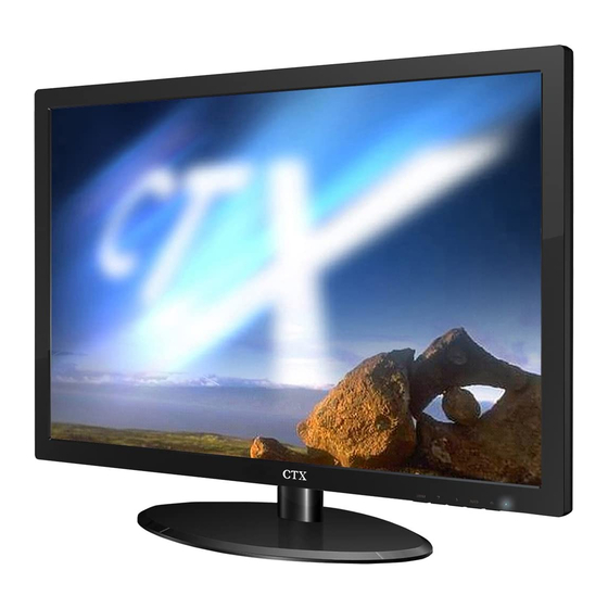
Summary of Contents for CTX E22M5G
- Page 1 User Manual M Series L E D B A C K L I G H T M o n i to r...
-
Page 2: Table Of Contents
Content F.C.C STATEMENT ⁄ IMPORTANT SAFEGUARDS 1. Introduction 1.1 Features......................6 1.2 Checking List....................6 2. Installation 2.1 Install the Pedestal..................7 2.2 Connect Your Monitor to Computer.............7 3. Front Panel overview 4. Access Features 4.1 Switching the Monitor On/Off...............9 4.2 Power Indicator..................9 4.3 Menu Features..................9 4.4 OSD Functional Control Description.............10 4.5 Preset Modes Timing Chart..............12... - Page 3 F.C.C STATEMENT FEDERAL COMMUNICATIONS COMMISSION This equipment has been tested and found to comply with the limits of a Class B digital device, pursuant to Part 15 of the FCC Rules. These limits are designed to provide reasonable protection against harmful interference in a residential installation.
-
Page 4: Important Safeguards
IMPORTANT SAFEGUARDS Warnings: Read all of these instructions Save these instructions for later use, please. Unplug this monitor from the wall outlet before cleaning. Do not use liquid cleaners or aerosol cleaners. Use a damp cloth for cleaning. Do not use attachments not recommended by the monitor manufacturer as they may cause hazards. - Page 5 0.Do not overload wall outlets and extension cords as this can result into fire or electric shock. 1.Never push objects of any kind into this monitor through cabinet slots as they may touch dangerous voltage points or short out parts that could result in a fire or electric shock.
-
Page 6: Introduction
1. Introduction 1.1 Features. ►Microprocessor based with OSD (On Screen Display) control. ►Compatible with standard IBM VGA, extended VGA, super VGA, IBM XGA, SXGA modes, as well as VESA resolution standards. ►Universal power supply 100-240 Vac, 50/60Hz(Power box)/DC 12V(Monitor) ►Microsoft Windows 95/98/2000/XP/VISTA/WIN7 compatible & VESA Display 1.2 Checking List Please make sure the following items are included with your LCD monitor:... -
Page 7: Installation
2. Installation To attach the base to your monitor, please follow the steps for installation of the pedestal as below: 2.2 Connect Your Monitor to Computer Turn off the computer and unplug the power cable. Connect the signal cable to the signal port on the back of the computer. -
Page 8: Front Panel Overview
3. Front Panel Overview ① Menu Button To push menu button turns on the menu, and it activates the items you highlight. ② Select Button(▲UP/▼DOWN) To choose which function you need. You may choose DOWN counterclockwise or UP clockwise. ③ Auto Button Auto adjusts the display mode to its utmost performance according to VGA setting. -
Page 9: Access Features
4. Access Features 4.1 SWITCHING THE MONITOR ON/OFF This power button is used for switching the monitor on and off. Note: The power button does not disconnect the device from the mains voltage. To completely disconnect the mains voltage. Please remove the power plug from the socket. -
Page 10: Osd Functional Control Description
4.4 OSD Functional Control Description 1. Main Menu OSD main menu of controls gives you an overview of the selection of controls available. When you want to make adjustment of the screen image, press and release button Menu 2. OSD Adjustment/ You can choose where you would like OSD image to appear on your screen. - Page 11 6. Color Select/ Color Select Menu Select User Mode User color you can adjust to individual color gum intensity by yourself. Increase or decrease red, green or blue depending upon which color is selected. 60.0 Cool: This control adjusts the color temperature of the screen image.
-
Page 12: Preset Modes Timing Chart
4.5 Preset Modes Timing Chart The screen image has been optimized during manufacture for the display modes listed below. 1. Aspect ratio 16:10 NOTE: All preset Item DotXLine Refreshr ate(Hz) modes are subject to change without 720X400 notice. 60,75 640X480 19"w: Items 1~6;... -
Page 13: Plug And Play
4.6 Plug and Play This monitor features the VESA DDC (Display Data Channel) standard, which when used with a DDC compatible video card, will simplify the monitor's set up. With VESA DDC 1/2B, when the monitor is powered up, it will automatically notify a windows 9X/2000/XP host computer of its scanning... -
Page 14: Technical Information
5. Technical 5.1 D-SUB Signal connector pin assignment Signal (D-sub) Signal (D-sub) 5 VDC Green Ground Blue Ground Ground SDA (For DDC) Self Test H. Sync. Red Ground V. Sync. Green Ground SCL (For DDC) Blue Ground D-SUB connector DVI-D Signal connector pin assignment (Optional) Signal (DVI) Signal (DVI) TMDS Data 2-... - Page 15 HDMI Signal connector pin assignment (Optional) Signal Signal TMDS data2+ TMDS clock shield TMDS data2 Shield TMDS clock- TMDS data2- TMDS data1+ Reserved(N.C on device) TMDS data1 Shield TMDS data1- TMDS data0+ DDC/CEC Ground TMDS data0 Shield +5V Power TMDS data0- Hot Plug Detect TMDS clock+ HDMI Type A signal connector...
-
Page 16: Visual Inspection
5.2 Visual Inspection Permanently unlit or lit pixels The standard of production techniques today cannot guarantee an absolutely faultfree screen display. A few isolated constant lit or unlit pixels may be present. The maximum permitted number of pixels faults is stipulated in the stringent international standard ISO-9241-302 (Class II). - Page 17 ww w. ct x. co m .t w www.ctxtec.co.uk ww w. ct xme . c o m All Right Reserved by Chuntex Electronic Co., Ltd.


Need help?
Do you have a question about the E22M5G and is the answer not in the manual?
Questions and answers