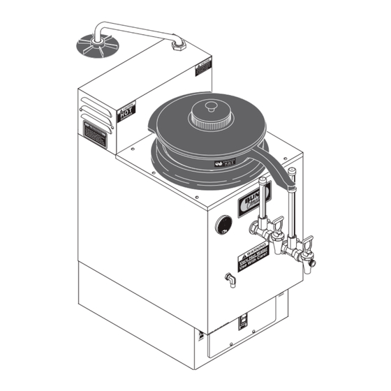
Bunn SRU Operating & Service Manual
Coffee brewer
Hide thumbs
Also See for SRU:
- Illustrated parts catalog (27 pages) ,
- Installation & operating manual (9 pages) ,
- Installation and operating manual (16 pages)
Table of Contents
Advertisement
SRU
SRUA
OPERATING & SERVICE MANUAL
BUNN-O-MATIC CORPORATION
POST OFFICE BOX 3227
SPRINGFIELD, ILLINOIS 62708-3227
PHONE: (217) 529-6601
FAX: (217) 529-6644
To ensure you have the latest revision of the Operating Manual, or to view the Illustrated Parts
Catalog, Programming Manual, or Service Manual, please visit the Bunn-O-Matic website, at
www.bunn.com. This is absolutely FREE, and the quickest way to obtain the latest catalog and
manual updates. For Technical Service, contact Bunn-O-Matic Corporation at 1-800-286-6070.
10067.0000J 10/08 ©1981 Bunn-O-Matic Corporation
Advertisement
Table of Contents

Related Manuals for Bunn SRU


Summary of Contents for Bunn SRU
- Page 1 To ensure you have the latest revision of the Operating Manual, or to view the Illustrated Parts Catalog, Programming Manual, or Service Manual, please visit the Bunn-O-Matic website, at www.bunn.com. This is absolutely FREE, and the quickest way to obtain the latest catalog and manual updates. For Technical Service, contact Bunn-O-Matic Corporation at 1-800-286-6070.
- Page 2 SOLE OPTION AS SPECIFIED HEREIN, TO REPAIR, REPLACEMENT OR REFUND. In no event shall BUNN be liable for any other damage or loss, including, but not limited to, lost profits, lost sales, loss of use of equipment, claims of Buyer’s customers, cost of capital, cost of down time, cost of substitute equipment, facilities or services, or any other special, incidental or consequential damages.
- Page 3 DAMAGE, FIRE, OR SHOCK HAZARD READ THE ENTIRE OPERATING MANUAL BEFORE BUYING OR USING THIS PRODUCT THIS APPLIANCE IS HEATED WHENEVER CONNECTED TO A POWER SOURCE 00831.0000F 3/98 ©1998 BUNN-O-MATIC CORPORATION #00831.0000 #37881.0000 ATTENTION: TURN OFF WHEN UNATTENDED WARNING #00878.0000...
- Page 4 GREEN GREEN L1 BLACK P1842 P1842 P1841 SRU Model requires 3-wire, SRUA Models require 2-wire, SRUA-CE Models require 2- grounded service rated 120/208 or grounded service rated 208 or 240 wire, grounded service rated 230 120/240 volts ac, 30 amp, single phase,...
- Page 5 The water inlet fitting is 3/8" flare. NOTE - Bunn-O-Matic recommends 3/8" copper tubing for installations from the 1/2" water supply line. Bunn- O-Matic does not recommend the use of a saddle valve to install the brewer. The size and shape of the hole made in the supply line by this type of device may restrict water flow.
- Page 6 11. Adjust the brew timer as required. See Adjusting Brew Volumes. Repeat steps 9 & 10. 12. The brewer is now properly adjusted to brew coffee. Bunn-O-Matic recommends a bead of silicon sealant be placed around the base on the countertop after the initial operation instructions are completed. B.O.M. #M2509.1001 sealant is available.
- Page 7 Whenever the pointer is in the green, brewer is ready for brewing. 2. Insert Bunn filter in funnel and add desired amount of coffee. 3. Level the bed of coffee and place funnel into the funnel support. Place funnel cover over the funnel and be sure the water swing spout is over the center of the funnel cover.
- Page 8 CAUTION - CLEANING SURFACES ARE HOT!! FILTER HOLDER A filter holder is supplied with each SRU coffee brewer. Its purpose is to keep the filters in their originally formed shape to properly fit the brewer funnel. It is suggested that only one cluster of filters be placed in the holder at one time for best results.
- Page 9 TROUBLESHOOTING A troubleshooting guide is provided to suggest probable causes and remedies for the most likely problems encountered. If the problem remains after exhausting the troubleshooting steps, contact the Bunn-O-Matic Technical Service Department. • Inspection, testing, and repair of electrical equipment should be performed only by qualified service person- nel.
- Page 10 TROUBLESHOOTING (cont.) REMEDY PROBLEM PROBABLE CAUSE Be sure water shut-off valve is open Brew cycle will not start (cont) 3. Water level below pump housing. and that the in-line filters or strainers (Water level in the hot water gauge are not blocking water flow. (Do not glass should be approximately half confuse water shut-off valve with the full).
- Page 11 Refer to Service - Limit Thermostat CAUTION - Do not eliminate or for testing procedures. See page bypass limit thermostat. Use only Bunn-O-Matic replacement part #29329.1000. 2. Control Thermostat Refer to Service - Control Ther- mostat for testing procedures. See page 18 3.
- Page 12 Remove swing spout and insert pump tubing. deliming rod down into pump tubing as far as possible. Funnel overflows 1. Filters Use Bunn filters made for the SRU ® brewer. 2. Hole in bottom of funnel Remove obstruction. obstructed. 3. Pump - Flow Rate Check pump flow rate with a watch.
- Page 13 TROUBLESHOOTING (cont.) PROBLEM PROBABLE CAUSE REMEDY When using a water softener, a Funnel overflows (cont.) 4. Soft Water coarse grind of coffee may be pre- ferred. If required, a bypass system is available as an optional feature. Be sure coffee reservoir is empty Coffee reservoir overflows 1.
-
Page 14: Table Of Contents
SERVICE Contents Circuit Breaker .............15 This section provides procedures for testing and Contactor ..............16 replacing various major components used in this Control Thermostat ..........18 brewer should service become necessary. Refer to Fuse and Fuse Holder ...........19 Troubleshooting for assistance in determining the Limit Thermostat ...........20 cause of any problem. -
Page 15: Circuit Breaker
SERVICE (cont.) If continuity is not present as described, press the reset CIRCUIT BREAKER (120/208V and 120/240V Three button and repeat step 5, if continuity is not present Wire Models) as described, replace the circuit breaker. Removal and Replacement: 1. Remove wires from the circuit breaker. 2. -
Page 16: Contactor
SERVICE (cont.) 5. Disconnect the brewer from the power source. CONTACTOR If voltage is present as described, proceed to #6. If voltage is not present as described refer to the Wiring Diagrams and check the brewer wiring harness. 6. Check for continuity between the black leads on the contactor coil or the left and right terminals on the contactor coil on 230 volt models. - Page 17 SERVICE (cont.) CONTACTOR (cont.) Removal and Replacement: 1. Disconnect all the wires from the contactor. 3. Install new contactor and secure with two #8-32 2. Remove the two #8-32 screws securing the screws. contactor to the contactor mounting bracket. 4. Refer to Fig. 5 and reconnect the wires. BLK to Terminal RED to Terminal BLK to Terminal...
-
Page 18: Control Thermostat
If continuity is present as described, the control ther- SERVICE (cont.) mostat is operating properly. CONTROL THERMOSTAT If continuity is not present as described, replace the control thermostat. Removal and Replacement: 1. Disconnect the wires from the control thermo- stat. 2. -
Page 19: Fuse And Fuse Holder
SERVICE (cont.) Fuse Holder: FUSE AND FUSE HOLDER (208V, 240V and 230V 1. Disconnect the wires from the rear of the fuse Two Wire Models) holder. 2. Remove the nut securing the fuse holder to the component bracket. 3. Push fuse holder through the hole in the component bracket. -
Page 20: Limit Thermostat
SERVICE (cont.) LIMIT THERMOSTAT BLK to Contactor BLK to Control coil (All Models Thermostat(All Except 230V CE Models Except Models) 230V CE Models) Red to Contac- RED to Control tor Coil (230V CE Thermostat (230V Models) CE Models) P1984 FIG. 11 LIMIT THERMOSTAT TERMINALS P1732 FIG. -
Page 21: Liquid Level Board And Level Probe
SERVICE (cont.) LIQUID LEVEL BOARD AND LEVEL PROBE 5. Reconnect the blue wire to T1 on the liquid level board. 6. Carefully connect a piece of insulated jumper wire to T4. Keep the other end of this wire away from any metal surface of the brewer. - Page 22 SERVICE (cont.) LIQUID LEVEL BOARD AND LEVEL PROBE (cont.) 14. Disconnect the brewer from the power source. 8. Disconnect the brewer from the power source and remove the jumper wire from T4. If voltage is present as described, reinstall the level probe, the liquid level board and level probe are oper- If voltage is present as described, liquid level board is ating properly.
-
Page 23: On/Off Switch
SERVICE (cont.) 6. a) 120/208V, 120/240V, 208V and 240V Models - Check for continuity across the terminals on the ON/OFF SWITCH rear of the switch with the switch in the "ON" (upper) position. Continuity must not be present when the switch is in the "OFF"... -
Page 24: Pump
SERVICE (cont.) 2. Loosen the #8-32 screw (2) securing the clamp (3) on the fill tube (1) and slide the clamp (3) up the PUMP ASSEMBLY fill tube (1). 3. Disengage the fill tube (1) from the pump assembly (4). 4. -
Page 25: Selector Switch (Half Batch)
SERVICE (cont.) SELECTOR SWITCH (HALF BATCH OPTION) Removal and Replacement: 1. Remove the wires from the switch terminals. 2. Compress the clips on the back side of the switch mounting panel and gently push them through the opening. 3. Push the new switch into the opening and spread the clips to hold switch in the mounting panel. -
Page 26: Solenoid
SERVICE (cont.) 3. Disconnect the brewer from the power source. SOLENOID If voltage is present as described, proceed to #4. If voltage is not present as described, refer to the brewer wiring diagrams and check the wiring harness. 4. Disconnect the blue wire and the white wire, the blue wire and the red wire or blue wire and black wire from the solenoid terminals. - Page 27 SERVICE (cont.) SOLENOID 10. Install water inlet tube to connector on the sole- WHI from Main Harness BLU from Liquid Level noid. (120/208V, 120/240V, 380V Board #1 11. Turn on the water supply to the brewer. and 440V Models) 12. Refer to Fig. 21 and reconnect the wires. RED from Main Harness (208V and 240V Models) EARLY MODELS...
-
Page 28: Start Switch (Brew)
SERVICE (cont.) START SWITCH (BREW) Test Procedures: 1. Disconnect the brewer from the power source. 2. Remove the wires from the start switch termi- nals. 3. Check for continuity across the switch terminals when the switch is held in the lower position. Continuity must not be present when the switch is in the upper position. -
Page 29: Tank Heater
SERVICE (cont.) TANK HEATERS Removal and Replacement: 1. Remove the wires or thermal fuses from the tank heater. 2. Remove the four #8-32 screws securing the tank heater to the component bracket. 3. Remove tank heater and gasket. 4. Position new tank heater and gasket on the compo- nent bracket and secure with four #8-32 screws. -
Page 30: Thermal Cut-Off
SERVICE (cont.) THERMAL FUSES (230V-CE MODELS ONLY) P2121.40 FIG. 26 THERMAL FUSES Location: The thermal fuses are mounted on the tank heater terminals. Test Procedures: 1. Disconnect the brewer from the power source. 2. Disconnect the thermal fuse from the tank heater terminal and the contactor lead. -
Page 31: Timer (Early Models)
240 volts ac for 2-wire 240 volt models. MODEL d) 230 volts ac for 2-wire 230 volt CE models. SRU-CE SRUA If is present as described, the brew timer is operating properly. Reset the timer dial as required, to obtain the desired brew volume. - Page 32 SERVICE (cont.) TIMER (Early Models)(cont.) Three Pin Connector from Half/Full Batch Switch Removal and Replacement: 1. Separate all connectors between the brewer wiring harness and the timer. 2. Disconnect the timer leads from the pump leads. 3. Remove the two #8-32 screws securing the brew timer to the component bracket and remove timer.
-
Page 33: Digital Brew Timer (Late Models)
SERVICE (cont.) DIGITAL BREW TIMER (Late Models) 6. With a voltmeter, check the voltage across terminals TL1 and TL4 when the "ON/OFF" switch is in the "ON" position. Connect the brewer to the power source. The indication must be 0 volts. If voltage is as described, proceed to #7. - Page 34 SERVICE (cont.) NOTE: The brewer remembers this volume and will DIGITAL BREW TIMER (Late Models) continue to brew batches of this size until the volume 1. Modifying brew volumes. To modify a brew vol- setting procedure is repeated. ume, first check that the SET/LOCK switch is in the NOTE: When brewing coffee, volume will decrease due “SET”...
-
Page 35: Master On/Off Switch (Late Models)
SERVICE (cont.) MASTER ON/OFF SWITCH (Late Models) Removal and Replacement: Remove all wires from the switch terminals. Remove the two screws from the outside of the base and gently push the switch through the opening. Locate the new switch into the opening and se- cure with screws removed in step 2. - Page 36 MAIN ON/OFF SWITCH (Late Models only) 120/208 VOLTS AC 120/240 VOLTS AC 3 WIRE + GND 10490.0000E 01/07 © 1990 BUNN-O-MATIC CORPORATION NOT A PURCHASED SCHEMATIC FOR REFERENCE ONLY Page 36 10067 011608...
- Page 37 Page 37 10067 080200...
-
Page 38: Wiring Diagrams
WHI/BLU /BLK T5 T3 WHI/GRN Page 38 10067 080200...
Need help?
Do you have a question about the SRU and is the answer not in the manual?
Questions and answers