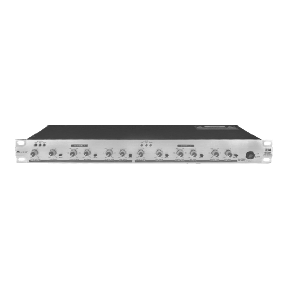
Summary of Contents for Alto X34
- Page 1 User's Manual 3-WAY STEREO/ 4-WAY MONO ACTIVE CROSSOVER www.altoproaudio.com Version 1.0 April 2002 English...
- Page 2 SAFETY RELATED SYMBOLS wire or disconnect the wiring of protective grounding terminal. CAUTION Operating Conditions RISK OF ELECTRIC SHOCK DO NOT OPEN This apparatus shall not be exposed to dripping or splashing and that no objects filled with liquids, This symbol, wherever it appears, alerts you such as vases, shall be placed on this apparatus.
- Page 3 Preface Dear Customer: Thanks for choosing LTO Active Crossover and thanks for choosing the one of results of AUDIO TEAM job and researches. For our LTO AUDIO TEAM, music and sound are more than a job...are first of all passion and let us say... our obsession! We have been designing professional audio products for a long time in cooperation with some of the major brands in the world in the audio field.
-
Page 4: Table Of Contents
4. INSTALLATION & CONNECTION ...................6 4.1 Mains Connection 4.2 Audio Connection 4.3 Rack Mounting 5. APPLICATION .......................7 5.1 X34 3-Way Stereo 5.2 X34 4-Way Mono 6. TECHNICAL SPECIFICATIONS ..................9 7. WARRANTY ........................9... -
Page 5: Introduction
X34 Active Crossover has advanced features such as Clip LED Indicators, CD Horn Equalization, and individual Phase and Mute switches per frequency band. The X34 Active Crossover is an effective and efficient electronic crossover solution, which will give you precise control and superior sound from your loudspeaker system. -
Page 6: Supplementary Descriptions For The Front Panel
INPUT 1 / (INPUT) (4WAY- MONO) CHANNEL 2 CHANNEL 1 33 32 a. Guidable Map for The Rear Panel X34 3-way stereo / 4-way mono active crossover 3-WAY STEREO MODE 4-WAY MONO MODE Fuse Holder AC Inlet Line Input Ch1 Line Input... -
Page 7: Supplementary Descriptions For The Rear Panel
4.1 Mains Connection Please ensure that the LTO X34 Active Crossover is set to the correct supply voltage before plugging the power cord into the wall outlet , use the same fuse as marked on the fuse holder at the AC power connection socket. -
Page 8: Rack Mounting
The most secure mounting is on a universal rack shelf available from various rack manufactures or your music dealer. The X34 Active Crossover fits into one standard 19" rack unit of space. Please allow at least an additional 4" depth for the connectors on the rear panel. Be sure that there is enough air space around the unit for sufficient ventilation and please do not place the X34 Active Crossover on high temperature devices such as power amplifiers etc. -
Page 9: Application
5. APPLICATION 5.1 X34 3-Way Stereo If you want to present your X34 Active Crossover in a 3-way stereo application, please connect the unit in your system as the following illustration step by step: 1. Set Mode switch into stereo Mode. - Page 10 no patch cold required HIGH AMP MID AMP LOW AMP PUSH PUSH 110-120V STEREO MONO AC INPUT 220-240V 95-120V /210-240V 60-50Hz Rated Power Consumption 10W TIDE TIDE HIGH HIGH FUSE: PHASE PHASE BOOST MODE PHASE PHASE BOOST 210-240V: T100mAL 250VAC 95-120V: 200mA 250VAC REPLACE FUSE WITH CORRECT TYPE ONLY...
-
Page 11: Technical Specifications
6. TECHNICAL SPECIFICATIONS Electrical LOW-MID Frequency Range 90Hz-1KHz MID-HIGH Frequency Range 800Hz-10KHz Av=0db, fc=230Hz,2.3KHz HUM & Noise LOW Section (Output@0dB) 98dBu MID S ection utput @0dB) -95dBu -95dBu HIGH Section(Output @0dB) 93dBu S/N Ratio 114dB Controls Input Level continuously variable low, high continuously variable... -
Page 12: Warranty
7. WARRANTY 1. WARRANTY REGISTRATION CARD To obtain Warranty Service, the buyer should first fill out and return the enclosed Warranty Registration Card within 10 days of the Purchase Date. All the information presented in this Warranty Registration Card gives the manufacturer a better under- standing of the sales status, so as to purport a more effective and efficient after-sales warranty service.


Need help?
Do you have a question about the X34 and is the answer not in the manual?
Questions and answers