Table of Contents
Advertisement
Quick Links
Advertisement
Table of Contents

Related Manuals for BaltGaz NEVALUX-5611

Summary of Contents for BaltGaz NEVALUX-5611
- Page 1 User’s and technical staff manual BaltGaz NEVALUX INSTANTANEOUS GAS WATER HEATER FOR DOMESTIC USE BaltGaz NEVALUX-5611 TU 4858-008-26985921-2008 USER’ S MANUAL (TOGETHER WITH THE INSTRUCTIONS ON MOUNTING, TECHNICAL SERVICE AND RE- PAIR OF THE WATER HEATER) 3275-00.000-01 RE...
- Page 2 User’s and technical staff manual Dear customer, Thank you for purchasing our water heater. When purchasing the appliance please check: Scope of delivery and water heater’s resalable condition; Compatibility of pressure and type of gas (NG or LPG) used by you with the type of gas indicated in sections 15 of the following manual and in the table on the appliance’s.
-
Page 3: Table Of Contents
8. CONSTRUCTION AND OPERATION CONTROL OF THE APPLIANCE………………………………………… Ошибка! Закладка не определена. 8.1. Construction of the appliance «BaltGaz NEVALUX-5611» ......... Ошибка! Закладка не определена. 8.2. Operation of the appliance «BaltGaz NEVALUX-5611» ........Ошибка! Закладка не определена. 9. POSSIBLE FAILURES AND METHODS OF THEIR ELIMINATION………………………………………………… 22 10. - Page 4 User’s and technical staff manual 13.12. Replacement of micro switch (water flow sensor) ........... Ошибка! Закладка не определена. 13.13. Battery section replacement ................Ошибка! Закладка не определена. 13.14. Replacement of the water and gas unit’s electromagnetic valve ....Ошибка! Закладка не определена. 13.15.
-
Page 5: Safety Measures Indication
User’s and technical staff manual 1. SAFETY MEASURES INDICATION 1.1. In order to avoid accidents and the appliance’s breakdown it is prohibited to: Install or put the appliance into operation by yourself; Switch the appliance on and regulate it without being acquainted with the present user’s manual; ... -
Page 6: Description And Operation Of The Appliance
Appliance’s purpose 2.1. 2.1.1. Instantaneous domestic gas water heater « BaltGaz NEVALUX-5611» hereinafter referred to as “Appliance” is manufac- tured according to TU 4858-008-26985921-2008 (GOST Р 51847-2009) standard and designed for water heating for sanitary purpos- es (washing the dishes, laundry, bathing) in the apartments and individual residential premises. -
Page 7: Supply Package
– when using alkaline power elements with high energy output ratio. 2.3. Supply package The supply package is presented in the Table 2. Table 2 Designation Name Quantity, pcs. Water heater «BaltGaz NEVALUX-5611» 3275-00.000 User’s manual 3275-00.000-01 RE 3275-10.000-01 package 3208-06.600 Mounting hardware set Spare parts 3103-00.014... -
Page 8: Usage Of The Appliance
User’s and technical staff manual 3. USAGE OF THE APPLIANCE For normal and safe appliance operation the fulfillment of conditions presented in p. 2.2.9, 2.2.11 and 2.2.14 (Table 1) must be provided. Non- compliance with these conditions can cause the appliance’s inappropriate or unstable operation or its breakdown. -
Page 9: Switching The Appliance Off
User’s and technical staff manual Note 2. Water heating temperature is limited by the appliance’s heating effect: when water consumption is high, especially in winter time, water at the appliance’s outlet might have insufficient temperature even at maximal gas consumption. In this case in or- der to increase water temperature it is necessary to reduce water flow going through the appliance. -
Page 10: Appliance Treatment
User’s and technical staff manual 4. APPLIANCE TREATMENT To ensure long-term and failure-free-free operation of the appliance and keep its operating characteristics it is necessary to regu- larly effectuate its examination, treatment and technical service. To ensure fire safety it is necessary to carefully and attentively look after the burners’ cleanliness, not to allow smoky flame ap- pearance at gas combustion, which leads to soot deposit appearance on the heat exchanger. -
Page 11: Place And Scheme Of Installation
User’s and technical staff manual After the appliance’s installation, checking its working capacity and the alliance’s owner’s instructing by an employee of the or- ganization that installed the appliance, a mark about the appliance’s installation should be made in the Certificate of installation, tech- nical service and repair and in the warranty coupons ATTENTION! Before installing the appliance it is necessary to check the compliance of the settings indicated in the Ac- ceptance certificate and in the table on the appliance with the type and pressure of gas available at the place of the appliance’s... -
Page 12: Mounting The Appliance
User’s and technical staff manual Scheme9. Scheme of appliance’s installation 7.2. Mounting the appliance 7.2.1. Before installing the appliance it is recommended to removing the casing, for this it is necessary to do the following: a) Remove the knobs 1 and 2 (see Scheme 1,2) by pulling them towards yourself b) Unscrew the panel fixation screw;... -
Page 13: Connecting The Appliance To The Gas System
User’s and technical staff manual 7.4. Connecting the appliance to the gas system In order to ensure stable operation of the appliance it is necessary to effectuate the gas line connection 7.4.1. with metal pipes or flexible hose with an internal diameter not less than 13 mm. The flexible hose for supplying gas, in accordance with the SP 62.13330.2011 requirements must be resistant to the supplied gas at given tem- perature and pressure. -
Page 14: Connecting The Appliance To The Exhaust Flue
User’s and technical staff manual Table 4. Flexible hoses installation scheme Wrong Correct Table 4 Flexible hoses installation scheme Connecting the appliance to the exhaust flue 7.7.1. In order to remove all combustion products and to ensure safe operation of the appliance the following requirements to the exhaust flue and flue pipe, connecting the exhaust flue with the appliance should be fulfilled: - the exhaust flue should be air-tight and resistant to the heating load and impact of combustion products It is not allowed to use ventilation channels to remove the combustion products;... -
Page 15: Installation Of The Appliance's Power Elements
User’s and technical staff manual 1 – flue pipe; 3 – heat-resistant sealant; 2 – gas removal device hose; 4 – aluminum heat-resistant tape Scheme 7. Scheme of flue pipe connection 7.7.2. Variant of connecting appliance to the exhaust flue is represented on the scheme 11. correct wrong The end of the flue pipe is too close to the... -
Page 16: Rendering The Appliance To Another Type And Pressure Of Gas
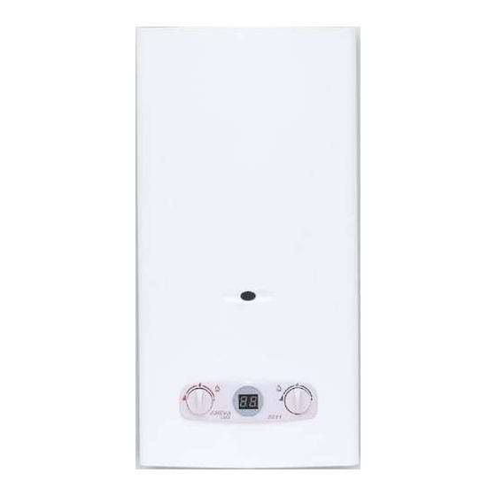
8.1. Construction of the appliance “BaltGaz NEVALUX 5611” 8.1.1. Wall-mounted appliance « BaltGaz NEVALUX-5611» (scheme 2) has a rectangular form with a detachable casing 4. On the casing’s front surface there are: water consumption regulation knob 1, gas consumption regulating knob 2, wa- ter temperature display 3 and a viewing window 5 for observing the burner flame. - Page 17 User’s and technical staff manual 1 – water consumption regulator; 12 – heat exchanger; 2 – gas consumption regulator; 13 – electromagnetic valve;...
- Page 18 User’s and technical staff manual 3 – table; 14 – battery section 4 – gas and water unit; 15 – electronic control block; 5 – burner; 16 – thermo relay(draught sensor); 6 – cold water supply fitting; 17 – micro switch (water flow sensor); 7 –...
-
Page 19: Possible Failures And Methods Of Their Elimination
User’s and technical staff manual 9. POSSIBLE FAILURES AND METHODS OF THEIR ELIMINATION Table 6. Possible failures of the appliance “BaltGaz NEVALUX 5611” Failure Probable reason Methods of elimination The appliance does not switch on Power elements are not installed (or wrong in-... -
Page 20: General Instructions
User’s and technical staff manual The lame of the main burner is Dust deposit on the burner’s nozzles and inner Effectuate the burner’s cleaning.* weak, stretched, with yellow smoky surfaces tongues. After a short period of operation Insufficient draught (the appliance is switched Close the hot water tap and at the next switch- the appliance switches off. -
Page 21: Examination
User’s and technical staff manual In order to ensure fire safety it is necessary to carefully monitor cleanliness of the burners, not allow smoky flame during gas combustion, which causes soot deposit on the heat exchanger. At the same time the gaps between the heat exchanger’s fins are cov- ered with soot, and consequently the flame casts out of the combustion chamber, what may lead to fire. - Page 22 c) Fill in the heat exchanger’s pipeline with the prepared solution and leave it there for 10-15 minutes, then drain the solution and wash the pipeline thoroughly with water; d) Repeat all the process if necessary. 12.3.3. Sealings replacement During technical service when disassembling or assembly of water or gas pipelines is effectuated, it is necessary to obligatory install new sealings.
-
Page 23: Works Order At The Appliance's Repair And Components Replacement
13. WORKS ORDER AT THE APPLIANCE’S REPAIR AND COMPONENTS REPLACEMENT CAUTION! Operations for the appliance’s repair, connected with disassembly of its gas and water pipelines, must necessarily be performed after the appliance’s complete switching off (taps must be closed on the appliance’s water and gas inlet lines). -
Page 24: Replacement Of The Pipe Ofhot Water Outlet From The Heat Exchanger
13.6.5. Check the appliance’s operation. Water leakage is unacceptable. 13.7. Replacement of the pipe of hot water outlet from the heat exchanger. 13.7.1. Remove the casing, see p. 13.1. 13.7.2. Disconnect the cables and remove the thermo relay 22, unscrewing the loop screws 25. 13.7.3. - Page 25 Manual for technical staff ANNEX I. scheme of the appliance with separated components Scheme 18 View of the appliance with separated parts...
- Page 26 Manual for technical staff Scheme 19. Components of the water and gas unit 3275-02.200 Scheme 20. Components of the water unit STG-W4P1...
- Page 27 Table 8. Catalogue of the components of the appliance “BaltGaz NEVALUX-5611” Pos. Name Designation Body frame 3272-01.000 Heat exchanger* 3272-07.000 Burner* (10 blades) family, group Н). 1.3 kPa NG (G20. 2 3272-02.100 family, group Н). 2.0 kPa NG (G20. 2 3272-02.100-02...
Need help?
Do you have a question about the NEVALUX-5611 and is the answer not in the manual?
Questions and answers