Advertisement
Quick Links
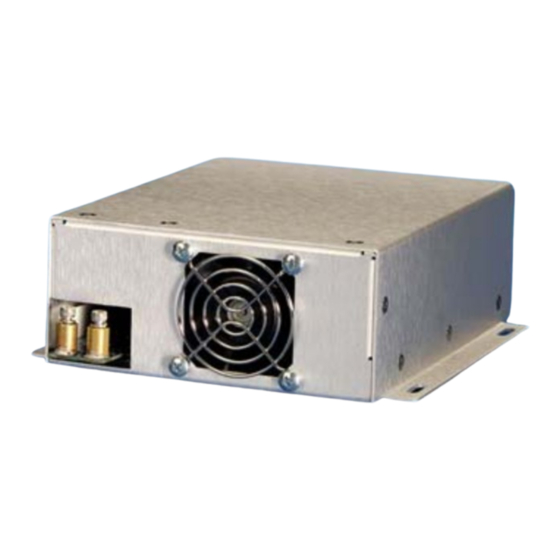
USER MANUAL
LDD-100/150/250-XX-YY
CW Diode Driver Power Supplies
The LDD-100/150/250 family of high power CW diode laser can be configured for
output currents from as low as 10A to output current up to 80A at maximum
power levels from 100W to 250W.
As a laser diode driver, the LDD diode driver acts as a programmable current
source and delivers constant current based on the input program signal,
Iprogram(+), which is normally 0-10V. All units are configured with a maximum
current and maximum voltage capability, depending on the user's requirements.
LDD power supplies will deliver current, as programmed, into any load, providing
the voltage requirements of that load do not exceed the maximum rated voltage
of the unit. When the required compliance voltage is higher then the maximum
rated output voltage of the unit, the unit will limit output current.
LDD diode drivers utilize a proprietary low loss, high frequency power factor
correction circuit which keeps power factor above 0.98. Power factor corrected
power supplies use up to 30% less input current and meet stringent IEC
harmonic requirements. The output inverter is a state-of-the-art zero voltage
switching (ZVS) inverter which permits very high frequency power conversion
with minimum losses and electromagnetic noise.
02001026
Operation Manual:
Page 1 of 13
Rev 1 ECO 7062
LDD-100/150/250-XX-YY
Advertisement

Related Manuals for Lumina Power LDD-100


Summary of Contents for Lumina Power LDD-100
- Page 1 LDD-100/150/250-XX-YY CW Diode Driver Power Supplies The LDD-100/150/250 family of high power CW diode laser can be configured for output currents from as low as 10A to output current up to 80A at maximum power levels from 100W to 250W.
-
Page 2: Table Of Contents
LDD-100/150/250 Specifications LDD-100/150/250 Interface INSTALLATION AND OPERATION Optional RS-232 Protocol Tables and Figures LDD Laser Diode Power Supply Block Diagram LDD-100/150/250 Outline Drawing LDD-100/150/250 Interface Table LDD-100/150/250 Interface Schematic Input Connections Output Connections Response of output to Enable Signal AC Input Requirements... -
Page 3: Ldd Diode Drivers - Theory Of Operation
AC Input Power Circuitry AC input power is processed through a line filter to reduce the conducted EMI to an acceptable level. The LDD-100/150/250 line filter has minimum capacitance to ground to minimize leakage currents. Earth Ground stud is provided near the AC input terminals and should be connected to the system ground. - Page 4 All internal power supply requirements as well as the external +/-15V and +5V power supplies are derived from the power factor control boost inductor. All auxiliary power supplies are regulated by standard linear regulators Figure 1 LDD-100/150/250 Block Diagram 02001026 Operation Manual: Page 4 of 13 Rev 1 ECO 7062...
-
Page 5: Ldd-100/150/250 Specifications
Forced air Regulatory Leakage Current: <350uA Approvals: Medical Safety: LDD-100/150-XX-YY: UL60601-1, UL60950-1:2001, IEC 60601-1, EN 60601- 1, CAN/CSA C22.2 No. 601.1-M90 LDD-250-XX-YY: IEC60950-1:2001 (1 Edition), EN 60950-1,2001, UL60950-1, CSA22.2 No. 60950-03 Emissions/Immunity: FCC 47 CFR Class A Emissions, EN55011:1998 Group 1 Class A Emissions,... - Page 6 Figure 2 LDD-100/150/250 Outline Drawing 02001026 Operation Manual: Page 6 of 13 Rev 1 ECO 7062 LDD-100/150/250-XX-YY...
- Page 7 (output) Up to 0.5A output current available. Referred to (-) output of the power supply. TABLE 1: LDD-100/150/250 Interface * If maximum compliance voltage is less than 10V, Vout Monitor will read output voltage directly. If maximum compliance voltage is greater than 10V, then...
-
Page 8: Ldd-100/150/250 Interface
Figure 3 LDD-100/150/250 Interface 02001026 Operation Manual: Page 8 of 13 Rev 1 ECO 7062 LDD-100/150/250-XX-YY... -
Page 9: Installation And Operation
Figure 4. (Although the user interface is typically designed by the user, Lumina Power can provide any assistance necessary to modify interface program and monitor levels) See Table 1 and Figure 3 for description of LDD-100/150/250 Interface and the associated simplified interface schematic. - Page 10 • Ground wire shall be crimped to a # 8 ring-lug and connected to the ground stud. IMPORTANT APPLICATON NOTE REGARDING AC INPUT POWER AC Input wires should be at least #16 AWG, rated for at least 300V and 105DegC. 02001026 Operation Manual: Page 10 of 13 Rev 1 ECO 7062 LDD-100/150/250-XX-YY...
- Page 11 IMPORTANT SYSTEM NOTE ON AC INPUT POWER LDD-100/150/250 units are fused on both input lines. It does not matter which of the two AC inputs are designated Line or Neutral. AC input power requirements for LDD-100/150/250 models are as follows:...
- Page 12 Optional RS-232 Protocol LDD-100/150/250-XX-YY-RS Refer to Figure 2, LDD-100/150/250 Outline Drawing for location of RS-232 Connector The RS232 interface for Lumina supplies has the following characteristics: Baud rate: 9600 Command format: ASCII characters terminated by carriage return Reply formats: ASCII characters terminated by carriage return Connection: 9 Pin “D”...
- Page 13 Must be used with RS Interface Servicing LDD-100/150/250 Diode Drivers LDD-100/150/250 units have no serviceable parts. Do not attempt to repair or service this unit in the field. For further information, contact Lumina Power at 978-241-8260. Lumina Power, Inc.
Need help?
Do you have a question about the LDD-100 and is the answer not in the manual?
Questions and answers