Table of Contents
Advertisement
Quick Links
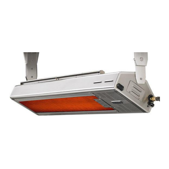
LYNX EAVE MOUNT PATIO HEATER
LHEM48
CARE AND USE MANUAL
Installation of Lynx Eave Mounted Patio Heater should only be installed by a person knowledgeable about gas appliances
TO THE INSTALLER: Please read these instructions completely before installation. Give this manual to the owner.
TO THE OWNER: Keep this manual in a safe place for future reference.
NOTE: Remote control devices have been pre-initialized and are ready to use.
Lynx Professional Grills, 5895 Rickenbacker, Commerce, CA 90040 PH (888) 289-5969
P/N 33535 10/2013
Advertisement
Table of Contents

Related Manuals for Lynx LHEM48


Summary of Contents for Lynx LHEM48
- Page 1 LHEM48 CARE AND USE MANUAL Installation of Lynx Eave Mounted Patio Heater should only be installed by a person knowledgeable about gas appliances TO THE INSTALLER: Please read these instructions completely before installation. Give this manual to the owner. TO THE OWNER: Keep this manual in a safe place for future reference.
- Page 2 WARNING READ THIS MANUAL CAREFULLY and completely before using your heater to reduce the risk of: 1. Fire 2. Burn hazard, personal injury or property damage 3. Unapproved installation or servicing. THIS PRODUCT IS DESIGNED FOR OUTDOOR USE ONLY. Improper installation, adjustment, alteration, service or maintenance can cause property damage, injury or death.
- Page 3 THIS MANUAL MUST REMAIN WITH THE PRODUCT OWNER FOR FUTURE REFERENCE. This product complies with ANSI standard Z83.26-2007/ Z83.26a-2008 and CSA 2.37-2007/ CSA 2.37a-2008 and has been tested and approved by Intertek. To obtain replacement parts or service contact: Lynx Professional Grills, 5895 Rickenbacker, Commerce, CA 90040 888-289-5969...
- Page 4 WARNING 1. This gas appliance and its individual shutoff valve must be disconnected from the gas supply piping system during any pressure testing of that system at test pressures in excess of 1/2 psi (3.5 kPa). This gas appliance must be isolated from the gas supply piping system by closing its individual manual shutoff valve during any pressure testing of the gas supply piping system at test pressures equal to or less than 1/2 psi (3.5 kPa).
-
Page 5: Table Of Contents
TABLE OF CONTENTS- Lynx Eave Mount Patio Heater Important Safety Precautions…………………………………………………….….….i-iii Lynx Eave Mount Patio Heater-Important Features……………………….…….1 Mounting Considerations………………………………………………………………...1-2 Code Requirements…………………………………………………………………………..2 Gas Supply and Connections……………………………………………………..…….2-3 Electrical Supply Specifications and Connections…………………………………3 Mounting the Heater………………………………………………………………..…..…4-8 Making the Gas Connections……………………………………………………….…..8-9 Checking for Gas Leaks…………………………………………………………………..….10 Making the Electrical Connections…………………………………………………..11... -
Page 6: Lynx Eave Mount Patio Heater-Important Features
P a g e Thank you for your purchase of our LYNX Deluxe Eave Mount Patio Heater. This product has been manufactured with the highest quality materials available, and combines the most advanced, state of the art, internal components with cutting edge, heater design technology . -
Page 7: Code Requirements
GAS SUPPLY AND CONNECTIONS Each Lynx Eave Mount Patio Heater is built specifically to be run either with NG (Natural Gas) or LP (Liquid Propane). This heater is dedicated to one of these two gas types and it is not easily field convertible. Identify the type of gas that you will be using, and identify the heater gas type. -
Page 8: Electrical Supply Specifications And Connections
This drop in pressure can affect overall heater performance. IMPORTANT NOTE: There is a pressure tap built into the valve system used on the Lynx Eave Mount Patio Heater. To access this tap, remove the 2 screws which hold the louvered plate on the END CAP of the heater. -
Page 9: Mounting The Heater
Initial mounting considerations have been discussed, and now it’s time commit your placement theory into motion. Consider the following pieces of information to help you through: The Lynx Eave Mount Patio Heater is made from the finest materials available- heavy gauge stainless steel. As a result, this heater is heavy- It weighs around 50 pounds and must be mounted securely. - Page 10 P a g e If it has been determined that the heater be mounted straight down, i.e., with no angle on its pivot point, then the heater should be mounted NO CLOSER than 14” from the ceiling. The side clearances should be NO CLOSER than 12” to a side wall, and the rear clearances should be NO CLOSER than 12”...
- Page 11 P a g e IMPORTANT NOTE: Use only the mounting brackets provided with this heater. Heater must be installed in a horizontal manner parallel with the ground. The heater can, however, be tilted upward to a maximum of 30 degrees. NEVER mount the heater on a vertical axis.
- Page 12 P a g e Mounting Bracket Assembly Locate and assemble the mounting brackets based on your pre-determined mounting distance to the ceiling (14” if mounting flat, 18” if mounting at an angle). Slide the long bracket extension INSIDE the main mounting bracket until the intended set of holes align.
-
Page 13: Making The Gas Connections
P a g e After assembling the mounting brackets, they can now be installed in the pre-selected location. Please again refer to the mounting bracket spacing diagram, page 4. The spacing of the outer-most sets of holes of the mounting brackets is 48”. - Page 14 This typical flexible line would be ½” I.D. (5/8” O.D.) stainless steel, with ½” MIP (male) fittings at both ends. (Lynx P/N 31546). A ½” FIP (female) coupling would then be used to connect the flex line to the hard pipe. Please note, for Natural Gas (NG) installations, a regulator is not required, as the heater is equipped with a built-in regulator inside the valve.
-
Page 15: Checking For Gas Leaks
For Liquid Propane (LP) , open the gas cyinder knob by a minimum of 1 full turn and if connected to the Lynx LQD-EM, turn the in-line valve ¼ turn so that the lever is parallel and in- line with the hose. -
Page 16: Making The Electrical Connections
P a g e | 11 MAKING THE ELECTRICAL CONNECTIONS If the AC adaptor is NOT being used, and it is intended to run the heater from battery power only, then NO special electrical connections need to be considered. Assure the the AC/DC output plug, at the right end of the heater, is covered with the rubber plug that is mounted under the jack. - Page 17 P a g e | 12 Touch Screen Remote Transmitter-remove the cover on the back of the remote control unit and install (4) AAA 1.5 V batteries. Take special note of the (+) and (-) terminals. Heater- remove the (2) screws holding the louvered end plate at the far, right end of the heater. This is the SMALLER of the 2 access plates.
-
Page 18: Initializing The Remote Control System
P a g e | 13 INITIALIZING THE REMOTE CONTROL SYSTEM- REFERENCE ONLY Locate the wireless wall switch, and press the “OFF” button. Confirm that the red LED flashes. The LED will flash every time that any of the 4 buttons is pushed. This confirms that the unit is functioning, and that the button selection has been confirmed. -
Page 19: Basic Operation Of Your Heater
If this is a Liquid Propane (LP) installation, open the gas cylinder valve by a minimum of one full turn, and if connected to the Lynx LQD-EM, turn the in-line valve lever by ¼ turn so that the lever is parallel and in-line with the gas line. -
Page 20: Touch Screen Remote Control Operation
P a g e | 15 then ‘time out’. This is part of the safety system. If this occurs, simply turn the wall switch to OFF, and then turn back to ON. The spark will return to its normal function. Repeat this operation until the pilot lights. Once the pilot lights, the heater will light within seconds. - Page 21 P a g e | 16 TOUCH SCREEN REMOTE CONTROL LAYOUT MODE Zone AIR TEMP Zone SET TEMP Zone TIME/PROG Zone LIGHT Zone (Unused) FLAME Zone llleftleft ((A AUX Zone (Unused) FAN Zone (Unused) DOWN Button MODE/SET Button UP Button MODE/SET Heater Modes of Operation Operation modes:...
- Page 22 P a g e | 17 MANUAL OFF Mode: Transmits heater OFF command. LCD Displays: o MODE Zone: OFF is displayed o ROOM /AIR TEMP Zone: Measured temperature is displayed o SET TEMP Zone: Blank o TIME/PROG Zone: Current day indicator and current time is displayed o FLAME Zone: Blank MANUAL ON Mode: ...
- Page 23 P a g e | 18 TIME/PROG Zone: Blank FLAME Zone: Blank THERMOSTAT OFF LCD Displays: o MODE Zone: THERMO and OFF is displayed ROOM /AIR TEMP Zone: Measured temperature is displayed o SET TEMP Zone: SET TEMP is displayed o Time of day is displayed Air Temperature Limit Function: When using the heater with the remote control transmitter, always keep the remote transmitter by your side, i.e., at the...
- Page 24 P a g e | 19 o ROOM/AIR TEMP Zone: Measured temperature is displayed o SET TEMP Zone: Blank o TIME/PROG Zone: Current day indicator, current time, and Program status (P1-OFF or P2-OFF) is displayed o FLAME Zone: Blank Program ON LCD Displays: o MODE Zone: THERMO and either ON or OFF is displayed o ROOM/AIR TEMP Zone: Measured temperature is displayed...
- Page 25 P a g e | 20 M T W T F & & on LCD will flash, then you can use UP or DOWN to change the setting of “P2 ON". Then, use SET button to enter into next setting. M T W T F &...
-
Page 26: Low Battery Indicator/ Replacing The Batteries
P a g e | 21 Continuous Pilot Feature: In some cases, or in some locations where severely cold weather persists, it may be an advantage for you to set your heater so the small pilot flame stays continuously ON. This keeps the pilot area warm and allows immediate start-up of your heater. -
Page 27: Pilot Flame Adjustment
P a g e | 22 Replacing Batteries in the Heater- Remove the (2) screws holding the louvered end plate at the far, right end of the heater. This is the SMALLER of the 2 access plates. The battery pack will be mounted directly inside, and onto the endplate. Carefully lift the (black) sealed pack out from the retaining clip. -
Page 28: Trouble Shooting
TROUBLESHOOTING GUIDE Page 23 LYNX EAVE MOUNTED PATIO HEATER CORRECTION-WHAT TO DO PROBLEM Pilot Igniter does not spark Press the 'ON' button on the wireless wall switch. Verify that the LED flashes RED as the button is pushed. If you can now hear a spark coming from the pilot, then the problem may be the touch screen remote control. - Page 29 Page 24 TROUBLESHOOTING GUIDE LYNX EAVE MOUNTED PATIO HEATER CORRECTION-WHAT TO DO PROBLEM Remote control shows air Remote control batteries are low. Check for the 'Low Battery" icon in temperature readout, but will the readout of the remote control. Replace batteries in remote using (4)AAA.
-
Page 32: Warranty Information
This warranty applies to commercial applications such as apprtment buildings, restaraunts, golf clubs and food service loccations. Lynx will replace or repair parts found to be defective at no cost to the original purchaser within 90 days of the original date of purchase.
Need help?
Do you have a question about the LHEM48 and is the answer not in the manual?
Questions and answers