Sea Tel DAC-2202 Installation And Operation Manual
Antenna control unit
Hide thumbs
Also See for DAC-2202:
- Installation and operation manual (89 pages) ,
- User manual (16 pages) ,
- Operator's manual (22 pages)
Table of Contents
Advertisement
Quick Links
Sea Tel, Inc.
4030 Nelson Avenue
Concord, CA 94520
Tel: (925) 798-7979
Fax: (925) 798-7986
Email: seatel@cobham.com
Web: :
www.cobham.com\seatel
August 26, 2010
INSTALLATION AND OPERATION MANUAL
DAC-2202 ANTENNA CONTROL UNIT
Sea Tel Inc doing business as Cobham SATCOM
FOR SEA TEL MODEL
Sea Tel Europe
Unit 1, Orion Industrial Centre
Wide Lane, Swaythling
Southampton, UK S0 18 2HJ
Tel: 44 (0)23 80 671155
Fax: 44 (0)23 80 671166
Email: seatel@cobham.com
Web:
Document. No. 126523 Revision G2
www.cobham.com\seatel
Advertisement
Table of Contents

Related Manuals for Sea Tel DAC-2202


Summary of Contents for Sea Tel DAC-2202
- Page 1 Southampton, UK S0 18 2HJ Fax: (925) 798-7986 Tel: 44 (0)23 80 671155 Email: seatel@cobham.com Fax: 44 (0)23 80 671166 Web: : www.cobham.com\seatel Email: seatel@cobham.com Web: www.cobham.com\seatel Sea Tel Inc doing business as Cobham SATCOM August 26, 2010 Document. No. 126523 Revision G2...
- Page 2 All Rights Reserved. The information contained in this document is proprietary to Sea Tel, Inc.. This document may not be reproduced or distributed in any form without the consent of Sea Tel, Inc. The information in this document is subject to change without notice.
-
Page 3: Table Of Contents
DAC-2202 Antenna Control Unit Table of Contents INTRODUCTION ......................................1-1 1.1................................1-1 ENERAL ESCRIPTION OF YSTEM 1.2................................1-1 ENERAL COPE OF ANUAL 1.3................................1-1 UICK VERVIEW OF ONTENTS ... - Page 4 Table of Contents DAC-2202 Antenna Control Unit 4.10..............................4-5 ONITOR ONTROL ONNECTIONS 4.11. BDE E ................................4-5 NSTALL THER QUIPMENT 4.12........................................4-5 INAL HECKS 4.12.1. Visual/Electrical inspection ..............................4-5 ...
- Page 5 DAC-2202 Antenna Control Unit Table of Contents DIAGNOSTIC M&C SOFTWARE INSTALLATION & USE ....................7-1 7.1. M&C S ............................. 7-1 IAGNOSTIC OFTWARE 7.2..............................7-1 OFTWARE NSTALLATION 7.3. : TCP/IP B ..........................
- Page 6 Table of Contents DAC-2202 Antenna Control Unit 8.3.2. 1:1 SYNCHRO ....................................8-2 8.3.3. 360:1 Synchro ..................................... 8-2 8.4............................8-3 ISPLAY FFSETS PTIMIZING ARGETING 8.5............................. 8-3 EDESTAL ONTROL ONFIGURATION ...
-
Page 7: Introduction
Television Receive Only (TVRO) Systems are comprised of two major sections: The Above-Decks Equipment (ADE) is comprised of the Sea Tel antenna & radome assembly which is mounted outside, on an upper deck location chosen for best satellite reception. The Below-Decks Equipment (BDE) includes the Antenna Control Unit and will have satellite receiver(s), TV set(s) and all other ancillary equipment that is mounted in various locations throughout the interior of the ship. - Page 8 Introduction DAC-2202 Antenna Control Unit THIS PAGE INTENTIONALLY LEFT BLANK...
-
Page 9: Operation
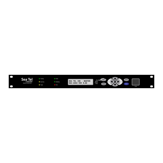
Operation When power is turned ON, the ACU Display will initially show “SEA TEL INC - MASTER” and the ACU software version (ie DAC-2202 VER 6.xx ). 10 seconds later, the display will switch to “SEA TEL INC - REMOTE” and “INITIALIZING” for approximately two minutes while the Pedestal Control Unit (PCU) completes initialization of the antenna pedestal and then reports its Model &... -
Page 10: Basic Function Of Front Panel Keys
Operation DAC-2202 Antenna Control Unit 2.3. Basic Function of Front Panel Keys Keyboard operation is very simple and straightforward. Basic function of each key is: Press NEXT to cycle through the four main menus; Ship, Satellite, Antenna and Status (refer to the Operation Flowcharts). -
Page 11: Display & Entry Operation Menus
DAC-2202 Antenna Control Unit Operation Initializing - (Green LED) ON indicates that the Antenna is initializing. Initialization of the antenna will take approximately two minutes. Error - (Red LED) ON indicates that one, or more, discrete system errors have occurred. Refer to Status – Error Code information menu to determine which error(s) have occurred. - Page 12 DVB/SCPC V3 SCPC VER 5.XX DVB VER 4.XX NBIF VER 4.XX DVB VER 5.XX No RCVR Found SEA TEL INC – IO MOD COMMIF VER 1.12 This is the model configuration Status and software version of the PCU. Ship Menu...
-
Page 13: Ship Information Menus
DAC-2202 Antenna Control Unit Operation 2.6.1. Ship Information Menus. Display Meaning LAT 38 N LON 122 W Press the NEXT key until the Ship menu is displayed. This is the display of the HDG 000.0 000.0 current Ship information. LAT 38.0 N Press ENTER to access the Latitude sub-menu. -
Page 14: Satellite Information Menus
Operation DAC-2202 Antenna Control Unit 2.6.2. Satellite Information Menus. Display Meaning SAT 101 W THRS 1234 Press the NEXT key until the main Satellite menu is displayed. This is the display of FREQ 1100 1234 the current Satellite tracking information. - Page 15 DAC-2202 Antenna Control Unit Operation Press DOWN or ENTER to access the Sat ID Receiver Frequency entry mode. In DVB Mode The individual settings of the Satellite Identification tracking receiver and the current signal level (AGC) will be displayed in each of the sub-menus below. To enable SCPC...
- Page 16 Operation DAC-2202 Antenna Control Unit Press DOWN or ENTER to access the Volt sub-menu. This setting is used to select Volt HORZ AGC 1234 the Voltage output from the tracking receiver, based on the desired received transponder polarity. Available selections are; HORZ (18VDC), LHCP (18VDC), VERT (13VDC) or RHCP (13VDC).
-
Page 17: Antenna Information Menus
DAC-2202 Antenna Control Unit Operation Press DOWN or ENTER to access the NID sub-menu. This setting, a four digit 0000 AGC 1234 HEX value with a valid range of 0000-FFFF, is based on the desired received transponders’ Network ID (NID). If this parameter is provided in decimal format, it will have to be converted to hexadecimal for entry. -
Page 18: Status Information Menus
Operation DAC-2202 Antenna Control Unit EL 056.7 Press DOWN or ENTER to access the Elevation sub-menu. This allows you to AGC 1234 target the antenna to a desired Elevation position. Range of input is 00.0-90.0. To target a new elevation position, press the LEFT or RIGHT arrow key to bring the cursor up under the character to the left, or right, of the decimal point respectively. - Page 19 DAC-2202 Antenna Control Unit Operation CONTROL Press the ENTER key once to display the Status – Control Tracking sub-menu. TRACKING This is the display of the current Tracking and Band Selection information. To turn the Tracking status On or Off, press the Track key, or press the RIGHT arrow to bring up a cursor under the current tracking condition and then Press the UP arrow to toggle status ON/OFF.
-
Page 20: Setup Parameter Display And Entry Menus
Both DishScan Phase timing mark and Amplitude drive are adjustable by the N7xxxx Remote Command parameter. For more information on this parameters refer to Sea Tel document 123400. While viewing the AZIMUTH or ELEVATION sub-menu, the DishScan drive commands issued (2, 4, 6 or 8) will be visible in the lower left corner of the display. -
Page 21: Searching Operation
DAC-2202 Antenna Control Unit Operation When Tracking is turned OFF these commands indicate drive that is required, but will not be sent to the antenna to be carried out. If the antenna is already perfectly pointed, the signal received (AGC) throughout each of the 4 quadrants will be equal and no tracking decision is made. -
Page 22: Inclined Orbit Search Pattern
Operation DAC-2202 Antenna Control Unit The antenna will then search up in azimuth one Search Increment, search up one Search Increment in elevation, search down two Search Increments in azimuth, search down two Search Increments in elevation, etc until Search Limit is reached. When the end of the search pattern is reached, the ACU will retarget the antenna to the start point shown in the graphic below. -
Page 23: No Gyro Search Pattern
DAC-2202 Antenna Control Unit Operation search up along the polarization angle SWEEP INCR degrees, step two Search Increments to the left, search down, etc expanding out in the search pattern until Search Limit is reached. When the end of the search pattern is reached, the ACU will retarget the antenna to the calculated Azimuth and Elevation point. -
Page 24: Auto-Polarization Operation
Operation DAC-2202 Antenna Control Unit 2.2. Auto-Polarization Operation Another feature of the ACU is auto-polarization. The ACU automatically calculates the required polarization angle for the feed every 2 seconds based on ship's Latitude, Longitude and the Satellite Longitude. If the polarization of the feed is not properly peaked, the ACU will send a command to the PCU to drive the 24V DC motor drive on the feed to peak the polarization. -
Page 25: Basic Configuration Information
(proper option files) and the ACU/PCU (setup parameters) are actually compatible for the intended satellite(s). 3.1.2. Interface requirements: 3.1.2.1. Hardware Sea Tel Antenna Control Units Model DAC2202 or DAC2302. Any Satellite modem manufacturer that is compatible with OpenAMIP CAT5 Patch cable 3.1.2.2. Software Sea Tel model DAC2202: ACU software version 6.06 or greater... -
Page 26: Components Of The System Configuration
Television Receive Only (TVRO) Systems are comprised of two major sections: The Above-Decks Equipment (ADE) is comprised of the Sea Tel antenna & radome assembly which is mounted outside, on an upper deck location chosen for best satellite reception. The Below-Decks Equipment (BDE) comprises of an Antenna Control Unit and will have satellite receiver(s), TV set(s) and all other ancillary equipment that is mounted in various locations throughout the interior of the ship. -
Page 27: Installation
Assure that the Gyro Compass output is turned OFF when handling and connecting wiring to the Terminal Mounting Strip. CAUTION - Allow only an authorized dealer to install or service the your Sea Tel System components. Unauthorized installation or service can be dangerous and may invalidate the warranty. -
Page 28: Install The Terminal Mounting Strip (Tms)
ACU. Connect the 9 pin ribbon cable (or NMEA serial cable) from the Terminal Mounting Strip to J2 “NMEA” DB9 on the rear panel of the ACU. Figure 4-1 Rear Panel DAC-2202 ACU 4.6. Install the Base Multiplexer Panel If your antenna system includes a base multiplexer panel, install the panel in the rear of the standard 19”... - Page 29 AGC & GND - External AGC, or Modem Lock, input. External AGC input to the DAC-2202 must be 0 to 15 Volts DC analog signal, positive going voltage proportional to satellite signal input level and must be real-time in its response to antenna pointing.
-
Page 30: Ac Power To The Acu
Installation DAC-2202 Antenna Control Unit within 0.2 degrees of peak pointing to the satellite for a minimum of 5 seconds (FCC part 25.221 & 25.222 TX Mute requirement). 4.7.1.4. TS2 Synchro Gyro Compass Input. Use the R1, R2, S1,S2 and S3 screw terminals to connect the Synchro Gyro Compass to the ACU. -
Page 31: Monitor And Control Connections
J3 M&C - The Monitor and Control port allows external control from a PC using a communications program such as Sea Tel ProgTerm or DacRemP via a straight 9 wire serial cable. This Port is used in conjunction with a diagnostic software connection to configure all communications settings, and/or for an Authorized Sea Tel Dealer to perform software uploads to the PCU, ACU Main PCB, and DVB Receiver. - Page 32 Installation DAC-2202 Antenna Control Unit THIS PAGE INTENTIONALLY LEFT BLANK...
-
Page 33: Operator Settings
DAC-2202 Antenna Control Unit Setup Setup Below are basic steps to guide you in setting up the ACU. Assure that the Antenna Pedestal (ADE) has been properly installed. If your system includes the OPTIONAL Touch Screen Controller, refer to the Operation & Setup chapters in the TSC-10 manual to setup the ACU. - Page 34 GYRO TYPE 0002 being used for Heading input to the system. Execute EXIT EXIT EXIT SETUP This parameter should be set to 72 for automatic polarization control. Execute POLANG TYPE 0072 EXIT Distributed By: _________________________________________________ Authorized Sea Tel Dealer Phone: ______________________________...
-
Page 35: Auto Trim
DAC-2202 Antenna Control Unit Setup 5.5. AUTO TRIM The Auto Trim function will automatically calculate and set the required Azimuth and Elevation trim offset parameters required to properly calibrate the antennas display to the mechanical angle of the antenna itself, while peaked ON satellite. -
Page 36: Az Trim
Setup DAC-2202 Antenna Control Unit Continue with Azimuth trim, then re-target the satellite several times to verify that targeting is now driving the antenna to a position that is within +/- 1.0 degrees of where the satellite signal is located. -
Page 37: Step Integral
DAC-2202 Antenna Control Unit Setup 5.12. STEP INTEGRAL Sets the integration time for Tracking Mode. Units are in processor timing cycles and should be left at your antennas’ default value of 0000 for DishScan Tracking Mode. Refer to your antenna manual. - Page 38 Setup DAC-2202 Antenna Control Unit LNB Voltage - This function enables the Tracking Receiver to output 13/18 VDC, and/or 22kHz Tone to power an LNB and/or control a Matrix Switch. This function is disabled. The blockage output (SW2) of the ACU is a short to ground circuit when the antenna is in a programmed blockage zone, is searching, or targeting and or is mis-pointed by 0.5 degrees or greater.
-
Page 39: Gyro Type
DAC-2202 Antenna Control Unit Setup the new value Continue pressing ENTER until SAVE NEW PARAMETERS is displayed, and then press the RIGHT arrow, UP arrow then ENTER to save the change(s). 5.17. GYRO TYPE Selects the type of gyro compass interface for ship turning compensation. - Page 40 BLOCKED condition to test SW2 logic output. When used as simple “BLOCKED” logic output for a single Sea Tel antenna, this output could be used to light a remote LED and/or sound a buzzer to alert someone that the antenna is blocked, and therefore signal is lost.
- Page 41 0000. If your ACU software includes 5 volt polarization you will not see these AZ & EL LIMIT parameters. EXAMPLE 2 - Three blockage Zones, Dual Antenna configuration: A ship has 2 Sea Tel antennas, “Antenna A” mounted on the port side and “Antenna B” mounted on the starboard side.
- Page 42 0000. If your ACU software includes 5 volt polarization you will not see these AZ & EL LIMIT parameters. EXAMPLE 3 - One blockage Zone: A ship has a Sea Tel antenna mounted on the center line of the ship. A mast is forward and an engine exhaust stack is aft.
-
Page 43: Offset (May Not Be In Your Software)
DAC-2202 Antenna Control Unit Setup EXAMPLE 4 - Overlaid Blockage Zones: A ship has a Sea Tel antenna mounted on the center line of the ship. A mast mounted on top of a deckhouse (like the picture below) is forward and an engine exhaust stack, also on a deckhouse, is aft. -
Page 44: Scale (May Not Be In Your Software)
Setup DAC-2202 Antenna Control Unit 5.23. 5V SCALE (May not be in your software) 90 degree 5V Polang servo motion scale factor. Refer to your antenna manual. To manually update, press the LEFT arrow key to bring the cursor up under the least significant character. Continue to move the cursor until the desired character to be edited is underscored (selected). -
Page 45: Remote Monitor
DAC-2202 Antenna Control Unit Setup 5.28. REMOTE MONITOR Use to monitor the results of a diagnostic command which was sent to the PCU. Refer to your antenna manual. 5.29. To Disable/Enable DishScan To be able to use Step Track, or to revert to Conscan, as your active tracking mode you will have to disable DishScan. -
Page 46: Remote Balance
Setup DAC-2202 Antenna Control Unit 5.32. Remote Balance: The Remote Balance function, when enabled, will turn off the operational motor gain of the 3 BLDC motors. If enabled, this function will also temporarily turn off DISHSCAN drive. This function is required when trying to perform an antenna balance procedure with antenna systems that have a built-in braking mechanism in the elevation and cross-level axis. -
Page 47: Functional Testing
ACU / Antenna System Check Press RESET on the ACU front panel to initialize the system. Verify the display shows "SEA TEL INC - MASTER" and the ACU software version number. Wait 10 seconds for the display to change to "SEA TEL INC - REMOTE"... -
Page 48: Blockage Simulation Test
When used as simple “BLOCKED” logic output for a single Sea Tel antenna, this output could be used to light a remote LED and/or sound a buzzer to alert someone that the antenna is blocked, and signal is lost. -
Page 49: C Heck Acu P Arameters 6
DAC-2202 Antenna Control Unit Functional Testing 6.7. Check ACU Parameters Assure that the parameters are set correctly (you may wish to record them). Refer to the Antenna manual for factory default parameters. PARAMETER My Parameters EL TRIM AZ TRIM AUTO THRES... - Page 50 Functional Testing DAC-2202 Antenna Control Unit This Page Intentionally Left Blank...
-
Page 51: Diagnostic M&C Software Installation & Use
Diagnostic M&C Software Installation & Use Diagnostic M&C Software Installation & Use In an ongoing effort to aid our Dealer Technicians in troubleshooting and ease of Software Uploading, Sea Tel makes available two proprietary M&C diagnostic software’s (ProgTerm and DacRemP) as well as one 3 party software known as SHD Network Utility. -
Page 52: Progterm Electrical Hookup: Tcp/Ip Based
Diagnostic M&C Software Installation & Use DAC-2202 Antenna Control Unit The WinRaR dialog box will display the installation progress. If you have a previous version of ProgTerm installed, you may be prompted to “Confirm File Replacement”. Click on Yes to All to continue. -
Page 53: Progterm Electrical Hookup: Serial Based
DAC-2202 Antenna Control Unit Diagnostic M&C Software Installation & Use Figure 4 DAC-2202 ACU Figure 5 DAC 2302 ACU 7.4. ProgTerm Electrical Hookup: Serial Based ProgTerm Diagnostic Software may be run in one of two modes, Serial based or TCP/IP Based. Serial electrical hookup is as follows: 7.4.1. -
Page 54: Pc (Progterm) To Acu Communication Configuration
Diagnostic M&C Software Installation & Use DAC-2202 Antenna Control Unit 7.5. PC (ProgTerm) to ACU Communication Configuration 7.5.1. TCP/IP Based If not already, apply power to the Click on the “ProgTerm” icon to open the ProgTerm program. Under the Comm Port Menu, select Properties. -
Page 55: Parameter Dump Using Progterm
DAC-2202 Antenna Control Unit Diagnostic M&C Software Installation & Use Under the Comm Port Menu, select Properties. In the CommPort Properties Dialog box, select the Serial radio button. Using the drop down menu, select the Com port number. Using the drop down menu, select the Baud rate of the ACU you are connected to. - Page 56 Diagnostic M&C Software Installation & Use DAC-2202 Antenna Control Unit Browse to a location, of your choice, on the PC or memory stick, type in the desired filename and click Open. ProgTerm will log all of the ACU, COMM IF, and PCU parameters to a text file while simultaneously displaying on Screen.
- Page 57 DAC-2202 Antenna Control Unit Diagnostic M&C Software Installation & Use Under the Tools Menu, select “ACU TOOLS” Under the ACU TOOLS Menu, Select “ACU Param Dump” Browse to a location, of your choice, on the PC or memory stick, type in the desired filename and click...
- Page 58 Diagnostic M&C Software Installation & Use DAC-2202 Antenna Control Unit ProgTerm will log all of the ACU parameters to a text file while simultaneously displaying on Screen. PARAMETER DUMP: PCU Module Only Applicable to: All Model PCU’s connected via a DAC2x02 Antenna Control Units.
- Page 59 DAC-2202 Antenna Control Unit Diagnostic M&C Software Installation & Use Browse to a location, of your choice, on the PC or memory stick, type in the desired filename and click Open. ProgTerm will log all of the PCU parameters to a text file while simultaneously displaying on Screen.
-
Page 60: Parameter Upload Using Progterm
Diagnostic M&C Software Installation & Use DAC-2202 Antenna Control Unit Browse to a location, of your choice, on the PC or memory stick, type in the desired filename and click Open. ProgTerm will log all of the PCU parameters to a text file while simultaneously displaying on Screen. -
Page 61: Tcp/Ip Port Security
DAC-2202 Antenna Control Unit Diagnostic M&C Software Installation & Use ProgTerm will then upload the file to the ACU, PCU, and CommIF module. Under the Tools Menu Select “ACU Tools>ACU Param Save” to commit ACU Setup and ACU Tracking Parameters to NVRAM. - Page 62 Diagnostic M&C Software Installation & Use DAC-2202 Antenna Control Unit Type in “[Q ” and press ENTER. You will then be presented with a list of the ports and the current state of security (On or Off). Type a “1” to enable security on the TCP0 port Type a “2”...
-
Page 63: Updating Your System Software
Below Decks and Above Decks Equipment. NOTE: Choosing the incorrect Translation Mode or Software Filename may render your system inoperable, contact the Sea Tel Service Department if your intended Target Module is not listed below or if you need additional assistance. - Page 64 Diagnostic M&C Software Installation & Use DAC-2202 Antenna Control Unit ACU Main PCB ProgTerm / DAC2K to ACU DAC-2302_7.xx.S19 Tracking ProgTerm / DAC2K to DVB DVB Receiver DVB5.xx.S19 Receiver PCB SCPC5.xx.S19 L-Band SCPC Receiver COMMIF PCB SHDownload / COMMIF_1.xx.bin C:\...\SHDownload\PDL- Generic.bin...
- Page 65 If the ACU does not respond to a status request (Paper Clip button) the module may have been erased by a previous action. It can still be programmed but you need to contact the Sea Tel service department for instructions.
-
Page 66: Acu Dvb Pcb Software Update Instructions
Diagnostic M&C Software Installation & Use DAC-2202 Antenna Control Unit ProgTerm will go through the process of verifying communications with the ACU, Starting the Upload process, erasing the module, then finally uploading the .s19 file itself. For each line of hex data that is programmed during the ACU software upload procedure ProgTerm will display one of the following characters: “*”... - Page 67 If the DVB does not respond to the Software Query (Eyeball Button) the module may have been erased by a previous action. It can still be programmed but you need to contact the Sea Tel service department for instructions.
-
Page 68: Pcu Software Upload Instructions
Diagnostic M&C Software Installation & Use DAC-2202 Antenna Control Unit Browse to the appropriate file location and either double click on the desired file or single click the desired file and click Open ProgTerm will upload the S19 file to the DVB Receiver and will display the final hex line of code as an indication that the upload is completed. - Page 69 DAC-2202 Antenna Control Unit Diagnostic M&C Software Installation & Use Programming Operation: PCU Software Upload Power on ACU and Antenna. From the CommPort menu, select the correct ProgTerm programming mode and destination. I.E. for a DAC2200 / 2202 /2302 to PCU, click the ‘DAC 2K to PCU’...
- Page 70 Diagnostic M&C Software Installation & Use DAC-2202 Antenna Control Unit Browse to the appropriate file location and either double click on the desired file or single click the desired file and click Open. Confirm that ProgTerm is in the correct translation mode (DAC 2K Translation ACU) and then click on Yes to continue.
- Page 71 DAC-2202 Antenna Control Unit Diagnostic M&C Software Installation & Use For each line of hex data that is programmed during the ACU software upload procedure ProgTerm will display one of the following characters: “ ” (successful programming), “ “ (failed programming), “...
- Page 72 Diagnostic M&C Software Installation & Use DAC-2202 Antenna Control Unit Click on the Paper Clip button and then click on the EyeBall button in the tool bar. This queries the Module Status and Module Version. The responses will be the Status and Version of the MDE (such as “MDB VER 1.00x”).
-
Page 73: Dacremp M&C Software
DacRemP Software Installation. Obtain a copy of the DacRemP Installation program. Installation files may be found either on the Sea Tel Dealer support site, on the Diagnostic Support disk provided with the Antenna or from the Sea Tel Service Department. - Page 74 Diagnostic M&C Software Installation & Use DAC-2202 Antenna Control Unit Although not recommended, click on the “Browse” button to bring up a dialog box to browse through your computer folders to select a different Destination folder in which you wish to have the program installed.
-
Page 75: Pc/Laptop Direct To Acu
DAC-2202 Antenna Control Unit Diagnostic M&C Software Installation & Use 7.15.1. PC/Laptop Direct to ACU Connect a Cross-Over CAT5 cable from your computers Ethernet port to the Ethernet port of the ACU. Figure 10 DAC-2202 ACU Figure 11 DAC 2302 ACU 7.15.2. -
Page 76: Pc/Laptop Usb Port To Acu
Diagnostic M&C Software Installation & Use DAC-2202 Antenna Control Unit Figure 14 DAC-2202 ACU Figure 15 DAC 2302 ACU 7.16.2. PC/Laptop USB Port to ACU Connect the USB connector of your CFE USB adapter to an available USB Port of your computer.. -
Page 77: Serial Based
DAC-2202 Antenna Control Unit Diagnostic M&C Software Installation & Use In the CommPort Properties Dialog box, select the TCP/IP radio button. Enter in the ACU’s IP address information Enter in the ACU’s Port Number If desired, turn Echo On. (Not required) Click On “OK”... -
Page 78: Dacremp Find Dac's
Diagnostic M&C Software Installation & Use DAC-2202 Antenna Control Unit Note: If you experience a communications fault, as evidenced by a RED communications LED, ensure your communication settings are correct. If you are using a USB to Serial Adapter, verify the Com Port number assigned to it is set correctly, ProgTerm restricts comport selections to up to COM20, if your adapter has assigned a higher value you are required to reconfigure your port. -
Page 79: Parameter Upload Using Dacremp
DAC-2202 Antenna Control Unit Diagnostic M&C Software Installation & Use Browse to a location, of your choice, on the PC or memory stick, type in the desired filename and click Open. DacRemP will log all of the ACU, COMM IF, and PCU parameters to a text file. -
Page 80: Shd Commif Upload Utility Software
Diagnostic M&C Software Installation & Use DAC-2202 Antenna Control Unit Under the Tools menu, Click on the Parameter Upload button. Browse through your PC or memory stick, where the desired filename is located and click Open. DacRemP will submit the log file that contains all of the ACU, COMM IF, and PCU parameters to your system. -
Page 81: Shd Update Utility Installation
DAC-2202 Antenna Control Unit Diagnostic M&C Software Installation & Use 7.22. SHD Update Utility installation. A copy of the SHD Update Utility Installation program may be found on the Diagnostic Support disk provided with the Antenna. Double Click on the SHDUpdate_Install.exe file name. -
Page 82: Pc/Laptop Direct To Acu
Diagnostic M&C Software Installation & Use DAC-2202 Antenna Control Unit When the installation process has completed, the WinRaR Dialog box will disappear. You will find one shortcut to open CommIF Update Utility on your Desktop as well as in the All Programs>SeaTel folder in your windows Start Menu. -
Page 83: Commif Update Procedure
Press “Reset” key on front panel of ACU. Click on “Ping/Config” then “Ping Specific IP” and enter the address of the DAC2202 then click OK. (One time only) Verify “Search/Ping Response from: 192.168.30.195 port 3000: DAC-2202 UDP Download Interface” is displayed in bottom Dialog Box. 7-33... - Page 84 Diagnostic M&C Software Installation & Use DAC-2202 Antenna Control Unit If “Searching for boards on port 3000.” continuously displays on bottom dialog box after sending Ping Request, then the Comm IF PCB is NOT communicating with computers Ethernet port. Possible Failure: Network Download Utility not configured correctly.
-
Page 85: Remote Panel Lockout
DAC-2202 Antenna Control Unit Diagnostic M&C Software Installation & Use 7.25. Remote Panel Lockout It may be desired to temporarily lockout the operation of the antenna from the ACU front panel from local users in order to prevent users from interfering with a specific test or calibration procedure being performed from a remote location. -
Page 86: To Restore Operation Remotely (From The Progterm)
Diagnostic M&C Software Installation & Use DAC-2202 Antenna Control Unit 7.25.3. To restore operation remotely (from the ProgTerm) Under the Tools>COMMIF Tools menu selection, select the COMMIF Reset option or type in “[Z” then press ENTER. Verify ProgTerm displays “COMM Reset by PORTNAME, Please wait!”... -
Page 87: Maintenance & Troubleshooting
Terminal Mounting Strip or the boards inside the ACU. CAUTION - Allow only an authorized dealer to install or service your Sea Tel System components. Unauthorized installation or service can be dangerous and can invalidate the warranty. 8.2. -
Page 88: Step-By-Step
Maintenance & Troubleshooting DAC-2202 Antenna Control Unit 8.3.1. STEP-BY-STEP Verify that the GYRO TYPE parameter is set correctly. Observe the ERROR LED on the FRONT panel. If it is illuminated, this indicates that an error was detected in the Step-By-Step input. Press RESET on the front panel. If the ERROR LED illuminates again, the problem is in the 4 connections to A, B, C and COMMON. -
Page 89: Display Offsets / Optimizing Targeting
Pedestal Control Unit Configuration If the power up display of the ACU says SEA TEL – REMOTE “xx97 VER 1.xx” the PCU is not configured for a specific Series 96, 97 or 00 MODEL number. The configuration information that is unique to each pedestal type is stored in a Non Volatile Random Access Memory (NVRAM) in the PCU enclosure. - Page 90 Maintenance & Troubleshooting DAC-2202 Antenna Control Unit DAC2202 Antenna Control Unit Turn Power off to ACU Connect J3 M&C Port to Computer Com Port using a Male to Female RS232 Straight 9 wire serial cable Turn Power on to ACU and then open Sea Tel’s ProgTerm M&C software program.
- Page 91 DAC-2202 Antenna Control Unit Maintenance & Troubleshooting IP is the ACU IP address (Factory Default 192.168.30.195) NM is the ACU Subnet Mask (Factory Default 255.255.255.0) GW is the ACU Gateway (Factory Default 192.168.30.1) TCP 0 is the first of two available TCP/IP Port’s (Factory Default 2000) TCP 1 is second of two available TCP/IP Port’s...
-
Page 92: Internal Html Page
Maintenance & Troubleshooting DAC-2202 Antenna Control Unit 8.7. Internal HTML Page The following procedure(s) define the process of connecting and logging into the ACU’s internal HTML page with COMMIF-1.10h software installed. **If the ACU’s IP address is unknown, use the “Configuring the COMM IF Module”... -
Page 93: System Information
DAC-2202 Antenna Control Unit Maintenance & Troubleshooting 8.8. System Information The System Information page, also known as the HOME page, displays current antenna software and model configurations. Number Description Click to select to the Port Settings Page. This page displays the TCP connection and baud rate settings for the Comm If Module. -
Page 94: Communication Port Settings
Maintenance & Troubleshooting DAC-2202 Antenna Control Unit 8.9. Communication Port Settings Number Description The IP Address field displays the Static Internet Protocol address value currently stored in the Comm IF module (Flash). To change the IP address to match an existing LAN info structure, type in the desired value and click on the SUBMIT button. - Page 95 DAC-2202 Antenna Control Unit Maintenance & Troubleshooting The M&C Baudrate field displays the J3 M&C Port Baud rate value currently stored in the Comm IF Module. To change the Baud rate, type in the desired value and click on the SUBMIT button or click on the SAVE button to store value to Flash.
-
Page 96: Dac Parameters Age 1
Maintenance & Troubleshooting DAC-2202 Antenna Control Unit 8.10. DAC Parameters Page 1 Number Description To change a parameter value mouse click inside the entry field and type in the desired value or select from the drop down list and click on the SUBMIT button. If the parameter value change(s) causes desirable operation click on the SAVE button to store into Flash. -
Page 97: Dac Parameter Page 2
DAC-2202 Antenna Control Unit Maintenance & Troubleshooting The Gyro Type field displays the numeric value currently set in RAM. Select the desired Gyro Interface from the drop down menu selection list and the correlating parameter value for Gyro Type will be displayed in the entry field Click the SUBMIT button to transfer all currently displayed parameters to the operating software variables table (working memory). -
Page 98: Status Page
Maintenance & Troubleshooting DAC-2202 Antenna Control Unit The Az Limit 4 field displays the numeric value currently stored in RAM. The Az Limit 5 field displays the numeric value currently stored in RAM. The Az Limit 6 field displays the numeric value currently stored in RAM. -
Page 99: Favorite Satellites Page
DAC-2202 Antenna Control Unit Maintenance & Troubleshooting The Azimuth field displays the Antenna’s True North Azimuth pointing angle. The Elevation field displays the Antenna’s Elevation pointing angle referenced to the horizon. The Relative AZ field displays the Antenna’s Azimuth pointing angle referenced to the vessels bow marker. - Page 100 Maintenance & Troubleshooting DAC-2202 Antenna Control Unit The FEC fields present the Forward Error Correction Rate for each respective Favorite Satellite Column. The Tone fields present the 22Khz Tone State for each respective Favorite Satellite Column. The Volt fields present the BDE voltage state for each respective Favorite Satellite Column.
-
Page 101: Technical Specifications
DAC-2202 Antenna Control Unit Technical Specifications Technical Specifications The technical specifications for the DAC-2202 ACU and some of the specifications for general Below Decks are: 9.1. DAC-2202 Antenna Control Unit The technical specifications for the DAC-2202 ACU are: 9.1.1. General Physical Dimensions: Rackmount: 1.75"... -
Page 102: J4B "Antenna" Pedestal M&C Interface
Technical Specifications DAC-2202 Antenna Control Unit 9.1.5. J4B “Antenna” Pedestal M&C Interface Communications Parameters: 9600 Baud, 8 bits, No parity, 1Stop Bit Interface Protocol: Full Duplex FSK Modulated at 70 KHz (TX) & 120 KHz (RX) Antenna Power: 30 Volts DC... -
Page 103: Dvb Compliant Tracking Receiver
DAC-2202 Antenna Control Unit Technical Specifications 9.1.10. DVB Compliant Tracking Receiver Internal Satellite Identification Receiver Tuning range 950 to 2150 MHz in 1 MHz increments in DVB Mode. Input RF Level -85 to -25 dBm typical Output RF Level Input level +/- 1 dB typical... -
Page 104: Terminal Mounting Strip
Technical Specifications DAC-2202 Antenna Control Unit 9.2. Terminal Mounting Strip 9.2.1. Synchro Interface: Connectors 5 screw terminal connections Input Voltage Level 36-110 VDC, 400 or 60 hertz Synchro Ratios 1:1, 36:1, 90 or 180:1 and 360:1 with Synchro-Digital converter 360:1 with Synchro-SBS converter... -
Page 105: Nmea Interface
DAC-2202 Antenna Control Unit Technical Specifications 9.2.4. NMEA Interface This interface allows up to two simultaneous external GPS or NMEA 0183 compliant Heading inputs and an echoed GPS (GPGGA) output and is connected to the ACU via ribbon cable(s). Connections... - Page 106 Technical Specifications DAC-2202 Antenna Control Unit This Page Intentionally Left Blank...
-
Page 107: Drawings
The drawings listed below are provided as a part of this manual for use as a diagnostic reference. 10.1. DAC-2202 Antenna Control Unit Drawings Drawing Title 125411-1_K DAC-2202 w/ DVB Rackmount General Assembly 10-3 125411-3_K DAC-2202 w/ SCPC Rackmount General Assembly 10-5 10-1... - Page 108 Drawings DAC-2202 Antenna Control Unit This Page Intentionally Left Blank 10-2...
- Page 109 1 EA 122445 FRONT PANEL ASS'Y, DAC-2202 1 EA 122307-1 DVB RECEIVER ASS'Y, STD ACU 1 EA 124813-1 N PCB ASS'Y, DAC-2202 ACU 1 EA 114836 PCB ASS'Y, S/D CONVERTER, 12 BIT 1 EA 123046-3 C1 HARNESS, DC POWER 1 EA 125343-6...
- Page 110 SINGLE LEVEL MFG BILL OF MATERIAL FIND QTY PART NO REV DESCRIPTION REFERENCE DESIGNATOR 1 EA 124871 6.06 SOFTWARE, DAC-2202 ACU, GP32, STD 1 EA 108929-2 C1 POWER CORD, 110V AC (NOT SHOWN) 1 EA 109752-3 POWER CORD, 220V AC...
- Page 111 1 EA 124791 LABEL CAUTION, MICROWAVE HAZARD 4 EA 120077-118 SCREW, FLAT HD, PHIL, M3 X 8, S.S. 1 EA 125193 1.11f SOFTWARE, DAC-2202 ACU, COMM_IF DAC-2202, SCPC RCVR, 9 WIRE IF PROD FAMILY EFF. DATE DRAWING SHT 1 OF COMMON...
- Page 112 SINGLE LEVEL MFG BILL OF MATERIAL FIND QTY PART NO REV DESCRIPTION REFERENCE DESIGNATOR 1 EA 124871 6.06 SOFTWARE, DAC-2202 ACU, GP32, STD 1 EA 108929-2 C1 POWER CORD, 110V AC (NOT SHOWN) 1 EA 109752-3 POWER CORD, 220V AC...
Need help?
Do you have a question about the DAC-2202 and is the answer not in the manual?
Questions and answers