Table of Contents
Advertisement
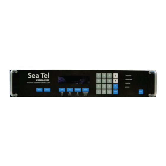
FOR SEA TEL DAC-2302 ANTENNA CONTROL UNIT
Antenna Serial Number: ________________________________
DAC-2302 Serial Number: _______________________________
Sea Tel, Inc.
4030 Nelson Avenue
Concord, CA 94520
Tel: (925) 798-7979
Fax: (925) 798-7986
Web: :
www.cobham.com\seatel
April 21, 2011
OPERATORS MANUAL
Sea Tel Inc doing business as Cobham SATCOM
Sea Tel Europe
Unit 1, Orion Industrial Centre
Wide Lane, Swaythling
Southampton, UK S0 18 2HJ
Tel: 44 (0)23 80 671155
Fax: 44 (0)23 80 671166
Web:
www.cobham.com\seatel
Document. No. 132628 Revision B
Advertisement
Table of Contents

Subscribe to Our Youtube Channel
Related Manuals for Sea Tel DAC-2302


Summary of Contents for Sea Tel DAC-2302
- Page 1 OPERATORS MANUAL FOR SEA TEL DAC-2302 ANTENNA CONTROL UNIT Antenna Serial Number: ________________________________ DAC-2302 Serial Number: _______________________________ Sea Tel, Inc. Sea Tel Europe 4030 Nelson Avenue Unit 1, Orion Industrial Centre Concord, CA 94520 Wide Lane, Swaythling Tel: (925) 798-7979...
- Page 2 All Rights Reserved. The information contained in this document is proprietary to Sea Tel, Inc.. This document may not be reproduced or distributed in any form without prior consent of Sea Tel, Inc. The information in this document is subject to change without notice. Copyright © 2010 Sea Tel, Inc is doing business as Cobham SATCOM.
-
Page 3: Table Of Contents
Table of Contents DAC2302 Operator Manual 1. QUICK START OPERATION – INTRODUCTION ........................1-1 1.1.................................... 1-1 UICK TART PERATION 1.2....................................1-1 RONT ANEL AYOUT 1.3..............................1-2 ASIC UNCTION OF RONT ANEL 1.4....................1-2 ASIC DESCRIPTION OF FRONT PANEL KEYS AND THEIR FUNCTIONS 1.5. - Page 4 DAC2302 Operator Manual Table of Contents This Page Intentionally Left Blank...
-
Page 5: Quick Start Operation - Introduction
Quick Start Operation – Introduction When power is turned ON, the ACU Display will initially show “SEA TEL INC - MASTER” and the ACU software version (ie DAC-2302 VER 7.xx ). 10 seconds later, the display will switch to “SEA TEL INC - REMOTE” and “INITIALIZING” for approximately two minutes while the Pedestal Control Unit (PCU) completes initialization of the antenna pedestal and then reports its Model &... -
Page 6: Basic Function Of Front Panel Keys
DAC2302 Operator Manual Quick Start Operation – Introduction 1.3. Basic Function of Front Panel Keys Keyboard operation is very simple and straightforward. Basic function of each key is: 1.4. Basic description of front panel keys and their functions The basic functions of the front panel keys, display and LEDs are: DISPLAY - 20 character x 2-line display of all menu display, entry, control and status windows. -
Page 7: Basic Description Of Front Panel Status Leds
Quick Start Operation – Introduction DAC2302 Operator Manual 1.5. Basic Description of Front Panel Status LEDs Status LED’s TRACKING - (Green LED) ON indicates that the ACU is Tracking a satellite signal whose AGC value is greater than the Threshold value AND contains the desired Network ID. - Page 8 DAC2302 Operator Manual Quick Start Operation – Introduction This Page Intentionally Left Blank...
-
Page 9: Operation
Operation DAC2302 Operator Manual Operation 2.1. Display & Entry Operation Menu The operation menus are arranged in four groups. Use the SHIP, SAT, ANTENNA and MODE keys to select their respective operation menu. Use the ENTER key to access the sub-menu of a selected group and then use the NSEW and ENTER keys to move up and down the sub-menu items. - Page 10 DAC2302 Operator Manual Operation Heading entry mode. Used to provide “True” Azimuth antenna position. If the GYRO TYPE parameter is NMEA0183 data or 1:1 Synchro, you will not be able to set HDG to any other value than it receives from the Ships Gyro Compass. For all other acceptable Gyro Compass input types the HDG MUST be initially set whenever the ACU power is turned ON.
-
Page 11: Sat Information Menus
Operation DAC2302 Operator Manual 2.1.2. SAT information menus. ou may press any one of the Main Menu keys at anytime to access its respective menu and their subsequent sub-menu’s The SAT Menu displays the current SAT and Signal Level information and consists of eight submenu selections. The NID displayed (while in full menu view) is the Network ID that is currently being received from the satellite that the antenna is currently pointed at. - Page 12 DAC2302 Operator Manual Operation Tracking Receiver entry mode. The individual settings of the Satellite Identification tracking receiver and the current signal level (AGC) will be displayed in each of the sub-menus below. Look at the label on the rear panel of your ACU to find out what receiver is has installed in it.
- Page 13 Operation DAC2302 Operator Manual Tone OFF AGC 1234 Press ENTER from the BAUD/KHz sub menu to access the TONE Sub Menu. Use the UP/DOWN arrow key to toggle 22 kHz Tone output on the rear panel “F” connector ON/OFF. ON is used to select High Band frequencies from the Multi- switch or LNB.
- Page 14 DAC2302 Operator Manual Operation NID #### AGC 1234 Press ENTER from the Forward Error Correction sub menu to access the Network ID Sub Menu. Used to enter the NID (or forced NID) of the satellite you want to The Network ID is a four digit HEX value. Enter 0000 if no NID is available, or to test for proper FREQ, BAUD &...
-
Page 15: Antenna Information Menus
Operation DAC2302 Operator Manual 2.1.3. ANTENNA information menus. ou may press any one of the Main Menu keys at anytime to access its respective menu and their subsequent sub-menu’s The ANTENNA Menu displays current pointing & polarization angles of the Antenna and consists of four submenu selections. - Page 16 DAC2302 Operator Manual Operation Elevation position/entry mode. Press ENTER from the Azimuth Sub menu to access the Elevation Sub Menu. This display represents the Elevation position of the antenna. Key in the desired numeric value of Elevation you want to target the antenna to and then press ENTER.
-
Page 17: Mode-Control And Status Menus
Operation DAC2302 Operator Manual 2.1.4. Mode-Control and Status Menus. ou may press any one of the Main Menu keys at anytime to access its respective menu and their subsequent sub-menu’s The Mode Menu display s diagnostic information pertinent to your antenna and consists of five submenu selections. -
Page 18: Setup Parameter Display And Entry Menus
DAC2302 Operator Manual Operation Status – Error menu. Press ENTER from the Search 2 Sub Menu to access the READ ONLY Status Error Sub Menu. LLLL - Comms Error Count - indicates the number of times that a Pedestal M&C communication message (between the ACU and PCU) was not received correctly. -
Page 19: Dishscan Operation
Operation DAC2302 Operator Manual 2.2.1. DishScan Operation To control tracking this system uses a variation of Conical scanning, called DishScan, which continuously drives the antenna in a very small diameter circle (defined by DishScan Amplitude) at 60 RPM. This circle is defined in 4 “quadrants”, UP, DOWN, LEFT, and RIGHT (by the DishScan Phase). -
Page 20: Inclined Orbit Search Pattern
DAC2302 Operator Manual Operation GYRO TYPE – must NOT be set to zero. SAT REF mode – may be ON if you are experiencing frequent, or constant, gyro read errors (error code 0001). Must be ON if you are using NMEA Gyro input. Target any satellite longitude value which includes even tenths digit values (ie SAT 101.0 W or SAT 101.2 W). -
Page 21: No Gyro Search Pattern
Operation DAC2302 Operator Manual SAT REF mode – may be ON if you are experiencing frequent, or constant, gyro read errors (error code 0001). Must be ON if you are using NMEA Gyro input. Target the desired satellite longitude value but include an odd tenths digit (ie if you desired to target inclined satellite 186.0 W you would key in SAT 186.1 W for the ACU to do an inclined search). -
Page 22: Auto-Polarization Operation
DAC2302 Operator Manual Operation 2.2. Auto-Polarization Operation If your antenna has the hardware to support it, another feature of the ACU is auto-polarization. When the Polang Type parameter set to a value of 72, the ACU automatically calculates the required polarization angle for the feed every 2 seconds based on ship's Latitude, Longitude and the Satellite Longitude. -
Page 23: Setup - Commif And Html
The Monitor and Control (M&C J3) port allows external control from a PC using a communications program such as Sea Tel’s ProgTerm or DacRemP via a straight 9 wire serial cable. This Port is used in conjunction with a diagnostic software connection to configure all communications settings, and/or for an Authorized Sea Tel Dealer to perform software uploads to the PCU, ACU Main PCB, and DVB Receiver. - Page 24 DAC2302 Operator Manual Setup – CommIF and HTML Pages Mouse Click on the Paper Clip icon and verify response to ACU status query similar to what’s shown. Mouse click on the Eyeball icon and verify response to ACU software version query. To View Communication settings type in DAC2202 Comm IF Commands: “[?↵”.
-
Page 25: Internal Html Page
Setup – CommIF and HTML Pages DAC2302 Operator Manual To change Communication Settings Type “[Control Codennn<cr>”. That’s left bracket, control code alpha/numeric digit, parameter, <carriage return> (No Spaces). Example: Change ACU IP address to 192.168.30.195 type: “[I192.168.30.195↵” Example: Change J2 NMEA Port B Baud Rate to 9600 type: “[B9600↵”... -
Page 26: System Information
DAC2302 Operator Manual Setup – CommIF and HTML Pages 3.3. System Information The System Information page, also known as the HOME page, displays current antenna software and model configurations. Number Description Click to select to the Port Settings Page. This page displays the TCP connection and baud rate settings for the Comm If Module. -
Page 27: Communication Port Settings
Setup – CommIF and HTML Pages DAC2302 Operator Manual 3.4. Communication Port Settings Number Description The IP Address field displays the Static Internet Protocol address value currently stored in the Comm IF module (Flash). To change the IP address to match an existing LAN info structure, type in the desired value and click on the SUBMIT button. - Page 28 DAC2302 Operator Manual Setup – CommIF and HTML Pages The M&C Baudrate field displays the J3 M&C Port Baud rate value currently stored in the Comm IF Module. To change the Baud rate, type in the desired value and click on the SUBMIT button or click on the SAVE button to store value to Flash.
-
Page 29: Dac Parameters
Setup – CommIF and HTML Pages DAC2302 Operator Manual 3.5. DAC Parameters Page 1 Number Description To change a parameter value mouse click inside the entry field and type in the desired value or select from the drop down list and click on the SUBMIT button. If the parameter value change(s) causes desirable operation click on the SAVE button to store into Flash. - Page 30 DAC2302 Operator Manual Setup – CommIF and HTML Pages The Gyro Type field displays the numeric value currently set in RAM. Select the desired Gyro Interface from the drop down menu selection list and the correlating parameter value for Gyro Type will be displayed in the entry field Click the SUBMIT button to transfer all currently displayed parameters to the operating software variables table (working memory).
-
Page 31: Status Page
Setup – CommIF and HTML Pages DAC2302 Operator Manual The Az Limit 4 field displays the numeric value currently stored in RAM. The Az Limit 5 field displays the numeric value currently stored in RAM. The Az Limit 6 field displays the numeric value currently stored in RAM. The EL Limit 12 field displays the numeric value currently stored in RAM. -
Page 32: Favorite Satellites Page
DAC2302 Operator Manual Setup – CommIF and HTML Pages The Azimuth field displays the Antenna’s True North Azimuth pointing angle. The Elevation field displays the Antenna’s Elevation pointing angle referenced to the horizon. The Relative AZ field displays the Antenna’s Azimuth pointing angle referenced to the vessels bow marker. - Page 33 Setup – CommIF and HTML Pages DAC2302 Operator Manual The FEC fields present the Forward Error Correction Rate for each respective Favorite Satellite Column. The Tone fields present the 22Khz Tone State for each respective Favorite Satellite Column. The Volt fields present the BDE voltage state for each respective Favorite Satellite Column. The Target NID fields present the Hexadecimal Network Identification value for each respective Favorite Satellite Column.
- Page 34 DAC2302 Operator Manual Setup – CommIF and HTML Pages This Page Intentionally Left Blank 3-12...
Need help?
Do you have a question about the DAC-2302 and is the answer not in the manual?
Questions and answers