Table of Contents
Advertisement
INSTRUCTIONS-PARTS LIST
50 Hz, 220/240 Volts, 0.5 Amp
PT2000 Pressure Roller System
17.5 bar (250 psi) MAXIMUM WORKING PRESSURE
Model 220–240, Series E
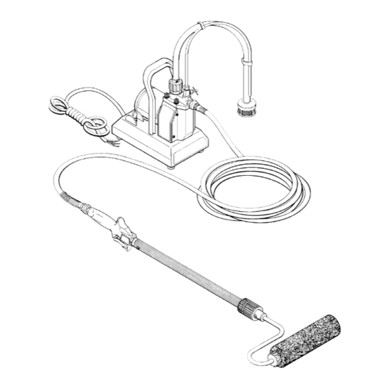
Complete System
with hose, roller valve, extension and roller
Model 221–076, Series E
Basic System
without hose, roller valve, extension or roller
PATENT NO, 4,652,024
GRACO INC. P.O. BOX 1441 MINNEAPOLIS, MN 55440–1441
This manual contains IMPORTANT
INSTRUCTIONS and WARNINGS.
READ AND RETAIN FOR REFERENCE.
COPYRIGHT 1986, GRACO INC.
307–760
Rev G
Supersedes E
Advertisement
Chapters
Table of Contents

Related Manuals for Graco 220-240


Summary of Contents for Graco 220-240
- Page 1 INSTRUCTIONS-PARTS LIST 50 Hz, 220/240 Volts, 0.5 Amp PT2000 Pressure Roller System 17.5 bar (250 psi) MAXIMUM WORKING PRESSURE Model 220–240, Series E Complete System with hose, roller valve, extension and roller Model 221–076, Series E Basic System without hose, roller valve, extension or roller PATENT NO, 4,652,024 GRACO INC.
-
Page 2: Table Of Contents
TABLE OF CONTENTS Terms ..........Warnings . -
Page 3: Pt2000 Pressure Roller System Description
PT2000 PRESSURE ROLLER SYSTEM DESCRIPTION SUCTION TUBE PRIMING TUBE INLET VALVE MOTOR ON/OFF SWITCH POWER SUPPLY CORD Add plug according to local code SPRING GUARD MUST BE AT THIS END ROLLER VALVE Fig 1 Motor The motor drives the connecting rod which moves the diaphragm. -
Page 4: Setup
SUCTION TUBE PRIMING TUBE INLET VALVE MOTOR ON/OFF SWITCH POWER SUPPLY CORD Add plug according to local code SPRING GUARD MUST BE AT THIS END USE TWO WRENCHES TO TIGHTEN ROLLER VALVE TRIGGER USE TWO WRENCHES TO TIGHTEN Fig 2 CAUTION To avoid premature wear of the pressure switch, never use more than 7.6 m (25 ft) of 1/4 in. -
Page 5: Operation
1. Place the suction tube in the pail of paint. 2. Plug in the sprayer. 3. Open the priming valve 2 turns counterclockwise. 4. Turn the ON/OFF switch ON. 5. You can see the paint being drawn into the suction tube (if the tube is clean). -
Page 6: Maintenance
CAUTION Thorough flushing and proper maintenance are es- sential to keep your system working properly Improper flushing or maintenance may prevent the system from working the next time you need it, and may result in costly damage to the system. ALWAYS flush your system thoroughly and immedi- ately after each use. -
Page 7: Installing & Removing A Roller Cover
Installing and Removing a Roller Cover (See Fig 4) 1. To install a cover, hold the diffuser and unscrew the retainer nut. Slide the cover over the diffuser assem- bly and reinstall the nut. Do not overtighten the nut. 2. To remove a cover, hold the cover and unscrew the retainer nut. -
Page 8: Troubleshooting Guide
WARNING Pressure Relief Procedure To reduce the risk of serious bodily injury, including injury from moving parts or electric shock, always follow this procedure whenever you shut off the sys- tem, when checking or servicing any part of the sys- tem, and whenever you stop painting. - Page 9 Roller Valve WARNING Always follow the Pressure Relief Procedure Warning on page 8 before attempting any repair. NOTE: Order repair kit no. 218–960 to repair this roller valve. 1. Tap out the pin (A) and slide the trigger (B) off of the valve.
-
Page 10: Power Supply Cord
WARNING These repair procedures should be performed only by qualified repair personnel with an electrical back ground, using the proper tools. Failure to do the pro- cedures correctly can result in electric shock, or oth- er serious injury and damage to the pump. WARNING Always follow the Pressure Relief Procedure Warning on page 8 before attempting any repair. -
Page 11: Pressure Switch
Pressure Switch (See Fig 1 1, 12 & 13) 1. Disconnect the pressure switch leads from the ON/ OFF switch and from the rectifier. See Fig 11. 2. Remove the front cover (23). See Fig 13. 3. Unscrew the retainer (14) and remove the pressure switch (12) and o–ring (12a). -
Page 12: Priming Valve & Tube
Diaphragm (See Fig 14) CAUTION To avoid leaks and costly pump damage, replace the diaphragm whenever the pump housing (9) is re- moved or after each 100 hours of use, whichever comes first. During use, small grooves are formed in the diaphragm which cannot be realigned properly. - Page 13 Connecting Rod and Bearing (See Fig 16) 1. Remove the front cover plate (23). Remove the screws (15) and tip the pump housing (9) out of the way. Unscrew the diaphragm (17) and discard. CAUTION Replace the diaphragm (17) whenever you remove the pump housing (9).
- Page 14 Model 221–076, Series E Basic System Includes items 2 – 54 and 65 – 87 Model 220–240, Series E Complete System Includes items 2 – 87 NOTE: See Wiring Schematic on page 15. 307–760 PARTS DRAWING LUBRICATE THREADS TORQUE TO 9.6 N.m (85 in-lb) See Detail A,...
-
Page 15: Parts List
PRESSURE ROLLER SYSTEM Model 220–240, Series E Complete System Includes items 2–87 NOTE: Part numbers and drawings for items 2, 3, 4, 9, 12, 14, and 55 – 64 are given on pages 16 and 17. NO. PART NO. DESCRIPTION 218–973* PRIMING VALVE KIT 181–152... -
Page 16: Parts Drawing
NO. PART NO. DESCRIPTION 220–970 OUTLET VALVE KIT Includes items 2a–2f 222–349 .FITTING, outlet 180–454 .GASKET 107–521 .SPRING 101–956 .BALL 218–968 .HOUSING, seat, valve 180–455 .SEAL, washer 220–931* INLET VALVE KIT Includes replaceable item 4 183–419 .GASKET 181–146 HOUSING, pump 218–974 PRESSURE SWITCH KIT Includes item 12a... -
Page 17: Threads
DETAIL A Pump Housing Parts APPLY THREAD SEALANT TORQUE TO 6.2–7.4 N.m (55–65 in-lb DISPENSING ACCESSORIES Not included with Basic System 221–076 SEE PARTS DETAIL ON PAGE 16 PARTS DRAWING Ref 10 TORQUE TO 13.5–16 N.m (120–140 in-lb TORQUE TO 32–34 N.m (280–300 in-lb SEE PARTS DETAIL ON PAGE 16... -
Page 18: Accessories
Must be purchased separately . CAUTION To avoid premature wear of the pressure switch, never use more than 7.6 m (25 ft) of 6 mm (1/4 in.) ID outlet hose. When longer outlet hose is needed use 9 mm (3/8 in.) ID hose at a maximum of 30 m (100 ft) long. - Page 19 SERVICE INFORMATION Listed below by the assembly changed are OLD, NEW, ADDED and DELETED parts. OLD and NEW parts are interchangeable. ADDED and DELETED parts may not be interchangeable individually. Assembly Part Part No. Changed Status 220–970 220–952 Outlet Valve 222–349 220–240 220–930...
-
Page 20: Technical Data
Maximum Operating Pressure Power Requirements ....Pump Output ........Power Supply Cord .
Need help?
Do you have a question about the 220-240 and is the answer not in the manual?
Questions and answers