Table of Contents
Advertisement
Quick Links
GLOBALSAT GPS Engine Board
Hardware Data Sheet
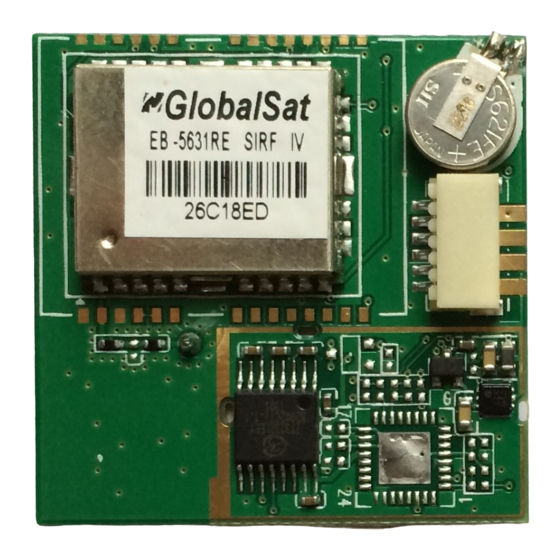
Product No : EB-5631RE
Version 1.2
GlobalSat Technology Corporation
16F., No. 186, Jian-Yi Road, Chung-Ho City, Taipei
Hsien 235, Taiwan
Tel: 886-2-8226-3799 Fax: 886-2-8226-3899
E-mail :
service@globalsat.com.tw
Website:
www.globalsat.com.tw
Issue Date
APPR
CHECK
PREPARE
Ray
Luwalk
2012/7/30
2012/7/30
- 1 -
Advertisement
Table of Contents

Subscribe to Our Youtube Channel
Related Manuals for Globalsat EB-5631RE


Summary of Contents for Globalsat EB-5631RE
- Page 1 GLOBALSAT GPS Engine Board Hardware Data Sheet Product No : EB-5631RE Version 1.2 GlobalSat Technology Corporation 16F., No. 186, Jian-Yi Road, Chung-Ho City, Taipei Hsien 235, Taiwan Tel: 886-2-8226-3799 Fax: 886-2-8226-3899 E-mail : service@globalsat.com.tw Website: www.globalsat.com.tw Issue Date APPR CHECK...
-
Page 2: Product Description
Product Description Product Description EB-5631RE GPS module features high sensitivity, low power and ultra small form factor. This GPS module is powered by SiRF Star IV, it can provide you with superior sensitivity and performance even in urban canyon and dense foliage environment. With SiRF CGEE (Client Generated Extended Ephemeris) technology, it predicts satellite positions for up to 3 days and delivers CGEE-start time of less than 15 seconds under most conditions, without any network assistance. - Page 3 (For example, control LED) TIMEMARK One pulse per second output.(1PPS) ON_OFF pin is used to command the ON_OFF EB-5631RE to turn on or off WAKE_UP System power on, 1.8V output . This is the main transmits channel for outputting navigation and measurement data to user’s navigation software or user...
-
Page 4: Electrical Specification
OFF command is a software feature based on interrupts related to rising and/or falling edges and/or sensing of pin levels. 3. The WAKE_UP pin is an output from the EB-5631RE used to enable an external PMIC. A low on this output indicates that the EB-5631RE is in one of its low-power states (KA-only, Hibernate, or Standby mode) and requires no more than 60μA of current on the VIO_18 input. -
Page 5: Dc Electrical Characteristics
DC Electrical characteristics Parameter Symbol Min. Typ. Max. Conditions Units High Level Input Voltage 0.7*VCC Low Level Input Voltage -0.4 0.45 High Level Output Voltage 0.75*Vgcc Vgcc Low Level Output Voltage High Level Output Current Low Level Output Current Vgcc is SiRF Star IV Chip power input, 1.8V Vin. Receiver Performance -163dBm Tracking :... - Page 6 Environmental Characteristics Parameter Unit Humidity Range % non-condensing Operation Temperature ℃ Storage Temperature ℃ Physical Characteristic Unit: mm Type 36-pin stamp holes Dimensions 15.9 mm * 13.1 mm * 2.7mm ±0.2mm 2012/7/30 - 6 -...
-
Page 7: Application Circuit
2K2/NC 2K2/NC I2C_SCL I2C_SDA GPS_ANTENNA 50 Ohm Micro strip line 50ohm LINE RF IN CHOKE RF WAKE_UP WAKE_UP CAP NP CAP NP EB-5631RE ON_OFF VBAT ON_OFF 10K/NC GPS_3V3 VBAT TIMEMAEK 10UF 10UF 1PPS OUTPUT GPIO RESET GPS Active Antenna Specifications (Recommendation) Frequency: 1575.42 + 2MHz... - Page 8 External Interrupts. If don’t use this, just NC. 5. WAKE_UP: EB-5631RE power on, WAKE_UP will output 1.8V. 6. ON_OFF: This pin is controlled EB-5631RE power on. If EB-5631RE want to EB-365 pin to pin compactable, please ON_OFF connect to WAKE_UP. If don’t use this, just NC.
-
Page 9: Operating Description
System power controller, when EB-5631RE board. (3.1Vdc to 3.5Vdc) Power ON, this pin will output 1.8V RESET Low Active, when EB-5631RE is accepted this This is the main transmits channel for single, EB-5631RE going to Hibernate mode. If outputting navigation and measurement data want EB-5631RE up, need input ON_OFF to user’s navigation software or user written... - Page 10 SOFTWARE COMMAND NMEA Output Command GGA - Global Positioning System Fixed Data Note – Fields marked in italic apply only to NMEA version 2.3 (and later) in this NMEA message description Table B-2 contains the values for the following example: $GPGGA,161229.487,3723.2475,N,12158.3416,W,1,07,1.0,9.0,M,-34.2,M,,0000*18 Table B-2 GGA Data Format Name...
- Page 11 Note: A valid status is derived from all the parameters set in the software. This includes the minimum number of satellites required, any DOP mask setting, presence of DGPS corrections, etc. If the default or current software setting requires that a factor is met, then if that factor is not met the solution will be marked as invalid.
- Page 12 GSA - GNSS DOP and Active Satellites Table B-5 contains the values for the following example: $GPGSA,A,3,07,02,26,27,09,04,15,,,,,,1.8,1.0,1.5*33 Table B-5 GSA Data Format Name Example Units Description Message ID $GPGSA GSA protocol header Mode 1 See Table B-6 Mode 2 See Table B-7 Satellite Used Sv on Channel 1 Satellite Used...
-
Page 13: Gsv - Gnss Satellites In View
GSV - GNSS Satellites in View Table B-8 contains the values for the following example: $GPGSV,2,1,07,07,79,048,42,02,51,062,43,26,36,256,42,27,27,138,42*71 $GPGSV,2,2,07,09,23,313,42,04,19,159,41,15,12,041,42*41 Table B-8 GSV Data Format Name Example Units Description Message ID $GPGSV GSV protocol header Number of Messages Range 1 to 3 Message Number Range 1 to 3 Satellites in View Satellite ID... - Page 14 RMC - Recommended Minimum Specific GNSS Data Note – Fields marked in italic apply only to NMEA version 2.3 (and later) in this NMEA message description Table B-9 contains the values for the following example: $GPRMC,161229.487,A,3723.2475,N,12158.3416,W,0.13,309.62,120598,,,A*10 Table B-9 RMC Data Format Name Example Units...
- Page 15 VTG - Course Over Ground and Ground Speed Note – Fields marked in italic apply only to NMEA version 2.3 (and later) in this NMEA message description Table B-10 contains the values for the following example: $GPVTG,309.62,T,,M,0.13,N,0.2,K,A*23 Table B-10 VTG Data Format Name Example Units...
- Page 16 ZDA - Time and Date This message is included only with systems which support a time-mark output pulse identified as "1PPS". Outputs the time associated with the current 1PPS pulse. Each message is output within a few hundred ms after the 1PPS pulse is output and tells the time of the pulse that just occurred. Table B-11 contains the values for the following example: $GPZDA,181813,14,10,2003,,*4F<CR><LF>...
- Page 17 NMEA Input Command A). Set Serial Port ID: 100 Set PORTA parameters and protocol This command message is used to set the protocol (SiRF Binary, NMEA, or USER1) and/or the communication parameters (baud, data bits, stop bits, parity). Generally, this command would be used to switch the module back to SiRF Binary protocol mode where a more extensive command message set is available.
- Page 18 Format: $PSRF101,<X>,<Y>,<Z>,<ClkOffset>,<TimeOfWeek>,<WeekNo>,<chnlCount>,<ResetCfg>*CK SUM<CR><LF> <X> X coordinate position INT32 <Y> Y coordinate position INT32 <Z> Z coordinate position INT32 <ClkOffset> Clock offset of the receiver in Hz, Use 0 for last saved value if available. If this is unavailable, a default value of 75000 for GSP1, 95000 for GSP 1/LX will be used.
- Page 19 the parameters will be stored in battery backed SRAM and then the receiver will restart using the saved parameters. Format: $PSRF102,<Baud>,<DataBits>,<StopBits>,<Parity>*CKSUM<CR><LF> <baud> 1200,2400,4800,9600,19200,38400 <DataBits> <StopBits> <Parity> 0=None, Odd=1,Even=2 Example: Set DGPS Port to be 9600,8,N,1 $PSRF102,9600,8,1.0*12 D). Query/Rate Control ID: 103 Query standard NMEA message and/or set output rate This command is used to control the output of standard NMEA message GGA, GLL, GSA, GSV, RMC, VTG.
- Page 20 Example 1: Query the GGA message with checksum enabled $PSRF103,00,01,00,01*25 Example 2: Enable VTG message for a 1Hz constant output with checksum enabled $PSRF103,05,00,01,01*20 Example 3: Disable VTG message $PSRF103,05,00,00,01*21 E). LLA Navigation lnitialization ID: 104 Parameters required to start using Lat/Lon/Alt This command is used to initialize the module for a warm start, by providing current position (in Latitude, Longitude, Altitude coordinates), clock offset, and time.
- Page 21 Example: Start using known position and time. $PSRF104,37.3875111,-121.97232,0,96000,237759,922,12,3*37 F). Development Data On/Off ID: 105 Switch Development Data Messages On/Off Use this command to enable development debug information if you are having trouble getting commands accepted. Invalid commands will generate debug information that should enable the user to determine the source of the command rejection.
-
Page 22: Recommended Layout Pad
PCB Layout Recommend Recommended Layout PAD Unit: mm Tolerance: 0.1mm PCB Layout Recommendations Do not routing the other signal or power trace under the engine board. This pin receives signal of GPS analog via external active antenna .It has to be a controlled impedance trace at 50ohm. -
Page 23: Recommended Reflow Profile
Recommended Reflow Profile: Pre heating temperature: Pre heating time: 90±30[sec.] 150±10[℃] Heating temperature: Heating time: 10±1[sec.] 235±5[℃] Peak temperature must not exceed 240℃ and the duration of over 200℃ should be 30±10 Seconds. 2012/7/30 - 23 -... -
Page 24: Function Description
1PPS output = 200mS. EB-5631RE EB-5631RE default is open Static Mode; close SBAS; B/R setting 9600; NMEA output is GGA, GSA, GSV, RMC, VTG, GLL and ZDA. Output rate is 1 message per 1 second. GPS is not 3D Fixes, the GPIO5 is LO output, 3D Fixed is Flash output, or other GPS feature and NMEA output feature.
Need help?
Do you have a question about the EB-5631RE and is the answer not in the manual?
Questions and answers