Datalogic Jet User Manual
Hide thumbs
Also See for Jet:
- User manual (121 pages) ,
- Quick start manual (2 pages) ,
- User manual (2 pages)
Table of Contents
Advertisement
Quick Links
Download this manual
See also:
User Manual
Advertisement
Table of Contents

Related Manuals for Datalogic Jet


Summary of Contents for Datalogic Jet
- Page 1 JET™ User’s Manual...
- Page 3 Jet™ USER'S MANUAL...
- Page 4 ALL RIGHTS RESERVED Datalogic reserves the right to make modifications and improvements without prior notification. Datalogic shall not be liable for technical or editorial errors or omissions contained herein, nor for incidental or consequential damages resulting from the use of this material.
-
Page 5: Table Of Contents
CONTENTS DATALOGIC END USER LICENSE AGREEMENT ........v REFERENCES ................... vii Conventions ....................vii Reference Documentation ................vii Service and Support ..................vii SAFETY REGULATIONS................viii General Safety Rules.................. viii Laser Safety....................ix Radio Compliance..................xii Information for the User ................xiii GENERAL VIEW ..................xiv INTRODUCTION .................. - Page 6 Data Capture Configuration ................ 22 3.6.1 Configure ....................22 3.6.2 Capture ....................... 26 Control Panel ....................27 3.7.1 Buttons......................28 3.7.2 Registry....................... 28 3.7.3 Files Admin ....................29 3.7.4 Wireless Communications................31 3.7.5 Bluetooth® Manager Device Setup............. 32 Windows Connections................. 34 3.8.1 Microsoft®...
-
Page 7: Datalogic End User License Agreement
Software and has paid the applicable fee for the upgrade, if required; (2) use of upgrades is limited to Datalogic equipment for which customer is the original end user, purchaser or lessee or who otherwise holds a valid license to use the Software which is being upgraded;... - Page 8 Period” means a period beginning on the date of Customer’s receipt of the Software and ending on the later of (a) ninety (90) days from the date of initial shipment of the Software by Datalogic, or (b) the end of the minimum period required by the law of the applicable jurisdiction.
-
Page 9: References
For further information regarding Jet™ refer to the SDK Help on-Line. SERVICE AND SUPPORT Datalogic provides several services as well as technical support through its website. Log on to www.datalogic.com and click on the links indicated for further information including: PRODUCTS Search through the links to arrive at your product page where you can download specific Manuals and Software &... -
Page 10: Safety Regulations
Any tampering will invalidate the warranty. When replacing the battery pack or at the end of the operative life of the Jet™ PDA, disposal must be performed in compliance with the laws in force. -
Page 11: Laser Safety
LASER SAFETY The laser light is visible to the human eye and is emitted from the window indicated in the figure. This information applies to both Laser models and the JET™ Imager Aiming System. Laser output window This product complies with... - Page 12 ENGLISH The following information is provided to comply with the rules imposed by international authorities and refers to the correct use of your PDA. STANDARD LASER SAFETY REGULATIONS This product conforms to the applicable requirements of both CDRH 21 CFR 1040 and EN 60825-1 at the date of manufacture.
- Page 13 DEUTSCH Die folgenden Informationen stimmen mit den Sicherheitshinweisen überein, die von internationalen Behörden auferlegt wurden, und sie beziehen sich auf den korrekten Gebrauch vom PDA. NORM FÜR DIE LASERSICHERHEIT Dies Produkt entspricht am Tag der Herstellung den gültigen EN 60825-1 und CDRH 21 CFR 1040 Normen für die Lasersicherheit.
-
Page 14: Radio Compliance
Además, eviten de dirigir el rayo láser hacia los ojos de un observador, también a través de superficies reflectantes como los espejos. LED Illuminator The use of an illuminator in the JET™ Imager is a Class 1 LED product: IlIuminator Class 1 LED product ILLUMINATORE LED CLASSE 1... -
Page 15: Information For The User
The following shows the correspondence between the Jet™ models and the Radio modules: Jet™ 5XX-XXX 802.11b (Wi-Fi) radio card Jet™ X1X-XXX GSM/GPRS Tri-band (900, 1800, 1900 MHz) module Jet™ 51X-XXX 802.11b (Wi-Fi) radio card + GSM/GPRS Tri-band (900, 1800, 1900 MHz) module... -
Page 16: General View
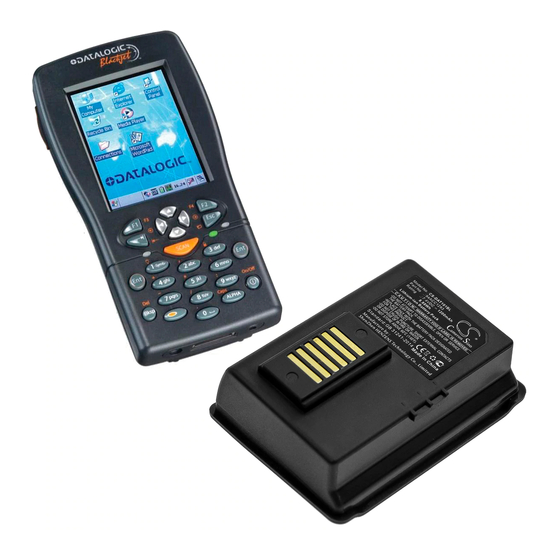
GENERAL VIEW A) Data capture/Laser Output window Backlit display B) Scan Key(s) (3) K) Adjustable elastic strap with stylus C) Bluetooth® LED holder D) Charging status LED Microphone E) Backlit keyboard M) Latch release button External Power Supply Connector N) Battery latch G) Communication/Charger Connector O) Battery pack H) Headset jack... -
Page 17: Introduction
AVAILABLE MODELS The brand new Datalogic JET™ PDA can be equipped with several data capture and data communication options: as a result it will be available in 12 different models. -
Page 18: Package Contents
1 adjustable elastic strap with stylus holder 1 belt clip 1 belt clip pivot Any other packages will contain the accessories necessary for the Jet™ PDA connection to the host computer and to the network: the cradle, power supply, and one or more connection cables. -
Page 19: Accessories
94ACC1297 PG12-10P35 AC/DC Power supply UK KIT 94ACC1298 PG12-10P35 AC/DC Power supply US KIT 94ACC1299 PG12-10P35 AC/DC Power supply AUS KIT 94ACC4595 FPS18 Power Supply without cord for Jet™ Single Cradle Desk and for Jet™ Multi-Battery Charger 94ACC1150 Power cord EU 3-pin... -
Page 20: Connections
JET™ CONNECTIONS PDA CONNECTION TO THE HOST COMPUTER 2.1.1 RS232/USB Direct Connection You can use a cable to connect the Jet™ PDA to a host computer to transfer data. Key: Host computer RS232 cable or USB cable Jet™ PDA *Power Supply... -
Page 21: 2.1.2 Wlan Connection
CONNECTIONS 2.1.2 WLAN Connection Jet™ Wi-Fi models can communicate with the host using the on-board radio frequency module and an Access Point connected to the host computer. Key: A) Jet™ PDA B) Access point In order to avoid wasting power, the Wi-Fi module is off by default. If you need to have the Wi-Fi module working, the module must be powered on using the Wireless Communications applet (see par. -
Page 22: Wpan Connections
JET™ 2.1.3 WPAN Connections ® Jet™ PDAs can communicate with a Bluetooth device, such as a printer, within a ® range of 10 m, using the on-board Bluetooth module. Key: A) Jet™ PDA ® B) Bluetooth printer In order to avoid wasting power, the Bluetooth® module is off by default. -
Page 23: Wwan Connections
CONNECTIONS 2.1.4 WWAN Connections JET GSM/GPRS models enhance your connectivity solutions giving you an opening to an international wireless infrastructure that is the standard in Europe and Asia. GSM (Global System for Mobile communications), is a digital mobile phone system based on TDMA;... -
Page 24: Installing The Sim Card
Installing the SIM Card SIM Card Slot Locking Plate To correctly insert the SIM Card, proceed as follows: Turn off the Jet™ PDA. Press the latch release button and pull the battery latch down as indicated in the figure below:... -
Page 25: Removing The Sim Card
CONNECTIONS After removing the battery pack, open the Sim Card slot by pulling up the locking plate. Pull up the card holder and insert the Sim Card with its contacts downwards and its round corner at the bottom. Lock the card into place by pushing the card holder down and then pulling the locking plate down. -
Page 26: Connection Cables
JET™ CONNECTION CABLES The following cables are listed with their order number. RS232 Direct Connection: 94A051008 WIN-NET SERIAL CABLE (HRS 3500-16P-CV) JET™ side HOST/PC side 16-pin 9-pin (female) USB Direct Connection: 94A051009 WIN-NET USB CABLE (HRS 3500-16P-CV) JET™ side HOST/PC side... -
Page 27: Use And Functioning
PDA STARTUP The JET™ PDA turns on when the battery pack or the external supply is inserted. After the battery pack is installed, use the [ON/OFF] key to turn the PDA on and off. -
Page 28: Using The Stylus
JET™ The PDA goes into power-off (low power with display and keyboard backlight off), when it is no longer used for more than a programmable timeout, which is defined in the POWER applet of the Control Panel. In this mode it can be awakened (resuming operation) by the [ON/OFF] key. -
Page 29: Data Capture
3.3.1 Laser Data Capture To scan barcodes, point the JET™ PDA laser model onto the code from a distance within the reading range while pressing one of the three SCAN Keys. See the reading diagrams in par. 5.2 for the reading range of your model. -
Page 30: Imager Data Capture
3.3.2 Imager Data Capture To read a 1D or 2D code, simply point the JET™ Imager model onto the code from a distance within the reading range (See par. 5.1, section Jet™ Imager Optical Features) and press one of the three SCAN Keys. -
Page 31: Rfid Data Capture
3.3.3 RFID Data Capture To read or write a tag, place the JET™ PDA so that the RFID emission window is in front of and almost in contact with the tag, then press one of the three SCAN Keys or... -
Page 32: Description Of The Keys
JET™ DESCRIPTION OF THE KEYS The JET™ PDA provides a keyboard having a total of 27 keys. The keyboard can be divided as follows: 2 Lateral SCAN keys (1 per side) System Control Navigation Keys Power Key General keys 3.4.1 System Control and Navigation Keys Powers the PDA ON or OFF. -
Page 33: Key Selection
By pressing these keys simultaneously, a system software reset is performed. SCAN By pressing these keys simultaneously, a system hardware reset is performed. SCAN 3.4.2 Key Selection The following figure shows the JET™ keyboard: Start SCAN -Symb- Enter Enter pqrs wxyz... - Page 34 JET™ Some of these keys carry extra symbols and are logically divided in up to 3 sections according to the following figure: Each section corresponds to a symbol that can be obtained using the corresponding keyboard method according to the following scheme: A) function of the key when simultaneously pressed along with the Blue key;...
- Page 35 USE AND FUNCTIONING It enters a special mode through which it is possible to digit all the alphabetic characters positioned over the keys. Ex: 7pqrs in alphanumeric mode: press once for ‘p’, twice ALPHA for ‘q’, three times for ‘r’, four times for ‘s’. To exit the Alpha mode and return to the keyboard normal functioning it is necessary to press the Alpha key again.
-
Page 36: Status Indicators
JET™ STATUS INDICATORS 3.5.1 LED Status The JET™ provides three different LEDs signaling the PDA status. STATUS General Purpose Green/Red This LED is available to the application (left-side) program. ® Blue blinking ® Bluetooth it blinks when the Bluetooth module is... -
Page 37: Status Bar
USE AND FUNCTIONING 3.5.2 Status Bar The Status Bar provides information about the time, the battery level, the keyboard function, and the decoding status. ICONS DESCRIPTION Time and Battery Icons It shows the time They are representative of five different icons indicating the battery level. -
Page 38: Data Capture Configuration
JET™ DATA CAPTURE CONFIGURATION From the Taskbar, tap the "Data Capture" icon to open a drop–down menu. Data Capture can also be accessed from the Control Panel. By selecting the Info item from this drop-down menu you can access information about the Scanner and the Software;... - Page 39 USE AND FUNCTIONING Data Capture Configuration Window The screen format shows two columns where the left column indicates branches or parameters. Branches have three dots in the right column (...). You can navigate through the tree structure using the stylus or keyboard arrows directly on the item field or from the menu.
-
Page 40: Reader Parameters
JET™ Alternatively using the stylus, you can tap once directly on the value on the right column, continue tapping until the desired value is reached. To activate a new configuration select the File ->Save Menu to send the new configuration to the barcode decoding software and save the new configuration. This will save the configuration to non-volatile memory preventing loss at the next system reset. -
Page 41: Default Settings
USE AND FUNCTIONING Default Settings The following tables contain the default values for the major barcode setup parameters, according to the type of scan engine mounted on the PDA. For a complete list of parameters and of their configuration procedures, please refer to the SDK Help file on the CD. -
Page 42: Capture
JET™ BARCODE SYMBOLOGY HP Laser Imager RFID+Laser SPECIFIC READER PARAMETERS Enabled Disabled Plessey Disabled Code 93 Disabled Enabled Disabled Code 11 Disabled PDF - 417 Enabled Data Matrix Enabled Enabled POSTNET PLANET Japan Post Disabled* Australia Post KIX Code Royal Mail Code (RM4SCC) *These codes may be enabled individually but are disabled as a group. -
Page 43: Control Panel
USE AND FUNCTIONING Data Capture can also be enabled through the Configuration applet by selecting File ->Scanner from the main menu, or by enabling the parameter Scan Always On in the Scan Parameters branch. Enabling the Data Capture CONTROL PANEL From the Desktop, double tap on the "Control Panel"... -
Page 44: Buttons
JET™ 3.7.1 Buttons The BUTTONS Applet allows assigning desired applications to be launched by the Act button or one of the function keys (F1, F2, F3). 3.7.2 Registry The REGISTRY ADMIN applet provides management of Windows CE .NET registry. Select the REGISTRY ADMIN applet by double tapping the Registry Admin icon. -
Page 45: Files Admin
USE AND FUNCTIONING 3.7.3 Files Admin The FILES ADMIN applet enables control of the permanence of files in the System Folder. Two functions are available on the Files Admin Main window by means of two buttons: Files Admin Main Window Save Session: with this button all files will be permanently saved in the \Windows directory in non-volatile memory. - Page 46 JET™ Safe Setup First Mask Then select \Windows or a relevant sub-directory in the path box. Then, Safe Setup will recognize the new files and directories present in the \Windows directory, and will copy them to the \Backup\Windows directory. At the next hardware reset, these files will be restored (see par.
-
Page 47: 3.7.4 Wireless Communications
USE AND FUNCTIONING 3.7.4 Wireless Communications The WIRELESS COMMUNICATIONS applet provides management of the Wi-Fi ® Card and of the Bluetooth and GSM/GPRS modules. Select the WIRELESS COMMUNICATIONS applet by double tapping the Wireless Communications icon. The following window will appear: Wireless Communications Window In order to avoid wasting power, all modules are off by default. -
Page 48: Bluetooth® Manager Device Setup
® Enable the Bluetooth module as described in par. 3.7.4. ® Place the Bluetooth device within the range of the JET™ PDA (10 meters). ® From the JET™Control Panel, select and run the Bluetooth Device Properties applet. Run the Discovery procedure: "Scan Device". The following window will appear:... - Page 49 USE AND FUNCTIONING Select the discovered device and check "Trusted" in the menu. Activate the trusted device by checking "Active". ® Close the Bluetooth Manager by selecting OK.
-
Page 50: Windows Connections
JET™ PDA and synchronize the information on them. Synchronization compares the data on the JET™ PDA with that on the desktop computer and updates both computers with the most recent information. - Page 51 You can establish a connection by Serial cable, by USB cable or by network. Moreover, if you have a JET™ Single Cradle you can connect your JET™ PDA putting it into the cradle and using a standard A-B USB cable or a standard Serial null modem cable.
-
Page 52: Backup Directory File Management
JET™ BACKUP DIRECTORY FILE MANAGEMENT All of the Windows CE .NET system files reside in RAM (volatile memory) except for the Backup directory, which resides in FLASH (non-volatile memory). Therefore the contents of the Backup directory are persistent even if the PDA is re-booted or the battery pack is changed. -
Page 53: Maintenance
It is possible to recharge the battery pack by using the PG12-10P35 AC/DC external power supply directly connected to the Jet™ PDA, see par. 2.1.1. Alternatively, it is also possible to recharge the battery pack by using the Jet™ Single Cradle Desk or the Jet™ Single Cradle Vehicle. -
Page 54: Replacing The Battery Pack
JET™ REPLACING THE BATTERY PACK To correctly replace the battery pack, proceed as follows. Turn off the Jet™ PDA. Press the latch release button and pull the battery latch down as indicated in the figure below: Remove the battery pack. -
Page 55: Cleaning The Pda
(when pressing the ON button). In this case, either substitute the battery pack with a charged one NOTE (>50%) or insert Jet™ into a powered cradle or plug it into the direct power supply. CLEANING THE PDA Periodically clean the Jet™ PDA with a slightly dampened cloth. -
Page 56: Technical Features
JET™ TECHNICAL FEATURES TECHNICAL DATA Jet™ Common Features Electrical Features Power DC supply 14 V ± 5% Battery pack 2 cell Li-Ion 1070 mAh@ 7.4 V (nominal) Large capacity pack 2 cell Li-Ion 1800 mAh@ 7.4 V (nominal) Internal backup battery Rechargeable Li-Ion 30 mAh Communication Features Windows CE.NET COM Port... - Page 57 Decoded barcodes 2D PDF417, DataMatrix , QR Postal codes POSTNET, PLANET, Japan Post, Australia Post, KIX Code, Royal Mail Code (RM4SCC) Jet™ HP Laser / RFID +Laser Optical Features Optical Features Jet™ HP Laser Jet™ RFID +Laser Maximum resolution 0.13 mm / 5 mils 0.13 mm / 5 mils...
- Page 58 JET™ Jet™ Imager Optical Features Optical Features Max. resolution 1D Codes 0.10 mm / 4 mils 2D Codes 0.17 mm / 6.6 mils Skew angle ± 40 ° Pitch angle ± 35° Depth of field* 1D (linear): X-dimension Symbol size...
-
Page 59: Reading Diagrams
TECHNICAL FEATURES READING DIAGRAMS Jet™ HP Laser Reading Zones (10° skew 1.00 mm (40 mils) 0.50 mm (20 mils) 0.38 mm (15 mils) 0.25 mm (10 mils) 0.19 mm (7.5 mils) 0.13 mm (5 mils) 0.33 mm (13 mils) 800 mm Jet™... -
Page 60: Test Codes
JET™ TEST CODES High Density Codes 0.25 mm (10 mils) Code 39 17162 2/5 Interleaved 0123456784 Code 128 test EAN 13 EAN 8... - Page 61 TEST CODES Medium Density Codes 0.38 mm (15 mils) Code 39 17162 Interleaved 2/5 0123456784 Code 128 test 100% EAN 13 100% EAN 8...
- Page 62 JET™ Low Density Codes 0.50 mm (20 mils) Code 39 17162 Interleaved 2/5 0123456784 Code 128 test 120% EAN 13 120% EAN 8...
-
Page 63: Glossary
GLOSSARY Access Point A device that provides transparent access between Ethernet wired networks and IEEE 802.11 interoperable radio-equipped mobile units. Hand-held terminals, PDAs or other devices equipped with radio cards, communicate with wired networks using Access Points (AP). The mobile unit (PDA), may roam among the APs in the same subnet while maintaining a continuous, seamless connection to the wired network. - Page 64 EEPROM Electrically Erasable Programmable Read-Only Memory. An on-board non-volatile memory chip. Flash Disk Non-volatile memory for storing application and configuration files. Global System for Mobile communication. It is a standard for digital cellular communications, currently used in the 900 MHz and 1800 MHz bands. GPRS General Packet Radio Service.
- Page 65 Radio Frequency RFID (Radio frequency identification) A technology that incorporates the use of electromagnetic or electrostatic coupling in the radio frequency (RF) portion of the electromagnetic spectrum to uniquely identify an object, animal, or person. RFID is coming into increasing use in industry as an alternative to the barcode identification.
-
Page 66: Index
Files Admin; 29 Available Models; 1 General View; xiv Backup Directory File Management; Glossary; 47 Bluetooth® Manager Device Setup; JET™ PDA Description; 1 Buttons; 28 Key Selection; 17 Charging the Batteries; 37 Cleaning the PDA; 39 Connection Cables; 10 RS232 Direct Connection; 10 Maintenance;... - Page 67 Scan Parameters; 24 Mechanical; 41 Service and Support; vii Optical; 41; 42 SIM Card; 8 Programming; 41 STATUS Indicators; 20 RF Communication; 40 System Control and Navigation Keys; Test Codes; 44 Using the Stylus; 12 Technical Features; 40 Communication; 40 Electrical;...
- Page 68 Bologna - Italy dichiara che declares that the déclare que le bescheinigt, daß das Gerät declare que el JET XXX-XXX e tutti i suoi modelli and all its models et tous ses modèles und seine modelle y todos sus modelos...
- Page 69 ETSI EN 300 328-2, December 2001: (ERM); LECTROMAGNETIC COMPATIBILITY AND ADIO PECTRUM ATTERS IDEBAND TRANSMISSION SYSTEMS TRANSMISSION EQUIPMENT 2,4 GH OPERATING IN THE BAND AND USING SPREAD SPECTRUM 2: H MODULATION TECHNIQUES ARMONIZED COVERING ESSENTIAL R & TTE D REQUIREMENTS UNDER RTICLE OF THE IRECTIVE...
Need help?
Do you have a question about the Jet and is the answer not in the manual?
Questions and answers