Table of Contents
Advertisement
Quick Links
Advertisement
Table of Contents

Related Manuals for Asus XC Cube box


Summary of Contents for Asus XC Cube box
- Page 1 Z9PE-D8 WS...
- Page 2 Product warranty or service will not be extended if: (1) the product is repaired, modified or altered, unless such repair, modification of alteration is authorized in writing by ASUS; or (2) the serial number of the product is defaced or missing.
-
Page 3: Table Of Contents
Package contents ................. 1-3 Serial number label ..............1-4 Special features ................1-4 1.4.1 Product highlights ............1-4 1.4.2 Innovative ASUS features ..........1-6 Chapter 2: Hardware information Before you proceed ..............2-3 Motherboard overview ..............2-4 2.2.1 Placement direction ............2-4 2.2.2... - Page 4 Using the dual function power switch ......3-4 Chapter 4: BIOS setup Managing and updating your BIOS ..........4-3 4.1.1 ASUS CrashFree BIOS 3 ..........4-3 4.1.2 ASUS EZ Flash 2 ............4-4 4.1.3 BUPDATER ..............4-5 BIOS setup program ..............4-7 4.2.1...
- Page 5 Contents Ai Tweaker menu ................ 4-11 4.4.1 DRAM Timing Control ..........4-13 Advanced menu ................. 4-15 4.5.1 CPU Configuration ............4-15 4.5.2 CPU Power Management Configuration ....... 4-18 4.5.3 Chipset Configuration ........... 4-20 4.5.4 PCH SATA Configuration ..........4-26 4.5.5 PCH SCU Configuration ..........
- Page 6 Contents 5.2.1 Creating a RAID set ............5-6 5.2.2 Adding or viewing a RAID configuration ....... 5-12 5.2.3 Initializing the virtual drives ........... 5-13 5.2.4 Rebuilding failed drives ..........5-17 5.2.5 Checking the drives for data consistency ..... 5-19 5.2.6 Deleting a RAID configuration ........
- Page 7 Intel ® Rapid Storage Technology enterprise 3.0 installation . 6-23 Marvell Storage Utility installation ........... 6-26 Asmedia ASM104x USB 3.0 Host Controller Driver installation .................. 6-30 6.10 Intel WG82574L Gigabit Adapters Driver installation .... 6-33 ® 6.11 VGA driver installation............... 6-36 6.12 Management applications and utilities installation ....
-
Page 8: Notices
Canadian Department of Communications. This class B digital apparatus complies with Canadian ICES-003. REACH Complying with the REACH (Registration, Evaluation, Authorization, and Restriction of Chemicals) regulatory framework, we publish the chemical substances in our products at ASUS REACH website at http://csr.asus.com/english/REACH.htm. viii... -
Page 9: Safety Information
Safety information Electrical safety • To prevent electrical shock hazard, disconnect the power cable from the electrical outlet before relocating the system. • When adding or removing devices to or from the system, ensure that the power cables for the devices are unplugged before the signal cables are connected. -
Page 10: About This Guide
Refer to the following sources for additional information and for product and software updates. ASUS websites The ASUS website provides updated information on ASUS hardware and software products. Refer to the ASUS contact information. Optional documentation Your product package may include optional documentation, such as warranty flyers, that may have been added by your dealer. -
Page 11: Conventions Used In This Guide
Conventions used in this guide To make sure that you perform certain tasks properly, take note of the following symbols used throughout this manual. DANGER/WARNING: Information to prevent injury to yourself when trying to complete a task. CAUTION: Information to prevent damage to the components when trying to complete a task. -
Page 12: Z9Pe-D8 Ws Specifications Summary
Registered Memory; Max. 64GB, DDR3 2133(O.C.)/ 2000(O.C.)/1866(O.C.)/1600/1333/1066 MHz, ECC, Non-ECC, un-buffered Memory Quad channel memory architecture *Refer to www.asus.com for the memory QVL (Qualified Vendors Lists). Expansion slots 4 x PCIe 3.0 x16 slots (Dual@x16/x16; Quad@x8/x8/x8/ 2 x PCIe 3.0 x16 slots (@x16 speed) 1 x PCIe 3.0 x16 slot (@x8 speed) - Page 13 - Digital 2 Phase Power Design ASUS Exclusive Features - ASUS SSD Caching - Front Panel USB 3.0 Support ASUS Quiet Thermal Solution - ASUS Fanless Design: Heat pipe solution ASUS Q-Design - ASUS Q-Code - ASUS Q-Shield - ASUS Q-Slot...
- Page 14 1 x Reset button BIOS Features 64 Mb Flash ROM, UEFI BIOS, PnP, DMI2.0, WfM2.0, SM BIOS 2.6, ACPI 2.0a, Multi-language BIOS, ASUS EZ Flash 2, ASUS CrashFree BIOS 3 Manageability WfM 2.0, DMI 2.0, WOL by PME, WOR by PME, PXE...
-
Page 15: Chapter 1: Product Introduction
This chapter describes the motherboard features and the new technologies it supports. Product introduction... - Page 16 Chapter summary Welcome! ..................1-3 Package contents ................. 1-3 Serial number label ..............1-4 Special features ................1-4 ASUS Z9PE-D8 WS...
-
Page 17: Welcome
® The motherboard delivers a host of new features and latest technologies, making it another standout in the long line of ASUS quality motherboards! Before you start installing the motherboard, and hardware devices on it, check the items in your package with the list below. -
Page 18: Serial Number Label
Before requesting support from the ASUS Technical Support team, you must take note of the motherboard's serial number containing 12 characters xxS1xxxxxxxx shown as the figure below. With the correct serial number of the product, ASUS Technical Support team members can then offer a quicker and satisfying solution to your problems. - Page 19 Serial ATA products with a host of new features, including Native Command Queuing (NCQ), Power Management (PM) Implementation Algorithm, and Hot Swap. Serial ATA allows thinner, more flexible cables with lower pin count and reduced voltage requirements. ASUS Z9PE-D8 WS...
-
Page 20: Innovative Asus Features
Complete USB 3.0 Integration ASUS facilitates strategic USB 3.0 accessibility for both the front and rear panel – 4USB 3.0 ports in total. Experience the latest plug & play connectivity at speeds up to 10 times faster than USB 2.0. The Z9PE-D8 WS affords greater convenience to high speed connectivity. -
Page 21: Asus Ssd Caching
ASUS SSD Caching SSD caching from ASUS is easier than ever. At 3X faster, this feature boosts system performance by using an installed SSD with no capacity limitations as a cache for frequently accessed data. Harness a combination of SSD-like performance and response and hard drive capacity with just one click, no rebooting needed and instant activation for complete ease of use. - Page 22 Chapter 1: Product introduction...
-
Page 23: Chapter 2: Hardware Information
This chapter lists the hardware setup procedures that you have to perform when installing system components. It includes description of the jumpers and connectors on the motherboard. Hardware Chapter 2: information... - Page 24 Before you proceed ..............2-3 Motherboard overview ..............2-4 Central Processing Unit (CPU) ........... 2-8 System memory ................. 2-13 Expansion slots ................2-16 Onboard Switches ..............2-20 Onboard LEDs ................2-21 Jumpers ..................2-26 Connectors ................. 2-29 ASUS Z9PE-D8 WS...
-
Page 25: Before You Proceed
Before you install or remove any component, ensure that the power supply is switched off or the power cord is detached from the power supply. Failure to do so may cause severe damage to the motherboard, peripherals, and/or components. ASUS Z9PE-D8 WS... -
Page 26: Motherboard Overview
Motherboard overview Before you install the motherboard, study the configuration of your chassis to ensure that the motherboard fits into it. To optimize the motherboard features, we highly recommend that you install it in an EEB compliant chassis. Ensure to unplug the chassis power cord before installing or removing the motherboard. -
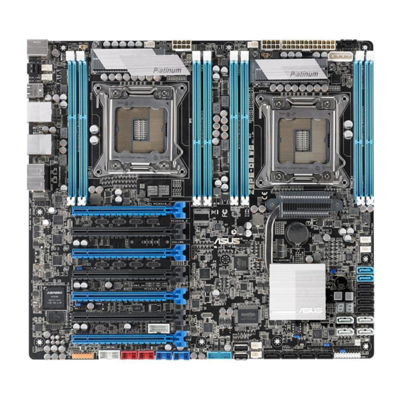
Page 27: Motherboard Layout
2.2.3 Motherboard layout Z9PE-D8 WS ASUS Z9PE-D8 WS... -
Page 28: Layout Contents
2.2.4 Layout contents Slots/Socket Page CPU sockets DDR3 sockets 2-13 PCI Express x8 / PCI Express x16 slots 2-16 Onboard Switches Page Power-on Switch 2-20 Reset Switch 2-20 Onboard LEDs Page DIMM Error LED (ERR_DIMM) 2-21 Baseboard Management Controller LED (BMC_LED1) 2-21 Q-Code LED (LED1_LED2) 2-22... - Page 29 Auxiliary panel connector (20-2 pin AUX_PANEL1) 2-38 Digital audio connector (4-1 pin SPDIF_OUT) 2-39 IEEE 1394a port connectors (10-1 pin IE1394_1/2) 2-39 VGA connector (VGA_HDR1) 2-40 Front panel audio connector (10-1 pin AAFP) 2-40 ASMB6 header (ASMB6) 2-41 ASUS Z9PE-D8 WS...
-
Page 30: Central Processing Unit (Cpu)
ASUS will shoulder the cost of repair only if the damage is shipment/transit-related. • Keep the cap after installing the motherboard. ASUS will process Return Merchandise Authorization (RMA) requests only if the motherboard comes with the cap on the LGA2011 socket. - Page 31 Press the right load lever with your thumb (C), then move it to the right (D) until it is released from the retention tab. Lift the load lever in the direction of the arrow (E). ASUS Z9PE-D8 WS...
- Page 32 Push the left load lever (F) to lift the load plate (G). Position the CPU over the socket, ensuring that the triangle mark is on the top-right corner of the socket. Triangle mark The CPU fits in only one correct orientation. DO NOT force the CPU into the socket to prevent bending the connectors on the socket and damaging the CPU! Remove the PnP cap (H) from the CPU socket and close the load plate (I).
- Page 33 (K). Insert the right load lever under the retention tab. 10. Push down the left load lever (L), and then insert the lever under the retention tab (M). ASUS Z9PE-D8 WS 2-11...
- Page 34 11. Apply some Thermal Interface Material to the exposed area of the CPU that the heatsink will be in contact with, ensuring that it is spread in an even thin layer. Some heatsinks come with pre- applied thermal paste. If so, skip this step.
-
Page 35: System Memory
DIMM_A1 DIMM_B1 DIMM_C1 DIMM_D1 1 DIMMs 2 DIMMs 4 DIMMs • *Refer to ASUS Server AVL for latest update. • Install the DIMMs starting from slot A1 (CPU1) and E1 (CPU2). • Always install DIMMs with the same CAS latency. For optimum compatibility, it is recommended that you obtain memory modules from the same vendor. - Page 36 2 CPU Configuration DIMM_A1 DIMM_B1 DIMM_C1 DIMM_D1 1 DIMMs 2 DIMMs 4 DIMMs 8 DIMMs 2 CPU Configuration DIMM_E1 DIMM_F1 DIMM_G1 DIMM_H1 1 DIMMs 2 DIMMs 4 DIMMs 8 DIMMs 2-14 Chapter 2: Hardware information...
-
Page 37: Installing A Dimm On A Single Clip Dimm Socket
Press the retaining clip outward to unlock the DIMM. Remove the DIMM from the socket. Support the DIMM lightly with your fingers when pressing the retaining clips. The DIMM might get damaged when it flips out with extra force. ASUS Z9PE-D8 WS 2-15... -
Page 38: Expansion Slots
Expansion slots In the future, you may need to install expansion cards. The following subsections describe the slots and the expansion cards that they support. Ensure to unplug the power cord before adding or removing expansion cards. Failure to do so may cause you physical injury and damage motherboard components. -
Page 39: Interrupt Assignments
ACPI Mode when used IRQ Holder for PCI Steering IRQ Holder for PCI Steering PS/2 Compatible Mouse Port Numeric Data Processor Primary IDE Channel Secondary IDE Channel * These IRQs are usually available for ISA or PCI devices. ASUS Z9PE-D8 WS 2-17... -
Page 40: Pci Express X16 Slot (X16 Link)
2.5.4 PCI Express x16 slot (x16 link) The onboard PCIE 1 and 3 provide one x16 Gen3 link to CPU1 (Auto switch to x8 link if PCIE 2 and 4 are occupied); The onboard PCIE 5 and 7 provide one x16 Gen3 link to CPU2. These slots support VGA cards and various server class high performance add-on cards. -
Page 41: Installing The Asmb6 Management Board
2.5.6 Installing the ASMB6 management board Follow the steps below to install an optional ASMB management board on your motherboard. Locate the ASMB6 header on the motherboard. Orient and press the ASMB6 management card in place ASUS Z9PE-D8 WS 2-19... -
Page 42: Onboard Switches
Onboard Switches Onboard switches allow you to fine-tune performance when working on a bare or open-case system. This is ideal for overclockers and gamers who continually change settings to enhance system performance. Power-on switch The motherboard comes with a power-on switch that allows you to power up or wake up the system. -
Page 43: Onboard Leds
Enabled only with ASMB6-i KVM on-board. Baseboard Management Controller LED (BMC_LED1) The BMC LED works with the ASUS ASMB6 management device and indicates its initiation status. When the PSU is plugged and the system is OFF, ASUS ASMB6 management device starts system initiation for about one (1) minute. -
Page 44: Q-Code Table
Q-Code LEDs The Q-Code LED design provides you the 2-digit display, allowing you to know the system status. Refer to the Q-code table below for details. Q-Code table Code Description Not used Power on. Reset type detection (soft/hard). AP initialization before microcode loading System Agent initialization before microcode loading PCH initialization before microcode loading Microcode loading... - Page 45 Reserved for future AMI progress codes Recovery PPI is not available Recovery capsule is not found Invalid recovery capsule FB – FF Reserved for future AMI error codes DXE Core is started NVRAM initialization Installation of the PCH Runtime Services ASUS Z9PE-D8 WS 2-23...
- Page 46 Q-Code table (continued) Code Description 63 – 67 CPU DXE initialization is started PCI host bridge initialization System Agent DXE initialization is started System Agent DXE SMM initialization is started 6B – 6F System Agent DXE initialization (System Agent module specific) PCH DXE initialization is started PCH DXE SMM initialization is started PCH devices initialization...
-
Page 47: Acpi/Asl Checkpoints
0x40 System is waking up from the S4 sleep state 0xAC System has transitioned into ACPI mode. Interrupt controller is in PIC mode. 0xAA System has transitioned into ACPI mode. Interrupt controller is in APIC mode. ASUS Z9PE-D8 WS 2-25... -
Page 48: Jumpers
Jumpers Clear RTC RAM (CLRTC1) This jumper allows you to clear the Real Time Clock (RTC) RAM in CMOS. You can clear the CMOS memory of date, time, and system setup parameters by erasing the CMOS RTC RAM data. The onboard button cell battery powers the RAM data in CMOS, which include system setup information such as system passwords. - Page 49 This jumper allows you to enable o disable the onboard VGA controller. Set to pins 1-2 to activate the VGA feature. SMBUS connection setting (TESLA_M_SW) SMBUS connection setting (TESLA_M_SW) This jumper allows you to select the connection to BMC or PCH for PCIE 1/3/5/7 SMBUS. ASUS Z9PE-D8 WS 2-27...
- Page 50 LSI MegaRAID or Intel RSTe selection jumper (3-pin RAID_SEL1) This jumper allows you to select the PCH SATA RAID mode to use LSI MegaRAID software or Intel Rapid Storage Technology enterprise 3.0 RAID. Place the ® jumper caps over pins 1–2 if you want to use the LSI MegaRAID software RAID Utility (default);...
-
Page 51: Connectors
Connectors 2.9.1 Rear panel connectors ASUS Z9PE-D8 WS 2-29... -
Page 52: Lan Port Led Indications
PS/2 mouse and keyboard port. This port is for a PS/2 mouse and keyboard. LAN 2 (RJ-45) port. This port allows Gigabit connection to a Local Area Network (LAN) through a network hub. Refer to the table below for the LAN port LED indications. -
Page 53: Internal Connectors
These connectors are for USB 2.0 ports. Connect the USB module cables to connectors USB78 and USB910, then install the modules to a slot opening at the back of the system chassis. These USB connectors comply with USB 2.0 specification that supports up to 480 Mbps connection speed. ASUS Z9PE-D8 WS 2-31... - Page 54 DO NOT forget to connect the fan cables to the fan connectors. Insufficient air flow inside the system may damage the motherboard components. • These are not jumpers! DO NOT place jumper caps on the fan connectors! • All fans feature the ASUS Fan Speed Control technology. 2-32 Chapter 2: Hardware information...
- Page 55 Serial port connectors (10-1 pin COM1/COM2) These connectors are for the serial (COM) ports. Connect the serial port module cable to one of these connectors, then install the module to a slot opening at the back of the system chassis. ASUS Z9PE-D8 WS 2-33...
- Page 56 Serial ATA 6.0/3.0 Gb/s connectors (7-pin SATA6G_1-2 [blue]; 7-pin SATA3G_3-6 [black]) These connectors connect to Serial ATA 6.0Gb/s or 3.0 Gb/s hard disk drives and optical disc drives via Serial ATA 6.0Gb/s or 3.0 Gb/s signal cables. 2-34 Chapter 2: Hardware information...
- Page 57 (7-pin SATA6G_E1/E2/E3/E4 [gray]) These connectors connect to Serial ATA 6.0 Gb/s hard disk drives via Serial ATA 6.0 Gb/s signal cables. • For high performance of ASUS SSD Caching, please connect one HDD and one SSD to Marvell SATA6G_E1/E2/E3/E4 connectors. ®...
- Page 58 Serial ATA SCU connectors (7-pin SATA_SCU1-4 [black]) These connectors connect to Serial ATA 3.0 Gb/s hard disk drives and optical disc drives via Serial ATA 3.0 Gb/s signal cables. 10. EATX power connectors (24-pin EATXPWR1, 8-pin EATX12V1/EATX12V2) These connectors are for an EATX power supply plugs. The power supply plugs are designed to fit these connectors in only one orientation.
-
Page 59: System Panel Connector
BIOS settings. Pressing the power switch for more than four seconds while the system is ON turns the system OFF. Reset button (2-pin RESET) This 2-pin connector is for the chassis-mounted reset button for system reboot without turning off the system power. ASUS Z9PE-D8 WS 2-37... - Page 60 12. Auxiliary panel connector (20-2 pin AUX_PANEL1) This connector is for additional front panel features including front panel SMB, locator LED and switch, chassis intrusion, and LAN LEDs. (1) Front panel SMB (6-1 pin FPSMB) These leads connect the front panel SMBus cable. (2) LAN activity LED (2-pin LAN12_LED) These leads are for Gigabit LAN activity LEDs on the front panel.
- Page 61 Never connect a USB cable to the IEEE 1394a connector. Doing so will damage the motherboard! The IEEE 1394a module is purchased separately. ASUS Z9PE-D8 WS 2-39...
- Page 62 15. VGA connector (VGA_HDR1) This connector supports the VGA High Dynamic-Range interface. 16. Front panel audio connector (10-1 pin AAFP) This connector is for a chassis-mounted front panel audio I/O module that supports either HD Audio or legacy AC`97 audio standard. Connect one end of the front panel audio I/O module cable to this connector.
- Page 63 17. ASMB6 header (ASMB6) This connector supports the ASUS Server Management Board 6 series. ASUS Z9PE-D8 WS 2-41...
- Page 64 2-42 Chapter 2: Hardware information...
-
Page 65: Chapter 3: Powering Up
This chapter describes the power up sequence, and ways of shutting down the system. Powering up Chapter 3:... - Page 66 Chapter summary Starting up for the first time ............3-3 Powering off the computer ............3-4 ASUS Z9PE-D8 WS...
-
Page 67: Starting Up For The First Time
Check the jumper settings and connections or call your retailer for assistance. At power on, hold down the <Del> key to enter the BIOS Setup. Follow the instructions in Chapter 4. ASUS Z9PE-D8 WS... -
Page 68: Powering Off The Computer
Powering off the computer 3.2.1 Using the OS shut down function If you are using Windows 2008 Server: ® Click the Start button, move the cursor to the triangle on the right of Log off, and then click Shut Down. From the Shutdown Event Tracker, select the option that best describes why you want to shut down the computer. -
Page 69: Chapter 4: Bios Setup
This chapter tells how to change the system settings through the BIOS Setup menus. Detailed descriptions of the BIOS parameters are also provided. BIOS setup Chapter 4:... - Page 70 Advanced menu ................. 4-15 Server Management menu ............4-41 Event Logs menu ............... 4-44 Boot menu .................. 4-47 Monitor menu ................4-50 4.10 Security menu ................4-52 4.11 Tool menu ................... 4-53 4.12 Exit menu ..................4-54 ASUS Z9PE-D8 WS...
-
Page 71: Managing And Updating Your Bios
USB flash disk drive when the BIOS file fails or gets corrupted. ASUS EZ Flash 2 : Allows you to update the BIOS using a USB flash disk. BUPDATER utility : Allows you to update the BIOS in DOS mode using a bootable USB flash disk drive. -
Page 72: Asus Ez Flash 2
4.1.2 ASUS EZ Flash 2 ASUS EZ Flash 2 feature allows you to update the BIOS without using a DOS-based utility. Before you start using this utility, download the latest BIOS from the ASUS website at www.asus.com. To update the BIOS using EZ Flash 2: Insert the USB flash disk that contains the latest BIOS file to the USB port. -
Page 73: Bupdater
Updating the BIOS file To update the BIOS file using BUPDATER : Visit the ASUS website at www.asus.com and download the latest BIOS file for the motherboard. Save the BIOS file to a bootable USB flash disk drive. Copy the BUPDATER utility (BUPDATER.exe) from the ASUS support website at support.asus.com to the bootable USB flash disk drive you created... - Page 74 The utility verifies the file, then starts updating the BIOS file. ASUSTek BIOS Update for DOS V1.06 (09/08/04) FLASH TYPE: MXIC 25L1605A Update ROM Current ROM BOARD: Z9PE-D8 WS BOARD: Z9PE-D8 WS VER: 0203 VER: 0206 DATE: 08/24/2011 DATE: 09/30/2011 PATH: WARNING! Do not turn off power during flash BIOS Note...
-
Page 75: Bios Setup Program
The BIOS setup screens shown in this section are for reference purposes only, and may not exactly match what you see on your screen. • Visit the ASUS website (www.asus.com) to download the latest BIOS file for this motherboard. ASUS Z9PE-D8 WS... -
Page 76: Bios Menu Screen
4.2.1 BIOS menu screen Menu items Menu bar Configuration fields General help Aptio Setup Utility - Copyright (C) 2011 American Megatrends, Inc. Main Ai Tweaker Advanced Server Mgmt Event Logs Boot Monitor Security Tool Exit Set the Date, Use Tab to BIOS Information switch between Data elements. -
Page 77: Menu Items
A scroll bar appears on the right side of a menu screen when there are items that do not fit on the screen. Press the Up/Down arrow keys or <Page Up> /<Page Down> keys to display the other items on the screen. ASUS Z9PE-D8 WS... -
Page 78: Main Menu
Main menu When you enter the BIOS Setup program, the Main menu screen appears. The Main menu provides you an overview of the basic system information, and allows you to set the system date, time, language, and security settings. The Server Management tab and menu appear only when you install ASMB card on the motherboard. -
Page 79: Ai Tweaker Menu
Set Ai Overclock Tuner to [Manual] to show BCLK Frequency. Use the <+> and <-> keys to adjust the value. You can also key in the desired value using the numeric keypad. The values range from 80.0MHz to 300.0MHz. ASUS Z9PE-D8 WS 4-11... - Page 80 CPU Ratio [Auto] This item allows users adjust the maximum non-turbo CPU ratio. Use the <+> and <-> keys to adjust the value. The values range from 12 to 57 with 1 interval. The values range from 12 to 57 with 1 interval. CPU1 Voltage [Auto] Use the <+>...
-
Page 81: Dram Timing Control
The values range from 4 to 15 with 1 interval. DRAM RAS# PRE Time [Auto] Use the <+> and <-> keys to adjust the value. The values range from 4 to 15 The values range from 4 to 15 with 1 interval. ASUS Z9PE-D8 WS 4-13... - Page 82 DRAM RAS# ACT Time [Auto] Use the <+> and <-> keys to adjust the value. The values range from 4 to 40 The values range from 4 to 40 with 1 interval. DRAM COMMAND Mode [Auto] Use the <+> and <-> keys to adjust the value. The values range from 1 to 3 The values range from 1 to 3 with 1 interval.
-
Page 83: Advanced Menu
F2: Previous Values DCU Streamer Prefetcher [Enabled] F5: Optimized Defaults DCU IP Pretetcher [Enabled] F10: Save & Exit Intel Virtualization Technology [Enabled] ESC: Exit Local APIC Mode [Auto] Version 2.14.1219. Copyright (C) 2011 American Megatrends, Inc. ASUS Z9PE-D8 WS 4-15... -
Page 84: Socket 1 Cpu Information
Socket 1 CPU Information Enter to view socket specific CPU Information. Aptio Setup Utility - Copyright (C) 2011 American Megatrends, Inc. Advanced Socket 1 CPU Information Intel(R) Xeon(R) CPU E5-2660 0 @ 2.20GHz CPU Signature 206d6 Microcode Patch Max CPU Speed 2200 MHz Min CPU Speed 1200 MHz... - Page 85 This item allows you to enable/disable prefetching of next L1 data line based upon multiple loads in same cache line. Configuration options: [Disabled] [Enabled] DCU IP Prefetcher [Enabled] This item allows you to enable/disable prefetching of next L1 line based upon sequential load history. Configuration options: [Disabled] [Enabled] ASUS Z9PE-D8 WS 4-17...
-
Page 86: Cpu Power Management Configuration
Intel Virtualization Technology [Enabled] When this item is enabled, VMM can utilize the additional hardware capabilities provided by Vanderpool Technology. Configuration options: [Disabled] [Enabled] Local APIC Mode [Auto] Allows you to enable one or both the Advanced Programmable Interrupt Controllers (APIC) with APIC ID values greater than 254. -
Page 87: Long Duration Power Limit
<+> and <-> keys to adjust the value. Recommended short duration power1 1.2 * Long Duration Short Duration Power Limit Allows you to set short duration power limit in watts. Use the <+> and <-> keys to adjust the value. ASUS Z9PE-D8 WS 4-19... -
Page 88: Chipset Configuration
4.5.3 Chipset Configuration Aptio Setup Utility - Copyright (C) 2011 American Megatrends, Inc. Advanced QPI Configuration Page QPI Configuration Memory Configuration CPU II0 Bridge Configuration PCH Configuration Intel(R) VT for Directed I/O Configuration QPI Configuration Aptio Setup Utility - Copyright (C) 2011 American Megatrends, Inc. Advanced Enable/Disable Isoc Current QPI Link Speed... -
Page 89: Memory Configuration
DDR3 1333] [Force DDR3 1600] [Force DDR3 1866] [Force DDR3 2133] [Force DDR3 2400] [Force DDR3 2666] Channel Interleaving [Auto] Select different channel interleaving setting. Configuration options: [Auto] [1 Way] [2 Way] [3 Way] [4 Way] ASUS Z9PE-D8 WS 4-21... - Page 90 Rank Interleaving [Auto] Select different rank interleaving setting. Configuration options: [Auto] [1 Way] [2 Way] [4 Way] [8 Way] Patrol Scrub [Disabled] This item allows you to enable/disable Patrol Scrub. Configuration options: [Disabled] [Enabled] Demand Scrub [Enabled] This item allows you to enable/disable Demand Scrubbing Feature. Configuration options: [Enabled] [Disabled] Data Scrambling [Enabled] This item allows you to enable/disable Data Scrambling.
- Page 91 Version 2.14.1219. Copyright (C) 2011 American Megatrends, Inc. Intel(R) I/OAT [Disabled] This item allows you to enable/disable Intel I/O accelaration technology. Configuration options: [Disabled] [Enabled] DCA Support [Enabled] This item allows you to enable/disable direct cache access support. Configuration options: [Disabled] [Enabled] ASUS Z9PE-D8 WS 4-23...
-
Page 92: Pch Configuration
VGA Priority [offboard] This item allows you to decide the priority between onboard and 1st offboard video device found. Configuration options: [Onboard] [Offboard] PCH Configuration Aptio Setup Utility - Copyright (C) 2011 American Megatrends, Inc. Advanced Support for PCH Compatibility Name Patsburg Revision ID(CRID) - Page 93 Coherency Support [Disabled] This item allows you to enable/disable VT-d Engine Coherency support. Configuration options: [Disabled] [Enabled] ATS Support [Disabled] This item allows you to enable/disable VT-d Engine address translation services (ATS) support. Configuration options: [Disabled] [Enabled] ASUS Z9PE-D8 WS 4-25...
-
Page 94: Pch Sata Configuration
SATA Port1 ST3500320AS(500GB) (3)RAID Mode. SATA Port2 Not Present SATA Port3 Not Present SATA Port4 Not Present SATA Port5 ASUS DRW ATAPI SATA Port6 Not Present SATA Mode [AHCI Mode] S.M.A.R.T. Status Check [Enabled] Aggressive Link Power Management[Enabled] Port1 Staggered Spin-up... -
Page 95: Pch Scu Configuration
Not Present →←: Select Screen Select Item ↑↓: Enter: Select Item +/-: Change Opt. F1: General Help F2: Previous Values F5: Optimized Defaults F10: Save & Exit ESC: Exit Version 2.14.1219. Copyright (C) 2011 American Megatrends, Inc. ASUS Z9PE-D8 WS 4-27... -
Page 96: Pci Subsystem Settings
4.5.6 PCI Subsystem Settings Aptio Setup Utility - Copyright (C) 2011 American Megatrends, Inc. Advanced In case of multiple Option PCI Bus Driver Version V 2.05.00 ROMs (Legacy and EFI Compatible), specifies what PCI Option ROM Handling PCI option ROM to lanuch. PCI ROM Priority [EFI Compatible ROM] PCI Common Settings... -
Page 97: Pci Express Settings
Version 2.14.1219. Copyright (C) 2011 American Megatrends, Inc. ASPM Support [Disabled] This item allows you to set the ASPM level. Configuration options: [Disabled] [Auto] [Force L0s] [Force L0s] Force all links to L0s state. [Auto] BIOS auto configure. [Disabled] Disabled ASPM. ASUS Z9PE-D8 WS 4-29... - Page 98 PCIE Slot Option ROM Configuration Aptio Setup Utility - Copyright (C) 2011 American Megatrends, Inc. Advanced Enable or Disable Boot Option Legacy OpROM Support for Legacy Mass Storage Launch Storage OpROM [Enabled] Devices with Option ROM. PCIE1 Option Rom [Enabled] PCIE2 Option Rom [Enabled] PCIE3 Option Rom...
-
Page 99: Usb Configuration
This item sets the time-out value for control, bulk, and interrupt transfer. Configuration options: [1 sec] [5 sec] [10 sec] [20 sec] Device reset time-out [20 sec] USB mass storage device Start Unit command time-out. Configuration options: [10 sec] [20 sec] [30 sec] [40 sec] ASUS Z9PE-D8 WS 4-31... - Page 100 Device power-up delay [Auto] This item sets the maximum time the device will take before it properly reports itself to the Host Controller. ‘Auto’ uses default values: for a Root port, it is 100ms; for a Hub port, the delay is taken from Hub descriptor. Configuration options: [Manual] [Auto] Device power-up delay in seconds [X] This item appears only when you set the Device power-up delay item to...
-
Page 101: Acpi Settings
Aptio Setup Utility - Copyright (C) 2011 American Megatrends, Inc. Advanced Enable or disable Windows WHEA Support [Enabled] Hardware Error Architecture. WHEA Support [Enabled] Allows you to enable or disable the Windows Hardware Error Architecture support. Configuration options: [Disabled] [Enabled] ASUS Z9PE-D8 WS 4-33... -
Page 102: Apm Setting
4.5.10 APM setting Aptio Setup Utility - Copyright (C) 2011 American Megatrends, Inc. Advanced Specify what state to go to Restrore AC Power Loss [Last State] when power is re-applied after Power On By PS/2 Keyboard [Disabled] a power failure (G3 state). Power On By PS/2 Mouse [Disabled] Power On By PCIE... -
Page 103: Serial Port Console Redirection
Extended ASCII char set Bits per second [57600] Selects serial port transmission speed. The speed must be matched on the other side. Long or noisy lines may require lower speeds. Configuration options: [9600] [19200] [38400] [57600] [115200] ASUS Z9PE-D8 WS 4-35... -
Page 104: Console Redirection Settings
Data Bits [8] Configuration options: [7] [8] Parity [None] A parity bit can be sent with the data bits to detect some transmission errors. [Mark] and [Space] parity do not allow for error detection. [None] No parity bit [Even] Parity bit is 0 if the num of 1’s in the data bits is even [Odd] Parity bit is 0 if num of 1’s in the data bits is odd [Mark]... -
Page 105: Onboard Lan Configuration
INTEL W82574L OpROM1 [PXE] INTEL W82574L OpROM2 [PXE] INTEL W82574L OpROM1 [PXE] This item launched INTEL W82574L OpROM1. Configuration options: [Disabled] [PXE] [iSCSI] INTEL W82574L OpROM2 [PXE] This item launched INTEL W82574L OpROM2. Configuration options: [Disabled] [PXE] [iSCSI] ASUS Z9PE-D8 WS 4-37... -
Page 106: Marvell Sata Configuration
4.5.13 Mar�ell SATA Configuration Aptio Setup Utility - Copyright (C) 2011 American Megatrends, Inc. Advanced Marvell SATA Configuration Marvell Storage Controller [Enabled] Marvell Storage OPROM [Enabled] Marvell Storage Controller [Enabled] Configuration options: [Disabled] [Enabled] Marvell Storage OPROM [Enabled] Configuration options: [Disabled] [Enabled] 4-38 Chapter 4: BIOS setup... -
Page 107: Onboard Devices Configuration
This item allows you to enable or disable Asmedia USB 3.0. Configuration options: [Disabled] [Enabled] Asmedia USB 3.0 Battery Charging S [Enabled] This item allows you to enable or disable Asmedia USB 3.0 Battery Charging Configuration options: [Disabled] [Enabled] ASUS Z9PE-D8 WS 4-39... -
Page 108: Runtime Error Logging
4.5.15 Runtime Error Logging Aptio Setup Utility - Copyright (C) 2011 American Megatrends, Inc. Advanced Runtime Error Logging Support [Disabled] Runtime Error Logging Support [Disabled] This item allows you to enable or disable Runtime Error Logging Support. Configuration options: [Disabled] [Enabled] The following item appears only when you set Runtime Error Logging Support to [Enabled]. -
Page 109: Server Management Menu
O/S Wtd Timer Policy [Reset] Allows to configure how the system should respond if the OS Boot Watchdog Timer expires. Not available if O/S Boot Watchdog Timer is disabled. Configuration options: [Do Nothing] [Reset] [Power Down] ASUS Z9PE-D8 WS 4-41... -
Page 110: System Event Log
4.6.1 System Event Log Aptio Setup Utility - Copyright (C) 2011 American Megatrends, Inc. Server Mgmt Change this to enable or Enabling/Disabling Options disable all features of SEL Components [Disabled] system Event Logging during boot. Erasing Settings Erase SEL [No] When SEL is Full [Do Nothing] Note: All values changed here do not take effect... -
Page 111: Bmc Network Configuration
The following items appears only when you set Configuration Address source to [Static Mode]. Station IP address [0.0.0.0] Allows to input Station IP address. Subnet mask [0.0.0.0] Allows to input Subnet mask. Gateway IP address [0.0.0.0] Allows to input Gateway IP address. ASUS Z9PE-D8 WS 4-43... -
Page 112: Event Logs Menu
Event Logs menu The Event Logs allows you to change or view the event log settings. The Event Logs menu appears when the ASMB card is not installed on the motherboard. Aptio Setup Utility - Copyright (C) 2011 American Megatrends, Inc. Event Logs Press <Enter>... -
Page 113: Change Smbios Event Log Settings
This item allows you to choose options for reactions to a full Smbios Event Log. Configuration options: [Do Nothing] [Erase Immediately] Smbios Event Log Standard Settings Log System Boot Event [Disabled] This item allows you to choose options to enable/disable logging of System boot event. Configuration options: [Enabled] [Disabled] ASUS Z9PE-D8 WS 4-45... - Page 114 MECI [1] This item allows you to set Mutiple Event Count Increment (MECI). The number of occurrences of a duplicate event that must pass before the multiplt-event counter associated with the log entry is updated, specified as a numeric value in the range 1 to 255.
-
Page 115: Boot Menu
This item allows you to enable or disable the full screen logo display feature. Configuration options: [Disabled] [Enabled] 1. Set Full Screen Logo to [Enabled] to use the ASUS MyLogo2™ feature. 2. Set Full Screen Logo to [Disabled] to select the desired Post Report waiting time from 1~10 sec. -
Page 116: Boot Option Priorities
The number of device items that appears on the screen depends on the number of devices installed in the system. • To select the boot device during system startup, press <F8> when ASUS Logo appears. • To access Windows OS in Safe Mode, please press <F8> after POST. -
Page 117: Boot Override
The number of device items that appears on the screen depends on the number of devices installed in the system. Select [Disabled] to disallow this function. • To select the boot device during system startup, press <F8> when ASUS Logo appears. •... -
Page 118: Monitor Menu
Monitor menu The Monitor menu displays the system temperature/power status, and allows you to change the fan settings. Aptio Setup Utility - Copyright (C) 2011 American Megatrends, Inc. Main Ai Tweaker Advanced Server Mgmt Event Logs Boot Monitor Security Tool Exit CPU1 Temperature 90.0ºC/194.0ºF CPU2 Temperature... - Page 119 FAN Speed Control [Generic Mode] This item allows you to configure the ASUS Smart Fan feature that smartly adjusts the fan speeds for more efficient system operation. Configuration options: [Generic Mode] [High Speed Mode] [Full Speed Mode]...
-
Page 120: 4.10 Security Menu
4.10 Security menu The Security menu items allow you to change the system security settings. Aptio Setup Utility - Copyright (C) 2011 American Megatrends, Inc. Main Ai Tweaker Advanced Server Mgmt Event Logs Boot Monitor Security Tool Exit Set Setup Administrator Password Description Password If ONLY the Administrator's password is set,... -
Page 121: 4.11 Tool Menu
Be used to update BIOS ASUS EZ Flash 2 Utility ASUS EZ Flash 2 Utility This item allows you to run ASUS EZ Flash BIOS ROM Utility when you press <Enter>. Check section 4.1.2 ASUS EZ Flash 2 Utility for details. ASUS Z9PE-D8 WS... -
Page 122: 4.12 Exit Menu
4.12 Exit menu The Exit menu items allow you to save or discard your changes to the BIOS items. Aptio Setup Utility - Copyright (C) 2011 American Megatrends, Inc. Main Ai Tweaker Advanced Server Mgmt Event Logs Boot Monitor Security Tool Exit Discard Changes &... - Page 123 This chapter provides instructions for setting up, creating, and configuring RAID sets using the available utilities. RAID configuration...
- Page 124 Setting up RAID ................5-3 LSI Software RAID Configuration Utility ........5-5 Intel Rapid Storage Technology enterprise SCU/SATA ® Option ROM Utility ..............5-25 Intel Rapid Storage Technology enterprise Utility ® (Windows) ................... 5-35 Marvell RAID utility ..............5-41 ASUS Z9PE-D8 WS...
-
Page 125: Setting Up Raid
• Please refer to chapter 2 for how to select the RAID configuration utility. Move the jumper to choose between LSI MegaRAID and Intel ® Rapid RAID. ASUS Z9PE-D8 WS... -
Page 126: Installing Hard Disk Drives
5.1.2 Installing hard disk drives The motherboard supports Serial ATA for RAID set configuration. For optimal performance, install identical drives of the same model and capacity when creating a disk array. To install the SATA hard disks for RAID configuration: Install the SATA hard disks into the drive bays following the instructions in the system user guide. -
Page 127: Lsi Software Raid Configuration Utility
LSI Software RAID Configuration Utility Ver C.05 Sep 17, 2010 BIOS Version A.10.09231523R Management Menu Configure Initialize Objects Rebuild Check Consistency Configure VD(s) Use Cursor Keys to Navigate Between Items And Press Enter To Select An Option ASUS Z9PE-D8 WS... -
Page 128: Creating A Raid Set
Menu Description Configure Allows you to create RAID 0, RAID 1 or RAID 10 set using the Easy Configuration or the New Configuration command. This menu also allows you to view, add, or clear RAID configurations or select the boot drive Initialize Allows you to initialize the virtual drives of a created RAID set Objects... - Page 129 LSI Software RAID Configuration Utility Ver C.05 Sep 17, 2010 BIOS Version A.10.09231523R Easy Configuration - ARRAY SELECTION MENU Select Configurable Array(s) Management Menu PORT # Configure DNLIN A00-00 SPAN-1 Initialize Objects DNLIN A00-01 Rebuild Check Consistency Cursor Keys, SPACE-(De)Select F2-ChIdInfo F3-SlotInfo F10-Configure Esc-Quit ASUS Z9PE-D8 WS...
- Page 130 Press <F10> again, the virtual drive information appears including a Virtual Drive menu that allows you to change the virtual drive parameters. LSI Software RAID Configuration Utility Ver C.05 Sep 17, 2010 BIOS Version A.10.09231523R Virtual Drive(s) Configured RAID Size #Stripes StripSz Status...
- Page 131 Accept SPAN = NO Disk Write Cache Setting Of VD Use Cursor Keys To Navigate Between Items And Press Enter To Select An Option Enabling DWC can improve the performance, but with the risk of data loss. ASUS Z9PE-D8 WS...
- Page 132 12. When finished setting the selected virtual drive configuration, select Accept from the menu, and then press <Enter>. LSI Software RAID Configuration Utility Ver C.05 Sep 17, 2010 BIOS Version A.10.09231523R Virtual Drive(s) Configured RAID Size #Stripes StripSz Status Easy Configuration - ARRAY SELECTION MENU Management Menu 148.580GB 64 KB...
- Page 133 SPAN = NO Enter VD Size: Use Cursor Keys to Navigate Between Items And Press Enter To Select An Option Follow step 10 to 14 of the previous section: Using Easy Configuration to create the RAID set. ASUS Z9PE-D8 WS 5-11...
-
Page 134: Adding Or Viewing A Raid Configuration
5.2.2 Adding or �iewing a RAID configuration You can add a new RAID configuration or view an existing configuration using the �iew/Add Configuration command. Adding a new RAID configuration To add a new RAID configuration: From the Management Menu, select Configure > �iew/Add Configuration, and then press <Enter>. -
Page 135: Initializing The Virtual Drives
LSI Software RAID Configuration Utility Ver C.05 Sep 17, 2010 BIOS Version A.10.09231523R Virtual Drive(s) Configured Management Menu RAID Size #Stripes StripSz Status Configure Initialize 148.580GB 64 KB ONLINE Objects Rebuild Check Consistency Virtual Drives Virtual Drive 0 Select VD SPACE-(De)Select, F10-Initialize ASUS Z9PE-D8 WS 5-13... - Page 136 Press <F10> to start initialization. When prompted, select Yes from the Initialize? dialog box, and then press <Enter>. LSI Software RAID Configuration Utility Ver C.05 Sep 17, 2010 BIOS Version A.10.09231523R Virtual Drive(s) Configured Management Menu RAID Size #Stripes StripSz Status Configure Initialize...
-
Page 137: Using The Objects Command
LSI Software RAID Configuration Utility Ver C.05 Sep 17, 2010 BIOS Version A.10.09231523R Vitual Drive(1) Virtual Drive 0 Objects Management Menu Adapter Configure Virtual Drive Initialize Physical Drive Objects Rebuild Check Consistency Select VD Press ENTER To Select A VD, <Del> To Delete A VD ASUS Z9PE-D8 WS 5-15... - Page 138 Select Initialize from the pop-up menu, and then press <Enter> to start initialization. LSI Software RAID Configuration Utility Ver C.05 Sep 17, 2010 BIOS Version A.10.09231523R Vitual Drive(1) Virtual Drive 0 Objects Management Menu Adapter Configure Virtual Drive Initialize Physical Drive Objects Vitual Drive(0) Rebuild...
-
Page 139: Rebuilding Failed Drives
LSI Software RAID Configuration Utility Ver C.05 Sep 17, 2010 BIOS Version A.10.09231523R REBUILD - PHYSICAL DRIVES SELECTION MENU Management Menu PORT # Configure ONLIN A00-00 Initialize Objects FAIL A00-01 Rebuild Check Consistency Port # 1 DISK 77247MB HDS728080PLA380 PF20A60A SPACE-(De)Select,F10-Start Rebuild,F2-Drive Information,F3-View Virtual Drives ASUS Z9PE-D8 WS 5-17... - Page 140 After selecting the drive to rebuild, press <F10>. When prompted, press <Y> to rebuild the drive. LSI Software RAID Configuration Utility Ver C.05 Sep 17, 2010 BIOS Version A.10.09231523R REBUILD - PHYSICAL DRIVES SELECTION MENU Management Menu PORT # Configure ONLIN A00-00 Initialize Objects...
-
Page 141: Checking The Drives For Data Consistency
LSI Software RAID Configuration Utility Ver C.05 Sep 17, 2010 BIOS Version A.10.09231523R Virtual Drive(s) Configured Management Menu RAID Size #Stripes StripSz Status Configure Initialize 148.580GB 64 KB ONLINE Objects Rebuild Check Consistency Virtual Drives Virtual Drive 0 Select VD SPACE-(De)Select, F10-Check Consistency ASUS Z9PE-D8 WS 5-19... - Page 142 When prompted, use the arrow keys to select Yes from the Consistency Check? dialog box, and then press <Enter>. LSI Software RAID Configuration Utility Ver C.05 Sep 17, 2010 BIOS Version A.10.09231523R Virtual Drive(s) Configured Management Menu RAID Size #Stripes StripSz Status Configure...
- Page 143 Select Check Consistency from the pop-up menu, and then press <Enter>. When prompted, use the arrow keys to select Yes from the dialog box to check the drive. When checking is complete, press any key to continue. ASUS Z9PE-D8 WS 5-21...
-
Page 144: Deleting A Raid Configuration
5.2.6 Deleting a RAID configuration To delete a RAID configuration From the Management Menu, select Configure > Clear Configuration, and then press <Enter>. LSI Software RAID Configuration Utility Ver C.05 Sep 17, 2010 BIOS Version A.10.09231523R Configuration Menu Easy Configuration New Configuration Management Menu Configure... -
Page 145: Selecting The Boot Drive From A Raid Set
Select Boot Drive Objects Rebuild Check Consistency Select A Boot VD Use Cursor Keys To Navigate Between Items And Press Enter To Select An Option The virtual drive is selected as boot drive. Press any key to continue. ASUS Z9PE-D8 WS 5-23... -
Page 146: Enabling Writecache
5.2.8 Enabling WriteCache You may manually enable the RAID controller’s WriteCache option after creating a RAID set to improve the data transmission performance. When you enable WriteCache, you may lose data when a power interruption occurs while transmitting or exchanging data among the drives. The WriteCache function is recommended for RAID 1 and RAID 10 sets. -
Page 147: Intel ® Rapid Storage Technology Enterprise Scu/Sata Option Rom Utility
Turning on the system. During POST, press <Del> to enter BIOS. Go to Advanced Menu > PCH SCU SATA Configuration, then press <Enter>. Confirm all the SATA hard disk drives you installed are correctly displayed, then reboot system. During POST, press <Ctrl+I> to display the utility main menu. ASUS Z9PE-D8 WS 5-25... - Page 148 To enter the Intel Rapid Storage Technology enterprise SCU Option ROM utility: ® Install all the Serial ATA hard disk drives. Turn on the system. During POST, press <Ctrl+I> to display the utility main menu. Intel(R) Rapid Storage Technology enterprise - SATA Option ROM - 3.0.0.1104 Copyright(C) 2003-11 Intel Corporation.
-
Page 149: Creating A Raid Set
Select 2 to 6 disks to use in creating the volume. [ ↑↓ ]-Prev/Next [SPACE]-SelectDisk [ENTER]-Done Use the up/down arrow key to select a drive, and then press <Space> to select. A small triangle marks the selected drive. Press <Enter> after completing your selection. ASUS Z9PE-D8 WS 5-27... -
Page 150: Creating A Recovery Set
Use the up/down arrow keys to select the stripe size for the RAID array (for RAID 0, 10 and 5 only), and then press <Enter>. The available stripe size values range from 4 KB to 128 KB. The following are typical values: RAID 0: 128KB RAID 10: 64KB RAID 5: 64KB... - Page 151 Press <Y> to create the recovery set and return to the main menu, or <N> to go back to the CREATE VOLUME menu. If a recovery set is created, you cannot add more RAID sets even when you have more non-RAID disks installed in your system. ASUS Z9PE-D8 WS 5-29...
-
Page 152: Deleting A Raid Set
5.3.3 Deleting a RAID set Take caution when deleting a RAID set. You will lose all data on the hard disk drives when you delete a RAID set. To delete a RAID set: From the utility main menu, select 2. Delete RAID Volume and press <Enter>. -
Page 153: Resetting Disks To Non-Raid
From the utility main menu, select 4. Exit, and then press <Enter>. The following warning message appears. CONFIRM EXIT Are you sure you want to exit? (Y/N): Press <Y> to exit or press <N> to return to the utility main menu. ASUS Z9PE-D8 WS 5-31... -
Page 154: Rebuilding The Raid
5.3.6 Rebuilding the RAID This option is only for the RAID 1 set. Rebuilding the RAID with other non-RAID disk If any of the SATA hard disk drives included in the RAID 1 array failed, the system displays the status of the RAID volume as “Degraded” during POST. You can rebuild the RAID array with other installed non-RAID disks. -
Page 155: Rebuilding The Raid With A New Hard Disk
SATA Port. Select a destination disk with the same size as the original hard disk. Reboot the system and then follow the steps in section Rebuilding the RAID with other non-RAID disk. ASUS Z9PE-D8 WS 5-33... -
Page 156: Setting The Boot Array In The Bios Setup Utility
5.3.7 Setting the Boot array in the BIOS Setup Utility You can set the boot priority sequence in the BIOS for your RAID arrays when creating multi-RAID using the Intel Rapid Storage Technology. ® To set the boot array in the BIOS: Set at least one of the arrays bootable to boot from the hard disk. -
Page 157: Intel ® Rapid Storage Technology Enterprise Utility (Windows)
Your storage system is configured for data protection, increased performance and optimal data storage capacity. You can further optimize your storage system by creating additional volumes. You can click Rescan to re-scan any attached hard disks. ASUS Z9PE-D8 WS 5-35... -
Page 158: Creating A Raid Set
5.4.1 Creating a RAID set To create a RAID set From the utility main menu, select Create Volume and select volume type. Then click Next. Enter a name for the RAID set, then select the array disks. Select Volume Size tab, you can drag the bar to decide the volume size. Then click Next. - Page 159 You still need to partition your new volume using Windows Disk Management before adding any data. When you are finished, you will see the following screen in Volumes field and you can change related items in the Volume Properties field. ASUS Z9PE-D8 WS 5-37...
-
Page 160: Change Volume Type
5.4.2 Change Volume Type When you are finished to create a RAID set, you can view or change related items in the Volume Properties field. According to the following steps to change the type in Volume Properties: Click the SAS array items you want to change in Volumes field. From the Volume Properties field, select Type:RAID 1 Change type. -
Page 161: Delete Volume
Volumes field you want to delete. Then select Delete volume in Volume Properties field. The following screen appears. Click Yes to delete the volume and return to the utility main menu, or click No to return to the main menu. ASUS Z9PE-D8 WS 5-39... -
Page 162: Preferences
5.4.4 Preferences System Preferences Allow you set to show the notification area icon and show system information, warning, or errors here. E-Mail Preferences Allow you set to sent e-mail of the following events: Storage system information Storage system warnings Storage system errors 5-40 Chapter 5: RAID configuration... -
Page 163: Marvell Raid Utility
Press <Space> to select the hard drives to be included in the RAID array. An asterisk (*) appears in front of the selected hard drive. After selecting all the drives needed for the RAID array, press <Enter> to continue. ASUS Z9PE-D8 WS 5-41... - Page 164 Marvell BIOS Setup (c) 2011 Marvell Technology Group Ltd. Configure->Select free disksCreate Virtual Disk HBA 0: Marvell 0 RAID Level : RAID 0 Virtual Disks ├ Max Size(MB) : 305253 Free Physical Disks └ Stripe Size : 64KB ├ PD 0: ST3160812AS Gigabyte Rounding : 1G └...
-
Page 165: Delete An Existing Raid Array
Stripte Size │ └ PD 8: ST3160812AS RAID Mode RAID0 │ Free Physical Disks Size 304128MB └ BGA Status Number of PDs Members ▶ ▶ Help Delete the selected virtual disk. ENTER: Operation F10: Exit/Save ESC: Return ASUS Z9PE-D8 WS 5-43... - Page 166 The following warning message appears: Delete Virtual Disk Do you want to delete this virtual disk ? Press <Y> to delete the selected RAID array. The following warning message appears: Delete MBR Do you want to delete MBR from this virtual disk ? Press <Y>...
-
Page 167: Chapter 6: Driver Installation
This chapter provides the instructions for installing the necessary drivers for different system components. Driver Chapter 6: installation... - Page 168 Marvell Storage Utility installation ........... 6-26 Asmedia ASM104x USB 3.0 Host Controller Driver installation .................. 6-30 6.10 Intel WG82574L Gigabit Adapters Driver installation .... 6-33 ® 6.11 VGA driver installation............... 6-36 6.12 Management applications and utilities installation ....6-39 ASUS Z9PE-D8 WS...
-
Page 169: Raid Driver Installation
<Enter> to enter the sub-menu. C60x INTEL RAID Driver C600 INTEL RAID Driver Windows 32 bit (AHCI / AHCI RAID) Windows 64 bit (AHCI / AHCI RAID) Windows 32 bit (SCU RAID) Windows 64 bit (SCU RAID) Back Exit ASUS Z9PE-D8 WS... - Page 170 LSI 2008 SAS2 Driver LSI 2008 SAS2 Driver Windows XP 32 bit Windows XP 64 bit Windows Server 2003 32 bit Windows Server 2003 64 bit Windows Vista 32 bit Windows Vista 64 bit Windows Server 2008 32 bit Windows Server 2008 64 bit Windows 7 32 bit Windows 7 64 bit Windows Server 2008 R2 64 bit...
-
Page 171: Installing The Raid Controller Driver
® Boot the computer using the Windows Server 2008 OS installation disc. ® Follow the screen instructions to start installing Windows Server 2008. When prompted to choose a type of installation, click Custom (advanced). Click Load Driver. ASUS Z9PE-D8 WS... - Page 172 A message appears, reminding you to insert the installation media containing the driver of the RAID controller driver. If you have only one optical drive installed in your system, eject the Windows OS installation disc and replace with the motherboard Support DVD into the optical drive. Click Browse to continue.
- Page 173 Enterprise RAID driver disk to the USB floppy disk drive, ® select OK, then press <Enter>. Insert Driver Disk Insert your driver disk into /dev/fd0 and press “OK” to continue. Back The drivers for the RAID card are installed to the system. ASUS Z9PE-D8 WS...
- Page 174 When asked if you will load additional RAID controller drivers, select No, then press <Enter>. More Driver Disks? Do you wish to load any more driver disks? Follow the onscreen instructions to finish the OS installation. When the installation is completed, DO NOT click Reboot. Press <Ctrl> + <Alt>...
- Page 175 Enter the following command at the boot: Linux dd blacklist=isci blacklist=ahci nodmraid, then press <ENTER>. Select Yes using the <Tab> key when asked if you have the driver disk, then press <Enter>. Main Menu Do you have a driver disk? ASUS Z9PE-D8 WS...
- Page 176 You have multiple devices which could serve as source for a driver disk. Choose one you like to use and select OK, then press <Enter>. Driver Disk Source You have multiple devices which could serve as source for a driver disk. Which would you like to use? Cancel Insert the Red Hat...
- Page 177 -o loop [image file name] image Example: mount -o loop megasr-15-15.00.0120.2012-1-sles11- ga-x86__64.img image Copy the contents of the image directory, labeled as 01, into a FAT32 USB drive. Rename the 01 folder to CD Image. ASUS Z9PE-D8 WS 6-11...
- Page 178 Installing SUSE 11 Linux OS To install the LSI MegaRAID controller driver when installing SUSE Linux Enterprise Server OS: Boot the system from the SUSE OS installation CD. Use the arrow keys to select Installation from the Boot Options menu. Press <F6>, then select Yes from the menu.
- Page 179 When below screen appears, select the USB floppy disk drive (sda) as the driver update medium. Select OK, then press <Enter>. Please choose the Driver Update medium. sda: USB Floppy other device Back Select Back and follow the onscreen instructions to finish the installation. ASUS Z9PE-D8 WS 6-13...
-
Page 180: Intel ® Chipset Device Software Installation
® Intel Chipset Device Software installation This section provides the instructions on how to install the Intel chipset device ® software on the system. You need to manually install the Intel ® chipset device software on a Windows operating system. To install the Intel chipset device software: ®... - Page 181 Select Yes to accept the terms of the License Agreement and continue the process. Read the Readme File Information and press Next to continue the installation. Toggle Yes, I want to restart the computer npw and click Finish to complete the setup process. ASUS Z9PE-D8 WS 6-15...
-
Page 182: Intel Network Connections Software Installation
Intel Network Connections Software installation This section provides the instructions on how to install the Intel ® Network Connections Software on the system. You need to manually install the Intel Network Connections Software on a ® Windows operating system. To install the Intel Network Connections Software: ®... - Page 183 Click Next when the Intel(R) Network Connections–InstallShield Wizard window appears. Toggle I accept the terms in the license agreement and click Next to continue. Click the Intel(R) PROSet for Windows Device Manager box, and then click Next to start the installation. ASUS Z9PE-D8 WS 6-17...
- Page 184 Follow the screen instructions to complete installation. When finished, press Finish to continue. 6-18 Chapter 6: Driver installation...
-
Page 185: Audio Driver Installation
Audio driver installation This section provides the instructions on how to install the ASUS MIO Audio card/ Realtek High Definition Audio driver. You need to manually install the ASUS MIO Audio card/ Realtek High Definition Audio driver on a Windows operating system. - Page 186 When the installation completes, click Yes, I want to restart my computer now to restart your computer before using the program. 6-20 Chapter 6: Driver installation...
-
Page 187: Intel ® C600 Series Chipset Scu Sata Raid Drivers Installation
DVD to locate the file ASSETUP.EXE from the BIN folder. Double-click the ASSETUP.EXE to run the support DVD. Click the item Intel C600 Series Chipset SCU SATA RAID Drivers from the ® menu, and then follow the onscreen instructions to complete the installation. ASUS Z9PE-D8 WS 6-21... -
Page 188: Marvell Magni Installation
Marvell Magni installation This section provides the instructions on how to install the Marvell Magni software on the system. You need to manually install the Marvell Magni software on a Windows operating system. To install the Marvell Magni driver: Restart the computer, and then log on with Administrator privileges. Insert the motherboard/system support DVD to the optical drive. -
Page 189: Intel ® Rapid Storage Technology Enterprise 3.0 Installation
DVD to locate the file ASSETUP.EXE from the BIN folder. Double-click the ASSETUP.EXE to run the support DVD. Click the Intel Rapid Storage Technology enterprise 3.0 to begin ® installation. When the Welcome to the Setup Program appears, click Next to start the installation. ASUS Z9PE-D8 WS 6-23... - Page 190 Read the Warning message and click Next to continue. Read the License Agreement and click Yes to continue. Read the Readme File Information and click Next to continue. 6-24 Chapter 6: Driver installation...
- Page 191 After completing the installation, click Next to complete the setup process. Select Yes, I want to restart my computer now and click Finish to restart your computer before using the program. ASUS Z9PE-D8 WS 6-25...
-
Page 192: Marvell Storage Utility Installation
Marvell Storage Utility installation This section provides the instructions on how to install Marvell Storage Utility Driver. To install the Marvell Storage Utility on a Windows ® Restart the computer, and then log on with Administrator privileges. Insert the motherboard/system support DVD to the optical drive. The DVD automatically displays the Drivers menu if Autorun is enabled in your computer. - Page 193 Click I accept the terms in the license agreement and then click Next to continue. Select the programs you want to install and click Next to continue. ASUS Z9PE-D8 WS 6-27...
- Page 194 Choose the destination folder to install and click Install to start the installation. The programs you selected are being installed. 6-28 Chapter 6: Driver installation...
- Page 195 Click Finish to complete the installation. ASUS Z9PE-D8 WS 6-29...
-
Page 196: Asmedia Asm104X Usb 3.0 Host Controller Driver Installation
Asmedia ASM104x USB 3.0 Host Controller Driver installation This section provides the instructions on how to install Asmedia ASM104x USB 3.0 Host Controller Driver. To install the Asmedia ASM104x USB 3.0 Host Controller Driver on a Windows® Restart the computer, and then log on with Administrator privileges. Insert the motherboard/system support DVD to the optical drive. - Page 197 When the Asmedia ASM104x USB 3.0 Host Controller Driver installation wizard appears, click Next to start the installation. Click I accept the terms in the license agreement and then click Next to continue. ASUS Z9PE-D8 WS 6-31...
- Page 198 Click Finish to complete the installation and exit the wizard. 6-32 Chapter 6: Driver installation...
-
Page 199: Intel Wg82574L Gigabit Adapters Driver Installation
DVD to locate the file AUTORUN.EXE and double-click the AUTORUN.EXE and follow step 4 to run the installation. Click Intel WG82574L Gigabit Adapters Driver. ® When the Intel WG82574L Gigabit Adapters Driver installation wizard ® appears, click Next to start the installation. ASUS Z9PE-D8 WS 6-33... - Page 200 Click Modify to change custom setup and then click Next to continue. Select the programs you want to install and click Next to continue. 6-34 Chapter 6: Driver installation...
- Page 201 Click Install to begin installation. Click Finish to complete the installation. ASUS Z9PE-D8 WS 6-35...
-
Page 202: 6.11 Vga Driver Installation
6.11 VGA driver installation This section provides the instructions on how to install the ASPEED Video Graphics Adapter (VGA) driver. • ASPEED SDT2300 Display Driver will only appear if you use the onboard VGA chipset. • You need to manually install the ASPEED VGA driver on a Windows ®... - Page 203 Toggle I accept the terms in the license agreement and click Next to continue. Enter the user information and click Next to continue. Select a setup type and click Next to continue. ASUS Z9PE-D8 WS 6-37...
- Page 204 Click Install to start driver installation. When the installation completes, click Finish to restart your computer before using the program. 6-38 Chapter 6: Driver installation...
-
Page 205: Management Applications And Utilities Installation
The contents of the support DVD are subject to change at any time without notice. Visit the ASUS website (www.asus.com) for updates. 6.12.1 Running the support DVD Place the support DVD to the optical drive. -
Page 206: Utilities Menu
Intel RAID driver disks. 6.12.5 Contact information Click the Contact tab to display the ASUS contact information. You can also find this information on the inside front cover of this user guide. 6-40 Chapter 6: Driver installation... -
Page 207: Chapter 7: Multiple Gpu Technology Support
This chapter describes how to install and configure multiple AMD CrossFireX™/ ® NVIDIA SLI™ graphics cards and ® NVIDIA CUDA technology. ® Multiple GPU Chapter 7: technology support... -
Page 208: Amd ® Crossfirex™ Technology
Chapter summary CrossFireX™ technology ..........7-3 ® NVIDIA SLI™ technology ............7-7 ® NVIDIA CUDA™ technology ............ 7-13 ® ASUS Z9PE-D8 WS... -
Page 209: Requirements
For Windows XP, go to Control Panel > Add/Remo�e Programs. For Windows 7, go to Control Panel > Programs > Programs and Features. Select your current graphics card driver/s. For Windows XP, select Add/Remove. For Windows 7, select Uninstall. Turn off your computer. ASUS Z9PE-D8 WS... -
Page 210: Installing Two Crossfirex™ Graphics Cards
7.1.3 Installing two CrossFireX™ graphics cards Installing two CrossFireX™ graphics cards graphics cards The following pictures are for reference only. The graphics cards and the motherboard layout may vary with models, but the installation steps remain the same. Prepare two CrossFireX-ready graphics cards. -
Page 211: Installing The Device Drivers
Windows notificAMDon area and select Vision Engine Control Center. The VISION Engine Control Center Setup Assistant appears when the system detects the existance of multi-graphics cards. Click Go to continue to the VISION Engine Control Center Advanced View window. ASUS Z9PE-D8 WS... - Page 212 Enabling Dual CrossFireX technology In the Catalyst Control Center window, click Graphics Settings > Performance > AMD CrossFireX Configuration. From the Graphics Adapter list, select the graphics card to act as the display GPU. Select Enable CrossFireX Click Apply, and then click OK to exit the window.
-
Page 213: Nvidia ® Sli™ Technology
PCIEX16 slots. If your motherboard has more than two PCIEX16 slots, refer to Chapter 2 in this user manual for the locations of the PCIEX16 slots recommended for multi-graphics card installation. Ensure that the cards are properly seated on the slots. ASUS Z9PE-D8 WS... -
Page 214: Installing Three Sli-Ready Graphics Cards
Align and firmly insert the SLI bridge connector to the goldfingers on each graphics card. Ensure that the connector is firmly in place. Connect two independent auxiliary power sources from the power supply to the two graphics cards separately. Connect a VGA or a DVI cable to the graphics card. SLI bridge Goldfingers 7.2.3... -
Page 215: Installing Four Sli-Ready Graphics Cards
Ensure that the connector is firmly in place. Connect four independent auxiliary power sources from the power supply to the four graphics cards separately. Connect a VGA or a DVI cable to the graphics card. 4-Way SLI bridge ASUS Z9PE-D8 WS... -
Page 216: Installing The Device Drivers
7.2.5 Installing the device drivers Refer to the documentation that came with your graphics card package to install the device drivers. • Ensure that your PCI Express graphics card driver supports the NVIDIA SLI™ technology. Download the latest driver from the NVIDIA ®... - Page 217 B1. If you cannot see the NVIDIA Control Panel item in step (A), select Personalize. B2. From the Personalization window, select Display Settings. B3. From the Display Settings dialog box, click Advanced Settings. ASUS Z9PE-D8 WS 7-11...
- Page 218 B4. Select the NVIDIA GeForce tab, and then click Start the NVIDIA Control Panel. B5. The NVIDIA Control Panel window appears. Enabling SLI settings From the NVIDIA Control Panel window, select Set SLI Configuration. Click Enable SLI and set the display for viewing SLI rendered content.
-
Page 219: Nvidia ® Cuda™ Technology
Insert four Tesla computing processor card(s) into the PCIe x16_1, PCIe x16_2, PCIe x16_3, and PCIe x16_4 slot. Ensure that the cards are properly seated on the slot. ASUS Z9PE-D8 WS 7-13... - Page 220 Connect either one 8-pin power connector or two 6-pin power connectors from the power supply to the Quadro graphics card and Tesla computing processor card(s). Connect a display cable to the graphics card. SLI bridge Goldfingers Refer to the documentation that came with your graphics card package to install the device drivers.
-
Page 221: Appendix: Reference Information
This appendix includes additional information that you may refer to when configuring the motherboard. Reference information Appendix:... -
Page 222: A.1 Z9Pe-D8 Ws Block Diagram
Appendix summary Z9PE-D8 WS block diagram ............A-3 ASUS Z9PE-D8 WS... -
Page 223: Z9Pe-D8 Ws Block Diagram
Z9PE-D8 WS block diagram ASUS Z9PE-D8 WS... - Page 224 Appendix A: Reference information...
-
Page 225: Asus Contact Information
800 Corporate Way, Fremont, CA 94539, USA +1-510-608-4555 Web site http://usa.asus.com Technical Support Support fax +1-812-284-0883 General support +1-812-282-2787 Online support http://support.asus.com/techserv/techserv.aspx ASUS COMPUTER GmbH (Germany and Austria) Address Harkort Str. 21-23, D-40880 Ratingen, Germany +49-2102-959911 Web site http://www.asus.de Online contact http://www.asus.de/sales Technical Support Telephone +49-1805-010923*...
Need help?
Do you have a question about the XC Cube box and is the answer not in the manual?
Questions and answers