Table of Contents
Advertisement
Advertisement
Table of Contents

Subscribe to Our Youtube Channel
Related Manuals for Asus X670E-PRO WIFI


Summary of Contents for Asus X670E-PRO WIFI
- Page 1 PRIME X670E-PRO WIFI...
- Page 2 Product warranty or service will not be extended if: (1) the product is repaired, modified or altered, unless such repair, modification of alteration is authorized in writing by ASUS; or (2) the serial number of the product is defaced or missing.
-
Page 3: Table Of Contents
Contents Safety information ...................... iv About this guide ......................v PRIME X670E-PRO WIFI specifications summary........... vi Connectors with shared bandwidth ..............xi Package contents ...................... xii Installation tools and components ................. xiii Chapter 1: Product Introduction Before you proceed ................... 1-1 Motherboard layout .................. -
Page 4: Safety Information
Safety information Electrical safety • To prevent electrical shock hazard, disconnect the power cable from the electrical outlet before relocating the system. • When adding or removing devices to or from the system, ensure that the power cables for the devices are unplugged before the signal cables are connected. If possible, disconnect all power cables from the existing system before you add a device. -
Page 5: About This Guide
Refer to the following sources for additional information and for product and software updates. ASUS website The ASUS website (www.asus.com) provides updated information on ASUS hardware and software products. Optional documentation Your product package may include optional documentation, such as warranty flyers, that may have been added by your dealer. -
Page 6: Prime X670E-Pro Wifi Specifications Summary
Expansion Slots 1 x PCIe 4.0 x16 slot (supports x4 mode) 1 x PCIe 4.0 x4 slot * Please check the PCIe bifurcation table at https://www.asus.com/support/ FAQ/1037507/. Total supports 4 x M.2 slots and 4 x SATA 6Gb/s ports* AMD Ryzen™ 7000 Series Desktop Processors M.2_1 slot (Key M), type 2242/2260/2280... - Page 7 PRIME X670E-PRO WIFI specifications summary Rear USB (Total 10 ports) 1 x USB 3.2 Gen 2x2 port (1 x USB Type-C ® 4 x USB 3.2 Gen 2 ports (3 x Type-A + 1 x USB Type-C ® 5 x USB 3.2 Gen 1 ports (4 x Type-A + 1 x USB Type-C ®...
- Page 8 PRIME X670E-PRO WIFI specifications summary Power related 1 x 24-pin Main Power connector 2 x 8-pin +12V Power connectors Storage related 4 x M.2 slots (Key M) 4 x SATA 6Gb/s ports 1 x USB 3.2 Gen 2 connector (supports USB Type-C ®...
- Page 9 PRIME X670E-PRO WIFI specifications summary ASUS EZ DIY - BIOS FlashBack™ button - BIOS FlashBack™ LED - Clear CMOS button - ProCool Special Features - Pre-mounted I/O shield - SafeSlot - SafeDIMM Aura Sync - Aura RGB header - Addressable Gen 2 headers...
- Page 10 • Specifications are subject to change without notice. Please refer to the ASUS website for the latest specifications. • MyASUS offers a variety of support features such as helping to troubleshoot issues, optimizing product performance, integrating ASUS software, and recovery drive...
-
Page 11: Connectors With Shared Bandwidth
Connectors with shared bandwidth ADD_GEN 2_1 ATX_12V_1 ATX_12V_2 HDMI_DP PLUG_8PIN_PWR DIGI +VRM DRAM BOOT U32G2_C2 U32G2_4 U32G1_C3 U32G2_20 U32G2X2_C18 LAN_U32G2_21 SOCKET AM5 U32G1_1011_2223 M.2(WIFI) FLBK_LED AUDIO Ethernet PCIE SATA 5.0 X4 M.2_1(SOCKET3) 256Mb BIOS 2280 2260 2242 CHA_FAN2 CHA_FAN4 PCIEX16_1 X670 X670 Super... -
Page 12: Package Contents
Package contents Check your motherboard package for the following items. Motherboard 1 x PRIME X670E-PRO WIFI motherboard Cables 2 x SATA 6Gb/s cables 1 x ASUS Wi-Fi moving antenna 2 x Rubber packages for M.2 Miscellaneous 2 x Screw packages for M.2 SSD... -
Page 13: Installation Tools And Components
Installation tools and components Phillips (cross) screwdriver PC chassis Power supply unit AMD AM5 CPU AMD AM5/AM4/AM3 compatible CPU Fan DDR5 DIMM SATA hard disk drive SATA optical disc drive (optional) Graphics card (optional) M.2 SSD module (optional) 2 Bags of screws The tools and components in the table above are not included in the motherboard package. -
Page 15: Chapter 1: Product Introduction
Failure to do so may cause severe damage to the motherboard, peripherals, or components. The pin definitions in this chapter are for reference only. The pin names depend on the location of the header/jumper/connector. PRIME X670E-PRO WIFI... -
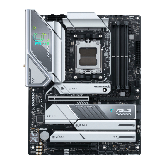
Page 16: Motherboard Layout
Motherboard layout 24.4cm(9.6in) ADD_GEN 2_1 ATX_12V_1 ATX_12V_2 HDMI_DP PLUG_8PIN_PWR DIGI +VRM DRAM BOOT U32G2_C2 U32G2_4 U32G1_C3 U32G2_20 U32G2X2_C18 LAN_U32G2_21 SOCKET AM5 U32G1_1011_2223 M.2(WIFI) FLBK_LED AUDIO Ethernet PCIE SATA 5.0 X4 M.2_1(SOCKET3) 256Mb BIOS 2280 2260 2242 CHA_FAN2 CHA_FAN4 PCIEX16_1 X670 X670 Super PCIE... - Page 17 17. Power button 1-18 18. SPI TPM header (14-1pin) 1-19 19. System Panel header 1-20 20. Thermal Sensor header 1-21 21. Thunderbolt™ header 1-22 22. BIOS FlashBack™ LED 1-23 23. 8-pin Power Plug LED 1-23 24. Q-LEDs 1-24 PRIME X670E-PRO WIFI...
- Page 18 Contact your retailer immediately if the PnP cap is missing, or if you see any damage to the PnP cap/socket contacts/motherboard components. ASUS will shoulder the cost of repair only if the damage is shipment/ transit-related.
- Page 19 A DDR5 memory module is notched differently from a DDR, DDR2, DDR3 or DDR4 module. DO NOT install a DDR, DDR2, DDR3 or DDR4 memory module to the DDR5 slot. Recommended memory configurations DIMM_A1 DIMM_A2 DIMM_A2 DIMM_A2 DIMM_B1 DIMM_B2 DIMM_B2 PRIME X670E-PRO WIFI...
- Page 20 (D/C) from the same vendor. Check with the vendor to get the correct memory modules. • Visit the ASUS website for the latest QVL, and memory frequency support depends on the CPU types. Chapter 1: Product Introduction...
- Page 21 Please refer to the following tables for the recommended VGA configuration and Hyper M.2 configuration. Recommended VGA configuration Slot Description Single VGA Dual VGA PCIe 5.0 x16_1 PCIe 4.0 x16_2 Connect a chassis fan to the chassis fan header when using multiple graphics cards for better thermal environment. PRIME X670E-PRO WIFI...
- Page 22 Additional PCIe bifurcation and M.2 settings for RAID function are also supported when a Hyper M.2 x16 series card is installed. • For full details on the PCIe bifurcation, you may visit the support site at https://www.asus.com/support/FAQ/1037507/. • The Hyper M.2 x16 series card is sold separately •...
- Page 23 The system may become unstable or may not boot up if the power is inadequate. • If you want to use two high-end PCI Express x16 cards, use a PSU with 1000W power or above to ensure the system stability. PRIME X670E-PRO WIFI...
- Page 24 M.2 slots The M.2 slots allow you to install M.2 devices such as M.2 SSD modules. M.2_1(SOCKET3) M.2_4(SOCKET3) M.2_2(SOCKET3) M.2_3(SOCKET3) • AMD Ryzen™ 7000 Series Desktop Processors: - M.2_1 slot supports PCIe 5.0 x4 mode M Key design and type 2242/2260/2280 storage devices.
- Page 25 M.2_2 slot shares bandwidth with SATA6G_1&2. When M.2_2 runs at PCIe x4 mode, SATA6G_1&2 will be disabled. Before creating a RAID set, refer to the RAID Configuration Guide. You can download the RAID Configuration Guide from the ASUS website. PRIME X670E-PRO WIFI 1-11...
- Page 26 USB 3.2 Gen 2 Type-C Front Panel connector ® The USB 3.2 Gen 2 Type-C connector allows you to connect a USB 3.2 Gen 2 ® Type-C module for an additional USB 3.2 Gen 2 Type-C port. The USB 3.2 Gen 2 ®...
- Page 27 The USB 2.0 headers provide data transfer speeds of up to 480 Mb/s. USB_2627 USB_1415 PIN 1 PIN 1 USB_1617 PIN 1 A B C DO NOT connect a 1394 cable to the USB connectors. Doing so will damage the motherboard! The USB 2.0 module is purchased separately. PRIME X670E-PRO WIFI 1-13...
- Page 28 Addressable Gen 2 headers The Addressable Gen 2 headers allow you to connect individually addressable RGB WS2812B LED strips or WS2812B based LED strips. ADD_GEN 2_1 ADD_GEN 2_2 PIN 1 The Addressable Gen 2 header supports WS2812B addressable RGB LED strips (5V/ Data/Ground), with a maximum power rating of 3A (5V) and the addressable headers on this board can handle a combined maximum of 500 LEDs.
- Page 29 RGB LED strip is connected in the correct orientation, and the 12V connector is aligned with the 12V header on the motherboard. • The LED strip will only light up when the system is powered on. • The LED strip is purchased separately. PRIME X670E-PRO WIFI 1-15...
- Page 30 Clear CMOS button The Clear CMOS button allows you to clear the Real Time Clock (RTC) RAM in the CMOS, which contains the date, time, system passwords, and system setup parameters. CLR_CMOS COM Port header The COM (Serial) Port header allows you to connect a COM port module. Connect the COM port module cable to this header, then install the module to a slot opening on the system chassis.
- Page 31 HD Audio. Connect one end of the front panel audio I/O module cable to this header. AAFP PIN 1 HD-audio-compliant pin definition We recommend that you connect a high-definition front panel audio module to this connector to avail of the motherboard’s high-definition audio capability. PRIME X670E-PRO WIFI 1-17...
- Page 32 Power button Press the Power button to power up the system, or put the system into sleep or soft- off mode (depending on the operating system settings). PWR_BUTTON Chapter 1: Product Introduction 1-18...
- Page 33 A TPM system also helps enhance network security, protects digital identities, and ensures platform integrity. PIN 1 VCCSPI S_SPI_TPM_IRQ# S_PLTRST# S_SPI_TPM_CS2# TPM_DETECT_L F_SPI_PWR F_SPI_CS0#_R T_SPI_CLK T_SPI_MISO T_SPI_MOSI F_SPI_HOLD#_R The SPI TPM module is purchased separately. PRIME X670E-PRO WIFI 1-19...
- Page 34 System Panel header The System Panel header supports several chassis-mounted functions. PLED PWRSW SPEAKER PANEL CHASSIS PIN 1 HDD_LED RESET PLED • System Power LED header (PLED) The 2-pin and/or 3-1 pin headers allow you to connect the System Power LED. The System Power LED lights up when the system is connected to a power source, or when you turn on the system power, and blinks when the system is in sleep mode.
- Page 35 Connect the thermal sensor and place it on the device or the motherboard’s component to detect its temperature. T_SENSOR PIN 1 The thermal sensor is purchased separately. PRIME X670E-PRO WIFI 1-21...
- Page 36 Thunderbolt header The Thunderbolt™ header allows you to connect an add-on Thunderbolt™ I/O card that supports Intel®’s Thunderbolt™ Technology, allowing you to connect Thunderbolt™-enabled devices to form a daisy chain-configuration. TB_HEADER PIN 1 • The add-on Thunderbolt™ I/O card and Thunderbolt™ cables are purchased separately.
- Page 37 BIOS flashing is abnormal on using the BIOS FlashBack™ feature Refer to Section 2.2 BIOS update utility 8-pin Power Plug LED The 8-pin Power Plug LED lights up to indicate that the 8-pin power plug is not connected. PLUG_8PIN_PWR PRIME X670E-PRO WIFI 1-23...
- Page 38 Q-LEDs The Q-LEDs check key components (CPU, DRAM, VGA, and booting devices) during the motherboard booting process. If an error is found, the critical component’s LED stays lit up until the problem is solved. CPU (RED) DRAM (YELLOW) VGA (WHITE) BOOT (YELLOW GREEN) The Q-LEDs provide the most probable cause of an error code as a starting point for troubleshooting.
-
Page 39: Building Your Pc System
DO NOT force the CPU into the socket to prevent bending the pins and damaging the CPU. • ASUS will not cover damages resulting from incorrect CPU installation/removal, incorrect CPU orientation/placement, or other damages resulting from negligence by the user. - Page 40 Chapter 2: Basic Installation...
-
Page 41: Cooling System Installation
2.1.2 Cooling system installation • Apply Thermal Interface Material to the CPU cooling system and CPU before you install the cooling system, if necessary. To install a CPU heatsink and fan assembly (Type 1) PRIME X670E-PRO WIFI... - Page 42 To install a CPU heatsink and fan assembly (Type 2) When using this type of CPU fan, remove the screws and the retention module only. Do not remove the plate on the bottom. Chapter 2: Basic Installation...
- Page 43 To install an AIO cooler If you wish to install an AIO cooler, we recommend installing the AIO cooler after installing the motherboard into the chassis. AIO_PUMP CPU_FAN CPU_OPT PRIME X670E-PRO WIFI...
-
Page 44: Dimm Installation
2.1.3 DIMM installation To remove a DIMM Chapter 2: Basic Installation... -
Page 45: Installation
M.2 slots if you wish to install an M.2 to another M.2 slot. • Use a Phillips screwdriver when removing or installing the screws or screw stands mentioned in this section. • The M.2 is purchased separately. Loosen the screws from the M.2 heatsinks. Lift and remove the heatsinks. PRIME X670E-PRO WIFI... - Page 46 Install your M.2 to your M.2 slot. The steps may differ between installing M.2 of different lengths, please refer to the different types and their installation steps below: • To install an M.2 to M.2_1, M.2_3, M.2_4 slot For 2280 length (optional) Install the bundled M.2 rubber pad if you are installing a single sided M.2 storage device.
- Page 47 OPTIONAL PRIME X670E-PRO WIFI...
- Page 48 • To install an M.2 to M.2_2 slot For 2280, 22110 length (optional) Remove the pre-installed removable M.2 Q-Latch screw at the 2280 length screw hole. Follow step A only when you wish to install an 22110 length M.2 to M.2_2. (optional) Install the bundled rubber for M.2 if you are installing a single sided M.2 storage device.
- Page 49 M.2 to. Rotate and adjust the M.2 Q-latch so that the handle points away from the M.2 slot. Install your M.2 to the M.2 slot. Rotate the M.2 Q-Latch clockwise to secure the M.2 in place. PRIME X670E-PRO WIFI 2-11...
- Page 50 Remove the plastic film from the thermal pad on the bottom of the heatsinks. If the thermal pad on the M.2 heatsink becomes damaged and needs to replaced, we recommend replacing it with a thermal pad with a thickness of 1.25mm. Replace the heatsinks.
-
Page 51: Motherboard Installation
Place the motherboard into the chassis, ensuring that its rear I/O ports are aligned to the chassis’ rear I/O panel. Place nine (9) screws into the holes indicated by circles to secure the motherboard to the chassis. DO NOT over tighten the screws! Doing so can damage the motherboard. PRIME X670E-PRO WIFI 2-13... -
Page 52: Atx Power Connection
2.1.6 ATX power connection Ensure to connect the 8-pin power plug, or connect both 8-pin power plugs. Chapter 2: Basic Installation 2-14... -
Page 53: Sata Device Connection
2.1.7 SATA device connection PRIME X670E-PRO WIFI 2-15... -
Page 54: Front I/O Connector
2.1.8 Front I/O connector To install front panel connector To install USB 3.2 Gen 2 Type-C ® connector USB 3.2 Gen 2 Type-C ® This connector will only fit in one orientation. Push the connector until it clicks into place. To install USB 2.0 connector To install USB 3.2 Gen 1 connector USB 2.0... -
Page 55: Expansion Card Installation
2.1.9 Expansion card installation To install PCIe x16 cards To install PCIe x4 card PRIME X670E-PRO WIFI 2-17... - Page 56 To install Thunderbolt™ series card 6-pin PCIe power connector USB Type-C ® port connects to Thunderbolt devices MiniDP in port connects to DP out port on the motherboard or a VGA card USB 2.0 header Thunderbolt™ header The Thunderbolt™ card can only be used when installed to the PCIe x4 slot. Ensure to install your Thunderbolt™...
- Page 57 To release an expansion card using the PCIe Slot Q-Release: Slightly lift the expansion card with one hand and press the PCIe Slot Q-Release button with the other hand. This should release the expansion card so that you can remove it with ease. PRIME X670E-PRO WIFI 2-19...
-
Page 58: Wi-Fi Moving Antenna Installation
2.1.10 Wi-Fi moving antenna installation Installing the ASUS Wi-Fi moving antenna Connect the bundled Wi-Fi ASUS moving antenna connectors to the Wi-Fi ports at the back of the chassis. • Ensure that the Wi-Fi moving antenna is securely installed to the Wi-Fi ports. -
Page 59: Bios Update Utility
• Updating BIOS may have risks. If the BIOS program is damaged during the process and results to the system’s failure to boot up, please contact your local ASUS Service Center. PRIME X670E-PRO WIFI... -
Page 60: Motherboard Rear And Audio Connections
For more information on using the BIOS FlashBack™ feature, please refer to https://www.asus.com/support/, or by scanning the QR code below. Motherboard rear and audio connections 2.3.1 Rear I/O connection Rear panel connectors DisplayPort USB 3.2 Gen 2 Type-A ports 4, 20, and 21 Ethernet port* USB 3.2 Gen 1 Type-A ports 10, 11, and 22... - Page 61 Front Speaker Front Speaker Front Speaker Front Speaker (Rear panel) Pink – – – – (Rear panel) Black Rear Speaker Rear Speaker Rear Speaker – (Rear panel) Orange Center/ Center/ – – (Rear panel) Subwoofer Subwoofer PRIME X670E-PRO WIFI 2-23...
-
Page 62: Audio I/O Connections
2.3.2 Audio I/O connections Audio I/O ports Connect to Headphone and Mic Connect to 2-channel Speakers Connect to 4-channel Speakers Chapter 2: Basic Installation 2-24... - Page 63 Connect to 5.1-channel Speakers Connect to 7.1-channel Speakers PRIME X670E-PRO WIFI 2-25...
-
Page 64: Starting Up For The First Time
Starting up for the first time After making all the connections, replace the system case cover. Ensure that all switches are off. Connect the power cord to the power connector at the back of the system chassis. Connect the power cord to a power outlet that is equipped with a surge protector. Turn on the devices in the following order: Monitor External storage devices (starting with the last device on the chain) -
Page 65: Chapter 3: Bios And Raid Support
Knowing BIOS The new ASUS UEFI BIOS is a Unified Extensible Interface that complies with UEFI architecture, offering a user-friendly interface that goes beyond the traditional keyboard- only BIOS controls to enable a more flexible and convenient mouse input. You can easily navigate the new UEFI BIOS with the same smoothness as your operating system. -
Page 66: Bios Setup Program
BIOS Setup program Use the BIOS Setup to update the BIOS or configure its parameters. The BIOS screens include navigation keys and brief onscreen help to guide you in using the BIOS Setup program. Entering BIOS at startup To enter BIOS Setup at startup, press <Delete> or <F2> during the Power-On Self Test (POST). -
Page 67: Asus Ez Flash 3
ASUS EZ Flash 3 The ASUS EZ Flash 3 feature allows you to update the BIOS without using an OS-based utility. Ensure to load the BIOS default settings to ensure system compatibility and stability. Select the Load Optimized Defaults item under the Exit menu or press hotkey <F5>. -
Page 68: Asus Crashfree Bios 3
ASUS CrashFree BIOS 3 The ASUS CrashFree BIOS 3 utility is an auto recovery tool that allows you to restore the BIOS file when it fails or gets corrupted during the updating process. You can restore a corrupted BIOS file using a USB flash drive that contains the BIOS file. -
Page 69: Raid Configurations
For more information on configuring your RAID sets, please refer to the RAID Configuration Guide which you can find at https://www.asus.com/support, or by scanning the QR code. RAID definitions Volume provides the ability to link-together storage from one or several disks, regardless of the size of the space on those disks. - Page 70 Chapter 3: BIOS and RAID Support...
-
Page 71: Appendix
Appendix Notices FCC Compliance Information Responsible Party: Asus Computer International Address: 48720 Kato Rd., Fremont, CA 94538, USA Phone / Fax No: (510)739-3777 / (510)608-4555 This device complies with part 15 of the FCC Rules. Operation is subject to the following two conditions: (1) This device may not cause harmful interference, and (2) this device must accept any interference received, including interference that may cause undesired operation. - Page 72 Compliance Statement of Innovation, Science and Economic Development Canada (ISED) This device complies with Innovation, Science and Economic Development Canada licence exempt RSS standard(s). Operation is subject to the following two conditions: (1) this device may not cause interference, and (2) this device must accept any interference, including interference that may cause undesired operation of the device.
- Page 73 Tenez cet appareil à distance du ventre des femmes enceintes et du bas-ventre des adolescents. PRIME X670E-PRO WIFI...
- Page 74 ASUS products sold in Vietnam, on or after September 23, 2011,meet the requirements of the Vietnam Circular 30/2011/TT-BCT. Các sản phẩm ASUS bán tại Việt Nam, vào ngày 23 tháng 9 năm2011 trở về sau, đều phải đáp ứng các yêu cầu của Thông tư 30/2011/TT-BCT của Việt Nam.
- Page 75 Accessories that came with this product have been designed and verified for the use in connection with this product. Never use accessories for other products to prevent the risk of electric shock or fire. 安全上のご注意 付属品は当該専用品です。 他の機器には使用しないでください。 機器の破損もしくは、 火災や感 電の原因となることがあります。 PRIME X670E-PRO WIFI...
- Page 76 ASUSTek Computer Inc. hereby declares that this device is in compliance with the essential requirements and other relevant provisions of The Radio Equipment Regulations 2017 (S.I. 2017/1206). Full text of UKCA declaration of conformity is available at https://www.asus.com/support/. The WiFi operating in the band 5150-5350MHz shall be restricted to indoor use for the country listed below: UKCA RF Output table (The Radio Equipment Regulations 2017) T99H245.10 (Model: MT7921K):...
- Page 77 постановления на свързаната Директива 2014/53/EC. Пълният текст на ЕС der Richtlinie 2014/53/EU übereinstimmt. Der gesamte Text der EU- декларация за съвместимост е достъпен на адрес Konformitätserklärung ist verfügbar unter: https://www.asus.com/support/. https://www.asus.com/support/. Der WLAN-Betrieb im Band von 5150-5350 MHz ist für die in der unteren WiFi, работеща...
- Page 78 Käesolevaga kinnitab ASUSTek Computer Inc, et seade vastab direktiivi zahtjevima i ostalim odgovarajućim odredbama direktive 2014/53/EU. Cijeli 2014/53/EÜ olulistele nõuetele ja teistele asjakohastele sätetele. EL tekst EU izjave o sukladnosti dostupan je na https://www.asus.com/support/. vastavusdeklaratsiooni täistekst on saadaval veebisaidil https://www.asus.com/support/.
- Page 79 Az EU megfelelőségi nyilatkozat teljes szövegét a ASUSTek Computer Inc. erklærer herved at denne enheten er i samsvar med következő weboldalon tekintheti meg: https://www.asus.com/support/. hovedsaklige krav og andre relevante forskrifter i direktivet 2014/53/EU. Az 5150-5350 MHz-es sávban működő Wi-Fi-t beltéri használatra kell Fullstendig tekst for EU-samsvarserklæringen finnes på:...
- Page 80 Direktive 2014/53/EU. Polno 5150-5350 MHz arasındaki WiFi çalışması, tabloda listelenen ülkeler için iç besedilo izjave EU o skladnosti je na voljo na https://www.asus.com/support/. mekân kullanımıyla kısıtlanacaktır. WiFi, ki deluje v pasovnem območju 5150–5350 MHz, mora biti v državah, Düşük Güç...
- Page 81 5150 - 5350 MHz 21.52 dBm WiFi 5470 - 5725 MHz 21.46 dBm 5725 - 5850 MHz 10.08 dBm 5925 - 6425 MHz 20.14 dBm Bluetooth 2402 - 2480 MHz 14.15 dBm * Receiver category 1 PRIME X670E-PRO WIFI A-11...
-
Page 82: Warranty
• ASUS offers a voluntary manufacturer’s Commercial Guarantee. • ASUS dragovoljno nudi komercijalno proizvođačko jamstvo. • ASUS reserves the right to interpret the provisions of the ASUS • ASUS zadržava prava na tumačenje odredbi ASUS komercijalnog Commercial Guarantee. jamstva. •... - Page 83 • ASUS tilbyr som produsent en frivillig kommersiell garanti. • Bảo hành thương mại này của ASUS được cung cấp độc lập và ngoài • ASUS forbeholder seg retten til å tolke bestemmelsene i ASUS sin Bảo đảm pháp lý theo luật định và không có cách nào ảnh hưởng đến kommersielle garanti.
-
Page 84: Asus Contact Information
Address: 1F., No. 15, Lide Rd., Beitou Dist., Taipei City 112, Taiwan ASUS COMPUTER INTERNATIONAL (America) Address: 48720 Kato Rd., Fremont, CA 94538, USA ASUS COMPUTER GmbH (Germany and Austria) Address: Harkortstrasse 21-23, 40880 Ratingen, Germany ASUSTeK (UK) LIMITED Address: 1st Floor, Sackville House, 143-149 Fenchurch Street, London, EC3M 6BL,...
Need help?
Do you have a question about the X670E-PRO WIFI and is the answer not in the manual?
Questions and answers
how do i activate wifi 7 after the system is completed?