Table of Contents
Advertisement
Advertisement
Table of Contents

Related Manuals for Asus SABERTOOTH X58


Summary of Contents for Asus SABERTOOTH X58
- Page 1 SABERTOOTH...
- Page 2 Product warranty or service will not be extended if: (1) the product is repaired, modified or altered, unless such repair, modification of alteration is authorized in writing by ASUS; or (2) the serial number of the product is defaced or missing.
-
Page 3: Table Of Contents
Contents Contents ... iii Notices ... viii Safety information ... ix About this guide ... x SABERTOOTH X58 specifications summary ... xii Chapter 1: Product introduction Welcome! ... 1-1 Package contents... 1-1 Special features... 1-2 1.3.1 Product highlights... 1-2 1.3.2 “TUF ENGINE!”... -
Page 4: Contents
Internal connectors... 2-29 ASUS Q-Connector (system panel) ... 2-37 BIOS setup ASUS Update utility... 3-2 ASUS EZ Flash 2 utility ... 3-4 ASUS CrashFree BIOS 3 utility... 3-5 BIOS menu screen ... 3-6 Menu bar ... 3-6 Navigation keys ... 3-7 Menu items... - Page 5 PCIE Frequency ... 3-14 3.5.8 DRAM Frequency... 3-14 3.5.9 UCLK Frequency... 3-14 3.5.10 QPI Link Data Rate ... 3-14 3.5.11 ASUS/3rd Party UI Priority ... 3-14 3.5.12 DRAM Timing Contro ... 3-14 3.5.13 CPU Voltage Control ... 3-16 3.5.14 CPU Voltage... 3-16 3.5.15 CPU PLL Voltage ...
- Page 6 5.1.3 5.1.4 Boot Device Priority... 3-31 Boot Settings Configuration ... 3-32 Security ... 3-33 ASUS EZ Flash 2 ... 3-35 ASUS O.C. Profile ... 3-35 AI NET 2 ... 3-37 Drive Xpert Configuration ... 3-37 Software support Running the support DVD ... 4-1 Obtaining the software manuals...
- Page 7 Contents 5.1.5 Installing the device drivers ... 5-4 5.1.6 Enabling the ATI NVIDIA SLI™ technology ... 5-6 ® 5.2.1 Requirements ... 5-6 5.2.2 Installing two SLI-ready graphics cards ... 5-6 5.2.3 Installing the device drivers ... 5-7 5.2.4 Enabling the NVIDIA CrossFireX™...
-
Page 8: Canadian Department Of Communications Statement
Complying with the REACH (Registration, Evaluation, Authorisation, and Restriction of Chemicals) regulatory framework, we published the chemical substances in our products at ASUS REACH website at http://csr.asus.com/english/REACH.htm. DO NOT throw the motherboard in municipal waste. This product has been designed to enable proper reuse of parts and recycling. -
Page 9: Electrical Safety
Safety information Electrical safety • To prevent electrical shock hazard, disconnect the power cable from the electrical outlet before relocating the system. • When adding or removing devices to or from the system, ensure that the power cables for the devices are unplugged before the signal cables are connected. If possible, disconnect all power cables from the existing system before you add a device. -
Page 10: About This Guide
Where to find more information Refer to the following sources for additional information and for product and software updates. ASUS websites The ASUS website provides updated information on ASUS hardware and software products. Refer to the ASUS contact information. Optional documentation Your product package may include optional documentation, such as warranty flyers, that may have been added by your dealer. -
Page 11: Conventions Used In This Guide
Conventions used in this guide To ensure that you perform certain tasks properly, take note of the following symbols used throughout this manual. DANGER/WARNING: Information to prevent injury to yourself when trying to complete a task. CAUTION: Information to prevent damage to the components when trying to complete a task. -
Page 12: Sabertooth X58 Specifications Summary
* Hyper DIMM support is subject to the physical characteristics of individual CPUs. ** Refer to www.asus.com or this user manual for the Memory QVL (Qualified Vendors Lists) 2 x PCI Express 2.0 x16 slots (dual at x16 / x16 mode) - Page 13 “Safe & Stable!” Guardian Angel - MemOK! True USB 3.0 support True SATA 6.0 Gb/s RAID support ASUS Q-Connector ASUS Q-Shield ASUS Q-LED (CPU, DRAM, VGA, Boot Device LED) ASUS Q-Slot ASUS Q-DIMM ASUS CrashFree BIOS 3 ASUS EZ Flash 2 ASUS MyLogo 2™...
- Page 14 1 x MemOK! button 16 Mb Flash ROM, AMI BIOS, PnP, DMI 2.0, WfM 2.0, SM BIOS 2.5, ACPI 2.0a, Multi-language BIOS, ASUS EZ Flash 2, ASUS CrashFree BIOS 3 WfM 2.0, DMI 2.0, WOL by PME, WOR by PME, PXE Drivers...
-
Page 15: Chapter 1: Product Introduction
Thank you for buying an ASUS The motherboard delivers a host of new features and latest technologies, making it another standout in the long line of ASUS quality motherboards! Before you start installing the motherboard, and hardware devices on it, check the items in your package with the list below. -
Page 16: Special Features
Green ASUS This motherboard and its packaging comply with the European Union’s Restriction on the use of Hazardous Substances (RoHS). This is in line with the ASUS vision of creating environment-friendly and recyclable products/packaging to safeguard consumers’ health while minimizing the impact on the environment. -
Page 17: Tuf Engine!" Power Design
ASUS Fan Xpert ASUS Fan Xpert intelligently allows you to adjust both the CPU and chassis fan speeds according to different ambient temperatures caused by different climate conditions in different geographic regions and your PC’s loading. The built-in variety of useful profiles offer flexible controls of fan speed to achieve a quiet and cool environment. -
Page 18: Asus Mylogo2
Refer to page 2-37 for details. ASUS EZ-Flash 2 ASUS EZ Flash 2 is a user-friendly utility that allows you to update the BIOS without using a bootable floppy disk or an OS-based utility. Refer to page 3-4 for details. ASUS O.C. Profile The motherboard features the ASUS O.C. -
Page 19: Chapter 2: Hardware Information
• • • • ASUS SABERTOOTH X58 Chapter 2 Unplug the power cord from the wall socket before touching any component. Before handling components, use a grounded wrist strap or touch a safely grounded object or a metal object, such as the power supply case, to avoid damaging them due to static electricity. -
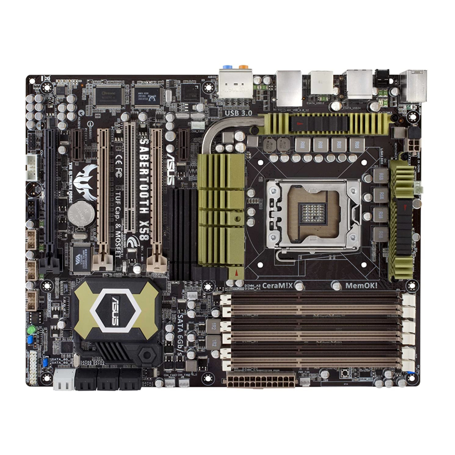
Page 20: Motherboard Overview
Motherboard overview 2.2.1 Motherboard layout Refer to 2.8 Connectors for more information about rear panel connectors and internal connectors. Chapter 2: Hardware information... -
Page 21: Layout Contents
USB connectors (10-1 pin USB78, USB910, USB1112) IEEE 1394a port connector (10-1 pin IE1394_2) Digital audio connector (4-1 pin SPDIF_OUT) Serial port connector (10-1 pin COM1) Front panel audio connector (10-1 pin AAFP) ASUS SABERTOOTH X58 Page 2-35 2-33 2-10... -
Page 22: Placement Direction
2.2.3 Placement direction When installing the motherboard, ensure that you place it into the chassis in the correct orientation. The edge with external ports goes to the rear part of the chassis as indicated in the image below. 2.2.4 Screw holes Place nine screws into the holes indicated by circles to secure the motherboard to the chassis. -
Page 23: Central Processing Unit (Cpu)
Contact your retailer immediately if the PnP cap is missing, or if you see any damage to the PnP cap/socket contacts/motherboard components. ASUS will shoulder the cost of repair only if the damage is shipment/ transit-related. - Page 24 Press the load lever with your thumb (A), then move it to the left (B) until it is released from the retention tab. To prevent damage to the socket pins, do not remove the PnP cap unless you are installing a CPU. Lift the load lever in the direction of the arrow to a 135º...
- Page 25 To prevent contaminating the paste, DO NOT spread the paste with your finger directly. Close the load plate (A), then push the load lever (B) until it snaps into the retention tab. ASUS SABERTOOTH X58 CPU notch Alignment key Gold...
-
Page 26: Installing The Cpu Heatsink And Fan
2.3.2 Installing the CPU heatsink and fan The Intel LGA1366 processor requires a specially designed heatsink and fan assembly to ® ensure optimum thermal condition and performance. • When you buy a boxed Intel heatsink assembly. If you buy a CPU separately, ensure that you use only Intel multi-directional heatsink and fan. -
Page 27: Uninstalling The Cpu Heatsink And Fan
Rotate each fastener counterclockwise. Pull up two fasteners at a time in a diagonal sequence to disengage the heatsink and fan assembly from the motherboard. Carefully remove the heatsink and fan assembly from the motherboard. ASUS SABERTOOTH X58... -
Page 28: System Memory
System memory 2.4.1 Overview The motherboard comes with six Double Data Rate 3 (DDR3) Dual Inline Memory Modules (DIMM) sockets. A DDR3 module has the same physical dimensions as a DDR2 DIMM but is notched differently to prevent installation on a DDR2 DIMM socket. DDR3 modules are developed for better performance with less power consumption. -
Page 29: Memory Configurations
• For system stability, use a more efficient memory cooling system to support a full memory load (6 DIMMs) or overclocking condition. ASUS SABERTOOTH X58 CPU spec, DIMM voltage below 1.65V is recommended to protect ® ® support site at... - Page 30 SABERTOOTH X58 Motherboard Qualified Vendors Lists (QVL) DDR3-1866 MHz capability Vendor Part No. CORSAIR TR3X3G1866C9DVer4.1(XMP) CORSAIR TR3X6G1866C9DVer4.1(XMP) G.SKILL F3-15000CL9D-4GBRH (XMP) G.SKILL F3-15000CL9D-4GBTD(XMP) KINGSTON KHX1866C9D3T1K3/6GX(XMP) OCZ3RPR1866C9LV3GK OCZ3P1866LV4GK OCZ3P1866C9LV6GK OCZ3RPR1866C9LV6GK Super Talent W1866UX2GB(XMP) Patriot PVS32G1866LLK(XMP) BoxP/N:TXD34096M1866HC7DC-L Team (TXD32048M1866HC7-L)(XMP) SABERTOOTH X58 Motherboard Qualified Vendors Lists (QVL)
- Page 31 SABERTOOTH X58 Motherboard Qualified Vendors Lists (QVL) DDR3-1600MHz capability Vendor Part No. Size A-DATA AD31600G001GMU A-DATA AX3U1600GB1G9-AG 2GB(2 x 1GB) SS N/A A-DATA AX3U1600PB1G8-2P 2GB(2 x 1GB) SS N/A A-DATA AD31600E001GMU 3GB(3 x 1GB) SS N/A A-DATA AX3U1600GB1G9-3G 3GB(3 x 1GB) SS N/A...
- Page 32 SABERTOOTH X58 Motherboard Qualified Vendors Lists (QVL) DDR3-1333MHz capability Vendor Part No. A-DATA AD3133301GOU A-DATA AD31333002GOU A-DATA AD3U1333B2G9-2 A-DATA AX3U1333PB2G7-2P A-DATA AD3U1333C4G9-B A-DATA AD31333E002G0U A-DATA AX3U1333PB2G7-3P CORSAIR TR3X3G1333C9 (Ver2.1) CORSAIR CM3X1024-1333C9DHX BoxP/N:TWIN3X2048-1333C9 CORSAIR (CM3X1024-1333C9)Ver1.1 BoxP/N:TW3X4G1333C9DHX CORSAIR (CM3X2048-1333C9DHX)Ver3.2 CORSAIR TR3X6G1333C9 (Ver2.1) Crucial CT12864BA1339.8FF...
- Page 33 SABERTOOTH X58 Motherboard Qualified Vendors Lists (QVL) DDR3-1333MHz capability (continued) Vendor Part No. Size OCZ3RPX1333EB4GK 4GB(2 x 2GB) DS N/A OCZ3G1333LV6GK 6GB(3 x 2GB) DS N/A OCZ3P1333LV6GK 6GB(3 x 2GB) DS N/A OCZX1333LV6GK(XMP) 6GB(3 x 2GB) DS NA SAMSUNG M378B2873DZ1-CH9...
-
Page 34: Ddr3-1066Mhz Capability
SABERTOOTH X58 Motherboard Qualified Vendors Lists (QVL) DDR3-1066MHz capability Vendor Part No. CORSAIR CM3X1024-1066C7 Crucial CT12864BA1067.8FF Crucial CT12864BA1067.8SFD Crucial CT12872BA1067.9FF Crucial CT25664BA1067.16FF Crucial CT25664BA1067.16SFD Crucial CT25672BA1067.18FF ELPIDA EBJ10UE8BAW0-AE-E ELPIDA EBJ11RD8BAFA-AE-E ELPIDA EBJ11UD8BAFA-AG-E ELPIDA EBJ21UE8BAW0-AE-E Hynix HMT112U6AFP8C-G7N0 Hynix HYMT112U64ZNF8-G7 Hynix HMT125U6AFP8C-G7N0... -
Page 35: Installing A Dimm
Always insert the DIMM into the socket VERTICALLY to prevent DIMM notch damage. 2.4.4 Removing a DIMM Press the retaining clip outward to unlock the DIMM. Remove the DIMM from the socket. ASUS SABERTOOTH X58 DIMM notch DIMM slot key Unlocked retaining clip Locked Retaining Clip 2-17... -
Page 36: Expansion Slots
Expansion slots In the future, you may need to install expansion cards. The following subsections describe the slots and the expansion cards that they support. Ensure to unplug the power cord before adding or removing expansion cards. Failure to do so may cause you physical injury and damage motherboard components. -
Page 37: Irq Assignments For This Motherboard
– USB_4 shared USB_5 – shared USB_6 USB 2.0_1 – USB 2.0_2 – SATA_1 – SATA _2 – Audio – ASUS SABERTOOTH X58 – – – – – – – shared – – – – – – – – –... -
Page 38: Pci Slot
2.5.4 PCI slot The PCI slot supportd cards such as a LAN card, SCSI card, USB card, and other cards that comply with PCI specifications. Refer to the figure below for the location of the slot. 2.5.5 PCI Express x16 / x1 slots This motherboard supports PCI Express x16 / x1 network cards, SCSI cards and other cards that comply with the PCI Express specifications. - Page 39 • Connect a chassis fan to the motherboard connector labeled CHA_FAN1/2/3 when using multiple graphics cards for better thermal environment. See page 2-33 for details. ASUS SABERTOOTH X58 PCIe 2.0 x16_2 PCIe x16_3 x16 (Single VGA) x4 or x1 (when PCI...
-
Page 40: Clear Rtc Ram
CMOS RTC RAM data. The onboard button cell battery powers the RAM data in CMOS, which include system setup information such as system passwords. ® SABERTOOTH X58 Clear RTC RAM To erase the RTC RAM Turn OFF the computer and unplug the power cord. - Page 41 CPU permanently. We recommend you install the DIMMs with the voltage requirement below 1.65V. • The system may need a better cooling system (for example, a water-cooling system) to work stably under high voltage settings. ASUS SABERTOOTH X58 OV_CPU OV_DRAM_BUS up to 1.70V up to 2.00V up to 2.10V...
-
Page 42: Onboard Switch
BIOS has been restored to its default settings. • We recommend that you download and update to the latest BIOS version from the ASUS website at www.asus.com after using the MemOK! function. 2-24 ® OS environment will reboot the computer... -
Page 43: Connectors
JMB 36x ATA Controller item in the BIOS setting to [Enabled] and install the JMicron JMB36X Controller Driver from the motherboard support DVD. Refer to section 3.6.3 Onboard Devices Configuration for details. ASUS SABERTOOTH X58 IEEE 1394a port Power External SATA port External SATA port 10. -
Page 44: Audio I/O Connections
* LAN port LED indications Activity Link LED Status Description No link ORANGE Linked BLINKING Data activity ** Audio 2, 4, 6, or 8-channel configuration Headset Port 2-channel Light Blue Line In Lime Line Out Pink Mic In Orange – Black –... - Page 45 Connect to Stereo Speakers Connect to 2.1 channel Speakers Connect to 4.1-channel Speakers ASUS SABERTOOTH X58 2-27...
- Page 46 Connect to 5.1-channel Speakers Connect to 7.1-channel Speakers 2-28 Chapter 2: Hardware information...
-
Page 47: Internal Connectors
When using hot-plug and NCQ, set the Configure SATA as in the BIOS to [AHCI]. • See section 3.4.2 Storage Configuration for details. ASUS SABERTOOTH X58 Matrix Storage Technology through the onboard Intel ® XP Service Pack 2 or later version before using Serial ®... - Page 48 Marvell Serial ATA 6.0 Gb/s connectors ® (7-pin SATA_6G_1, 7-pin SATA_6G_2 [gray]) These connectors are for the Serial ATA 6.0 Gb/s signal cables for Serial ATA 6.0 Gb/s hard disk drives. • These connectors are set to IDE Mode by default. When using hot-plug and NCQ, set the Marvell 9128 Controller item in the BIOS to [AHCI Mode].
- Page 49 Never connect a 1394 cable to the USB connectors. Doing so will damage the motherboard! You can connect the front panel USB cable to the ASUS Q-Connector (USB, blue) first, and then install the Q-Connector (USB) to the USB connector onboard if your chassis supports front panel USB ports.
- Page 50 IEEE 1394a port connector (10-1 pin IE1394_2) This connector is for an IEEE 1394a port. Connect the IEEE 1394a module cable to this connector, then install the module to a slot opening at the back of the system chassis. Never connect a USB cable to the IEEE 1394a connector. Doing so will damage the motherboard! The IEEE 1394a module is purchased separately.
- Page 51 • The CPU_FAN connector supports the CPU fan of maximum 2A (24 W) fan power. • Only the CPU_FAN, CHA_FAN1 and CHA_FAN2 connectors support the ASUS Fan Xpert feature. • If you install two VGA cards, we recommend that you plug the rear chassis fan cable to the motherboard connector labeled CHA_FAN1/2/3 for better thermal environment.
- Page 52 Digital audio connector (4-1 pin SPDIF_OUT) This connector is for an additional Sony/Philips Digital Interface (S/PDIF) port. Connect the S/PDIF Out module cable to this connector, then install the module to a slot opening at the back of the system chassis. The S/PDIF module is purchased separately.
-
Page 53: Atx Power Connectors
1000W power or above to ensure the system stability. • If you are uncertain about the minimum power supply requirement for your system, refer to the Recommended Power Supply Wattage Calculator at http://support.asus. com/PowerSupplyCalculator/PSCalculator.aspx?SLanguage=en-us for details. PSU suggested list: Seventeam ST-522HLP... -
Page 54: System Panel Connector
System panel connector (20-8 pin PANEL) This connector supports several chassis-mounted functions. • System power LED (2-pin PLED) This 2-pin connector is for the system power LED. Connect the chassis power LED cable to this connector. The system power LED lights up when you turn on the system power, and blinks when the system is in sleep mode. -
Page 55: Asus Q-Connector (System Panel)
2.8.4. ASUS Q-Connector (system panel) Use the ASUS Q-Connector to connect/disconnect the chassis front panel cables. To install the ASUS Q-Connector: Connect the front panel cables to the ASUS Q-Connector. Refer to the labels on the Q-Connector to know the detailed pin definitions, and then match them to their respective front panel cable labels. -
Page 56: Onboard Leds
Onboard LEDs Standby Power LED The motherboard comes with a standby power LED. The green LED lights up to indicate that the system is ON, in sleep mode, or in soft-off mode. This is a reminder that you should shut down the system and unplug the power cable before removing or plugging in any motherboard component. -
Page 57: Starting Up For The First Time
BIOS setting. Pressing the power switch for more than four seconds lets the system enter the soft-off mode regardless of the BIOS setting. Refer to section 3.7 Power menu in Chapter 3 for details. ASUS SABERTOOTH X58 Description VGA detected... - Page 58 2-40 Chapter 2: Hardware information...
-
Page 59: Chapter 3: Bios Setup
Refer to the corresponding sections for details on these utilities. Save a copy of the original motherboard BIOS file to a USB flash disk in case you need to restore the BIOS in the future. Copy the original motherboard BIOS using the ASUS Update utility. -
Page 60: Asus Update Utility
3.2.1 ASUS Update utility The ASUS Update is a utility that allows you to manage, save, and update the motherboard BIOS in Windows environment. The ASUS Update utility allows you to: ® • Save the current BIOS file • Download the latest BIOS file from the Internet •... - Page 61 Auto Select. Click Next. Follow the onscreen instructions to complete the update process. The ASUS Update utility is capable of updating itself through the Internet. Always update the utility to avail all its features. Updating the BIOS through a BIOS file...
-
Page 62: Asus Ez Flash 2 Utility
3.2.2 ASUS EZ Flash 2 utility The ASUS EZ Flash 2 feature allows you to update the BIOS without having to use a bootable floppy disk or an OS-based utility. Before you start using this utility, download the latest BIOS from the ASUS website at www.asus.com. -
Page 63: Asus Crashfree Bios 3 Utility
The BIOS file in the motherboard support DVD may be older than the BIOS file published on the ASUS official website. If you want to use the newer BIOS file, download the file at support.asus.com and save it to a USB flash drive. -
Page 64: Bios Setup Program
For changing the advanced power management (APM) configuration Boot For changing the system boot configuration Tools For configuring options for special functions Exit For selecting the exit options and loading default settings Configuration fields SABERTOOTH X58 BIOS Setup Advanced Power Boot [15:57:25] [Wed 06/30/2010] [English] [HDT722516DLA380]... -
Page 65: Navigation Keys
<Page Up> / <Page Down> keys to display the other items on the screen. 3.3.9 General help At the top right corner of the menu screen is a brief description of the selected item. ASUS SABERTOOTH X58 BIOS SETUP UTILITY Main Ai Tweaker Advanced... -
Page 66: Main Menu
The BIOS automatically detects the values opposite the dimmed items (Device, Vendor, Size, LBA Mode, Block Mode, PIO Mode, Async DMA, Ultra DMA, and SMART Monitoring). These values are not user-configurable. These items show N/A if no SATA device is installed in the system. SABERTOOTH X58 BIOS Setup Advanced Power Boot... - Page 67 Sets the controller to combine two 16-bit reads from the hard disk into a single 32-bit double word transfer to the processor. This makes more efficient use of the PCI bus as fewer transactions are needed for the transfer of a particular amount of data. [Disabled] Disables this function. ASUS SABERTOOTH X58...
-
Page 68: Storage Configuration
Disables this function. SATA Detect Time Out (Sec) [35] Selects the time out value for detecting ATA/ATAPI devices from the following options: [0] [5] [10] [15] [20] [25] [30] [35] 3-10 SABERTOOTH X58 BIOS Setup [Enhanced] [IDE] [Disabled] [35] Chapter 3: BIOS setup... -
Page 69: Ahci Configuration
AHCI Configuration This menu is the section for AHCI configuration. It appears only when you set the item Configure SATA as from the submenu of SATA Configuration to [AHCI]. SABERTOOTH X58 BIOS Setup Main AHCI Settings AHCI CD/DVD Boot Time out... -
Page 70: Ai Tweaker Menu
Ai Overclock Tuner [Auto] Allows you to select the CPU overclocking options to achieve the desired CPU internal frequency. Select any of these preset overclocking configuration options: Manual Auto D.O.C.P X.M.P. 3-12 SABERTOOTH X58 BIOS Setup Advanced Power Boot [Auto] [Auto] [Enabled] [Enabled]... -
Page 71: Xtreme Phase Full Power Mode
Allows you to adjust the CPU operating frequency to enhance the system performance. Use the <+> and <-> keys to adjust the value. You can also key in the desired value using the numeric keypad. The values range from 100 to 500. ASUS SABERTOOTH X58 3-13... -
Page 72: Pcie Frequency
Configuration options: [Auto] [Slow Mode] [4800MT/s] [5866MT/s] [6400MT/s] 3.5.11 ASUS/3rd Party UI Priority [ASUS Utility] [ASUS Utility] Prioritizes the usage of ASUS utilities. Other 3rd party OC utilities may not be full-functioned. [3rd Party Utility] Prioritizes 3rd party OC utilities. ASUS utilities can’t be launched. 3.5.12 DRAM Timing Control [Auto] The items in this menu allow you to set the DRAM timing control features. - Page 73 Configuration options: [Auto] [2 DRAM Clock] – [14 DRAM Clock] DRAM READ to WRITE Delay(DR) [Auto] Configuration options: [Auto] [2 DRAM Clock] – [14 DRAM Clock] DRAM READ to WRITE Delay(SR) [Auto] Configuration options: [Auto] [2 DRAM Clock] – [14 DRAM Clock] ASUS SABERTOOTH X58 3-15...
-
Page 74: Cpu Voltage Control
DRAM READ to READ Delay(DD) [Auto] Configuration options: [Auto] [2 DRAM Clock] – [9 DRAM Clock] DRAM READ to READ Delay(DR) [Auto] Configuration options: [Auto] [2 DRAM Clock] – [9 DRAM Clock] DRAM READ to READ Delay(SR) [Auto] Configuration options: [Auto] [4 DRAM Clock] [6 DRAM Clock] DRAM WRITE to WRITE Delay(DD) [Auto] Configuration options: [Auto] [2 DRAM Clock] –... -
Page 75: Ioh Voltage
QPI/DRAM Core 1.20000V– Voltage 1.26875V IOH Voltage 1.10V–1.18V IOH PCIE Voltage 1.50V–1.58V ICH Voltage 1.10V–1.20V ICH PCIE Voltage 1.50V–1.60V DRAM Bus Voltage 1.50V–1.64V ASUS SABERTOOTH X58 Yellow Purple 1.23125V– 1.30000V– 1.29375V 1.35000V 1.92V–2.00V 2.02V–2.10V 1.27500V– 1.33125V– 1.32500V 1.40000V 1.20V–1.24V 1.26V–1.30V 1.60V–1.66V... -
Page 76: Dram Data Ref Voltage On Cha/B/C
3.5.22 DRAM DATA REF Voltage on CHA/B/C [Auto] Allows you to set the DRAM DATA Reference Voltage on Channel A/B/C. The values range from 0.395x to 0.630x with a 0.005x interval. Different ratio might enhance DRAM overclocking ability. 3.5.23 DRAM CTRL REF Voltage on CHA/B/C [Auto] Allows you to set the DRAM Control Reference Voltage on Channel A/B/C. -
Page 77: Advanced Menu
The Advanced menu items allow you to change the settings for the CPU and other system devices. Be cautious when changing the settings of the Advanced menu items. Incorrect field values can cause the system to malfunction. SABERTOOTH X58 BIOS Setup Main Ai Tweaker Advanced... - Page 78 CPU Ratio Setting [Auto] Allows you to set the ratio between the CPU Core Clock and the BCLK Frequency. Use <+> and <-> keys to adjust the ratio. The valid value ranges vary according to your CPU model. C1E Support [Enabled] [Enabled] Enables the C1E support function.
- Page 79 Intel(R) C-STATE Tech [Disabled] The Intel C-State Technology allows the CPU to save more power under idle mode. ® [Enabled] Enable this item only when you install a C-State Technology-supported CPU. [Disabled] Disables this function. ASUS SABERTOOTH X58 3-21...
-
Page 80: Chipset
Intel VT-d Configuration Intel VT-d Intel VT-d [Disabled] Allows you to enable or disable the Intel Virtualization Technology for Directed I/O. Configuration options: [Disabled] [Enabled] 3-22 SABERTOOTH X58 BIOS Setup Advanced SABERTOOTH X58 BIOS Setup Advanced SABERTOOTH X58 BIOS Setup Advanced... -
Page 81: Onboard Devices Configuration
Enables the LAN Boot ROM. [Disabled] Disables the LAN Boot ROM. Onboard 1394 Controller [Enabled] [Enabled] Enables the onboard IEEE 1394a controller. [Disabled] Disables the controller. ASUS SABERTOOTH X58 SABERTOOTH X58 BIOS Setup [Enabled] Enabled [HD Audio] Disabled [SPDIF] [Enabled] [Disabled]... -
Page 82: Serial Port1 Address [3F8/Irq4]
Marvell 9128 Controller [IDE Mode] Allows you to select the Marvell 9128 controller operating mode. [Disabled] Disables the controller. [IDE Mode] Set to [IDE Mode] when you want to use the Serial ATA hard disk drives as Parallel ATA physical storage devices. [AHCI Mode] Set to [AHCI Mode] when you want the SATA hard disk drives to use the AHCI (Advanced Host Controller Interface). -
Page 83: Usb Configuration
Enables the support for operating systems without an EHCI hand-off feature. [Disabled] Disables the function. The following item appears only when you set USB Functions to [Enabled]. ASUS SABERTOOTH X58 SABERTOOTH X58 BIOS Setup Disabled Enabled [Enabled] [Enabled] [Enabled] [HiSpeed]... -
Page 84: Legacy Usb Support [Auto]
When set to [Yes] and if you install a Plug and Play operating system, the operating system configures the Plug and Play devices not required for boot. [No] When set to [No], BIOS configures all the devices in the system. 3-26 SABERTOOTH X58 BIOS Setup Advanced [No] Chapter 3: BIOS setup... -
Page 85: Power Menu
Power menu The Power menu items allow you to change the settings for the Advanced Power Management (APM). Select an item then press <Enter> to display the configuration options. SABERTOOTH X58 BIOS Setup Main Ai Tweaker Advanced Suspend Mode Repost Video on S3 Resume ACPI 2.0 Support... -
Page 86: Apm Configuration
Disables the Power On by a PS/2 mouse. [Enabled] Enables the Power On by a PS/2 mouse. This feature requires an ATX power supply that provides at least 1A on the +5VSB lead. 3-28 SABERTOOTH X58 BIOS Setup Power [Power Off] [Disabled] [Disabled]... -
Page 87: Hardware Monitor
3.7.6 Hardware Monitor SABERTOOTH X58 BIOS Setup Hardware Monitor CPU Temperature [44ºC/111ºF] MB Temperature [35ºC/95ºF] MCH Temperature [84ºC/183ºF] CPU Fan Speed [1534RPM] CPU Q-Fan Control [Disabled] Chassis Fan 1 Speed [N/A] Chassis Fan 2 Speed [N/A] Chassis Q-Fan Control [Disabled]... -
Page 88: Chassis Q-Fan Control [Disabled]
CPU Upper Temperature [70ºC/158ºF] Sets the upper limit of the CPU temperature. Configuration options: [40ºC/104ºF] [50ºC/122ºF] [60ºC/140ºF] [70ºC/158ºF] [80ºC/176ºF] [90ºC/194ºF] CPU Fan Max. Duty Cycle [100%] Sets the maximum CPU fan duty cycle. When the CPU temperature reaches the upper limit, the CPU fan will operate at the maximum duty cycle. -
Page 89: Boot Menu
Configuration options: [Removable Dev.] [Hard Drive] [ATAPI CD-ROM] [Disabled] • To select the boot device during system startup, press <F8> when ASUS Logo appears. • To access Windows •... -
Page 90: Boot Settings Configuration
Enables the full screen logo display feature. [Disabled] Disables the full screen logo display feature. Set this item to [Enabled] to use the ASUS MyLogo 2™ feature. AddOn ROM Display Mode [Force BIOS] [Force BIOS] The third-party ROM messages will be forced to display during the boot sequence. -
Page 91: Security
Time Clock (RTC) RAM. See section 2.6 Jumpers for information on how to erase the RTC RAM. After you have set a supervisor password, the other items appear to allow you to change other security settings. ASUS SABERTOOTH X58 SABERTOOTH X58 BIOS Setup Boot <Enter> to change password. <Enter> again to disable password. - Page 92 [Setup] BIOS checks for user password when accessing the Setup utility. [Always] BIOS checks for user password both when accessing Setup and booting the system. 3-34 SABERTOOTH X58 BIOS Setup Boot : Installed : Installed [Full Access] [Setup] <Enter> to change password.
-
Page 93: Tools Menu
(C)Copyright 1985-2010, American Megatrends, Inc. 3.9.1 ASUS EZ Flash 2 Allows you to run ASUS EZ Flash 2. When you press <Enter>, a confirmation message appears. Use the left/right arrow key to select between [Yes] or [No], then press <Enter> to confirm your choice. - Page 94 We recommend that you update the BIOS file only coming from the same memory/CPU configuration and BIOS version. • Only the CMO file can be loaded. 3-36 ASUSTek O.C. Profile Utility V1.44 Restore CMOS SABERTOOTH X58 BOARD: Unknown VER: Unknown DATE: Unknown...
-
Page 95: Ai Net 2
3.9.3 AI NET 2 SABERTOOTH X58 BIOS Setup AI NET 2 Pair Status Length Check Realtek LAN cable Check Realtek LAN cable [Disabled] [Disabled] BIOS will not check the Realtek LAN cable during the Power-On Self-Test (POST). [Enabled] BIOS checks the Realtek LAN cable during the Power-On Self-Test (POST). -
Page 96: Drive Xpert Mode Update
Drive Xpert Mode Update: Update To Super Speed [Press Enter] Allows you to use the Super Speed function that combines two hard drives as one single drive partition. All original data of the two hard drives will be erased for Super Speed setup. Update To EZ Backup [Press Enter] Allows you to use the EZ Backup function that copies and maintains an identical image of data from the SATA_6G_1 drive to the SATA_6G_2 drive. -
Page 97: Exit Menu
3.10 Exit menu The Exit menu items allow you to load the optimal or failsafe default values for the BIOS items, and save or discard your changes to the BIOS items. SABERTOOTH X58 BIOS Setup Main Ai Tweaker Advanced Exit Options Exit &... - Page 98 3-40 Chapter 3: BIOS setup...
-
Page 99: Chapter 4: Software Support
The contents of the support DVD are subject to change at any time without notice. Visit the ASUS website at www.asus.com for updates. 4.2.1 Running the support DVD Place the support DVD into the optical drive. -
Page 100: Obtaining The Software Manuals
The software manual files are in Portable Document Format (PDF). Install the Adobe Acrobat Reader from the Utilities menu before opening the files. ® Click the Manual tab. Click ASUS Motherboard Utility Guide from the manual list on the left. The Manual folder of the support DVD appears. -
Page 101: Software Information
Launching PC Probe II Install PC Probe II from the motherboard support DVD. Launch PC Probe II by clicking Start > All Programs > ASUS > PC Probe II > PC Probe II v1.xx.xx. The PC Probe II main window appears. -
Page 102: Asus Fan Xpert
4.3.2 ASUS Fan Xpert Asus Fan Xpert allows you to adjust both the CPU and chassis fan speeds according to different ambient temperatures and your PC’s system loading. The various fan profiles offer flexible controls of fan speeds to achieve a quiet and cool system environment. -
Page 103: Audio Configurations
Realtek HD Audio Manager for Windows XP Configuration options Control settings window Information button ASUS SABERTOOTH X58 proprietary UAJ ® Audio Driver from the support DVD that ® Realtek HD Audio Manager Vista™ / Windows ® Set default device... -
Page 104: Raid Configurations
RAID configurations The motherboard comes with the Intel configure Serial ATA hard disk drives as RAID sets. The motherboard supports the following RAID configurations: RAID 0, RAID 1, RAID 10 and RAID 5. • You must install Windows ATA hard disk drives. The Serial ATA RAID feature is available only if you are using Windows ®... -
Page 105: Installing Serial Ata Hard Disks
2. Delete RAID Volume RAID Volumes: None defined. Physical Disks: Port Drive Model ST3160812AS ST3160812AS ST3160812AS ST3160812AS [↑↓]-Select ASUS SABERTOOTH X58 All Rights Reserved. MAIN MENU 3. Reset Disks to Non-RAID 4. Exit DISK/VOLUME INFORMATION Serial # Size Type/Status(Vol ID) 9LS0HJA4 149.0GB... -
Page 106: Creating A Raid Set
The navigation keys at the bottom of the screen allow you to move through the menus and select the menu options. The RAID BIOS setup screens shown in this section are for reference only and may not exactly match the items on your screen. The utility supports maximum four hard disk drives for RAID configuration. - Page 107 WARNING: ALL DATA ON SELECTED DISKS WILL BE LOST. Are you sure you want to create this volume? (Y/N): Press <Y> to create the RAID volume and return to the main menu, or <N> to go back to the CREATE VOLUME menu. ASUS SABERTOOTH X58...
-
Page 108: Deleting A Raid Set
Deleting a RAID set Take caution when deleting a RAID set. You will lose all data on the hard disk drives when you delete a RAID set. To delete a RAID set: From the utility main menu, select 2. Delete RAID Volume and press <Enter>. The following screen appears: Intel(R) Matrix Storage Manager option ROM v8.0.0.1038 ICH10R wRAID5 Copyright(C) 2003-08 Intel Corporation. -
Page 109: Marvell Raid Utility
Press <Space> to select the hard drives to be included in the RAID array. An asterisk (*) appears in front of the selected hard drive. After selecting all the drives needed for the RAID array, press <Enter> to continue. ASUS SABERTOOTH X58 Information Vendor ID... - Page 110 Marvell BIOS Setup (c) 2009 Marvell Technology Group Ltd. Configure->Select free disksCreate Virtual Disk HBA 0: Marvell 0 Virtual Disks ├ └ Free Physical Disks ├ PD 0: ST3160812AS └ PD 8: ST3160812AS Help Virtual disk configurations. ENTER: Select F10: Exit/Save Use the up or down arrow key to move the selection bar and press <Enter>...
-
Page 111: Delete An Existing Raid Array
[Delete] │ └ PD 8: ST3160812AS │ └ Free Physical Disks ▶ Help Delete the selected virtual disk. ENTER: Operation F10: Exit/Save ASUS SABERTOOTH X58 Information Vendor ID 1B4B Device ID 91A3 Revision ID BIOS Version 0.0.0000 Firmware Version: 2.1.0.1410 PCIe Speed Rate : 5.0Gbps... - Page 112 The following warning message appears: Delete Virtual Disk Do you want to delete this virtual disk ? Press <Y> to delete the selected RAID array. The following warning message appears: Delete MBR Do you want to delete MBR from this virtual disk ? Press <Y>...
-
Page 113: Creating A Raid Driver Disk
ICH10R RAID driver disk. ® Select USB floppy disk drive as the destination disk. Follow the succeeding screen instructions to complete the process. Write-protect the floppy disk to avoid a computer virus infection. ASUS SABERTOOTH X58 ® ® ® operating system ®... -
Page 114: Installing The Raid Driver During Windows ® Os Installation
4.5.3 Installing the RAID driver during Windows To install the RAID driver in Windows During the OS installation, the system prompts you to press the F6 key to install third- party SCSI or RAID driver. Press <F6>, and then insert the floppy disk with RAID driver into the USB floppy disk drive. When prompted to select the SCSI adapter to install, select the RAID driver for the corresponding OS version. -
Page 115: Using A Usb Floppy Disk Drive
Product ID (PID) are displayed. Browse the contents of the RAID driver disk to locate the file txtsetup.oem. Double-click the file. A window appears, allowing you to select the program for opening the oem file. ASUS SABERTOOTH X58 4-17... - Page 116 Use Notepad to open the file. Find the [HardwareIds.scsi.iaAHCI_ICH10R] and [HardwareIds.scsi.iastor_ICH8RICH9RICH10RDO] sections in the txtsetup.oem file. Type the following line to the bottom of the two sections: id = “USB\VID_xxxx&PID_xxxx”, “usbstor” Add the same line to both sections. The VID and PID vary with different vendors. Save and exit the file.
-
Page 117: Chapter 5: Multiple Gpu Technology Support
For Windows Vista, go to Control Panel > Programs and Features. Select your current graphics card driver/s. For Windows XP, select Add/Remove. For Windows Vista, select Uninstall. Turn off your computer. ASUS SABERTOOTH X58 Chapter 5 CrossFireX™ technology that allows you to install ® certified. -
Page 118: Installing Two Crossfirex™ Graphics Cards
5.1.3 Installing two CrossFireX™ graphics cards The following pictures are for reference only. The graphics cards and the motherboard layout may vary with models, but the installation steps remain the same. Prepare two CrossFireX-ready graphics cards. Insert the two graphics card into the PCIEX16 slots. -
Page 119: Installing Three Crossfirex™ Graphics Cards
Ensure that the connectors are firmly in place. Connect three independent auxiliary power sources from the power supply to the three graphics cards separately. Connect a VGA or a DVI cable to the graphics card. ASUS SABERTOOTH X58... -
Page 120: Installing The Device Drivers
5.1.5 Installing the device drivers Refer to the documentation that came with your graphics card package to install the device drivers. • Ensure that your PCI Express graphics card driver supports the ATI technology. Download the latest driver from the AMD website (www.amd.com). •... - Page 121 From the Graphics Adapter list, select the graphics card to act as the display GPU. Select Enable CrossFireX. From the list, select the appropriate GPU combination to apply the CrossFireX technology. Click Apply, and then click OK to exit the window. ASUS SABERTOOTH X58...
-
Page 122: Nvidia ® Sli™ Technology
NVIDIA The motherboard supports the NVIDIA allows you to install multi-graphics processing units (GPU) graphics cards. Follow the installation procedures in this section. 5.2.1 Requirements • In SLI mode, you should have two identical SLI-ready graphics cards that are NVIDIA certified. -
Page 123: Installing The Device Drivers
You can launch the NVIDIA Control Panel by the following two methods. Right click on the empty space of the Windows and select NVIDIA Control Panel. The NVIDIA Control Panel window appears (See Step B5). ASUS SABERTOOTH X58 SLI bridge SLI™ technology ®... - Page 124 If you cannot see the NVIDIA Control Panel item in step (A), select Personalize. From the Personalization window, select Display Settings. From the Display Settings dialog box, click Advanced Settings. Chapter 5: Multiple GPU technology support...
- Page 125 Start the NVIDIA Control Panel. The NVIDIA Control Panel window appears. Enabling SLI settings From the NVIDIA Control Panel window, select Set SLI Configuration. Click Enable SLI and set the display for viewing SLI rendered content. When done, click Apply. ASUS SABERTOOTH X58...
- Page 126 5-10 Chapter 5: Multiple GPU technology support...
-
Page 127: Asus Contact Information
ASUS COMPUTER INTERNATIONAL (America) Address Telephone Web site Technical Support Telephone Support fax Online support ASUS COMPUTER GmbH (Germany and Austria) Address Web site Online contact Technical Support Telephone Support Fax Online support * EUR 0.14/minute from a German fixed landline; EUR 0.42/minute from a mobile phone.
Need help?
Do you have a question about the SABERTOOTH X58 and is the answer not in the manual?
Questions and answers