Table of Contents
Advertisement
Quick Links
///
Thunder i7505
S2665
Revision 1.02
Copyright © TYAN Computer Corporation, 2002. All rights reserved. No part of this manual may be
reproduced or translated without prior written consent from TYAN Computer Corp.
All registered and unregistered t r ademarks and company names contained in this manual are
property of their respective owners including, but not limited to the following.
TYAN, Thunder i7505 S2665 are trademarks of TYAN Computer Corporation.
Intel, Xeon, and combinations thereof are trademarks of Intel Corporation.
Microsoft and Windows are trademarks of Microsoft Corporation.
Phoenix BIOS is a trademark of Phoenix Technologies.
Winbond is a trademark of Winbond Electronics Corporation.
Adaptec is a trademark of Adaptec Inc.
AnalogDevice and ADM are trademarks of Analog Devices Inc.
Sony/Philips Digital Interface (SPDIF) is a trademark of Sony Corporation and Philips Electronics.
PS/2 is a trademark of International Business Machines Corporation.
Portable Document Format (PDF) is a trademark of Adobe Corporation.
Information contained in this document is furnished by TYAN Computer Corporation and has been
reviewed for accuracy and reliability prior to printing. TYAN assumes no liability and disclaims any
express or implied warranty rela ting to sale and/or use of TYAN products; we also assume no
including liability or warranties relating to fitness for a particular purpose or merchantability. TYAN
retains the right to make changes to product descriptions and/or specifications at any time without
notice. In no event will TYAN be held liable for any direct or indirect, incidental or consequential
damage, loss of use, loss of data or other malady resulting from errors or inaccuracies of
information contained in this document.
1
http://www.TYAN.com
Advertisement
Table of Contents

Related Manuals for TYAN Thunder i7505


Summary of Contents for TYAN Thunder i7505
- Page 1 S2665 Revision 1.02 Copyright © TYAN Computer Corporation, 2002. All rights reserved. No part of this manual may be reproduced or translated without prior written consent from TYAN Computer Corp. All registered and unregistered t r ademarks and company names contained in this manual are property of their respective owners including, but not limited to the following.
-
Page 2: Table Of Contents
Table of Contents Before you begin… ………………………………….Page 3 Chapter 1: Introduction ………………………………….Page 4 Congratulations ………………………………….Page 4 Hardware Specifications ………………………………….Page 4 Chapter 2: Board Installation ………………………………….Page 6 Board Image ………………………………….Page 7 2.1 Board Parts, Jumpers and Connectors ………………………………….Page 8 2.2 Jumper and Connector Settings ………………………………….Page 9 AUX Audio and CD Audio Connector ………………………………..Page 10... - Page 3 1x 34-Pin floppy drive cable 1x Ultra160/320 LVD SCSI cable (if optional SCSI included) 1x Ultra-D M A-100/66/33 IDE cable 1x Thunder i7505 S2665 User’s Manual 1x TYAN driver CD 1x Adaptec Ultra160/Ultra320 SCSI driver diskette (if optional SCSI included)
-
Page 4: Chapter 1: Introduction
You are now the owner of one of the most advanced dual Intel Xeon processor solutions available: the Thunder i7505 S2665. Based on Intel's E7505 chipset, the Thunder i7505 S2665 is Hyper-Threading ready - utilizing onboard resources so that many data threads can be handled with ease by two processors. - Page 5 Integrated PCI IDE Form Factor § Provides two PCI bus master channels for § SSI EEB v3.0 footprint (12" x 13") § 8-layer design up to four Enhanced IDE devices § Supports for UDMA 33/66/100 IDE drives § EPS12V with WS 6 -pin power connectors §...
-
Page 6: Chapter 2: Board Installation
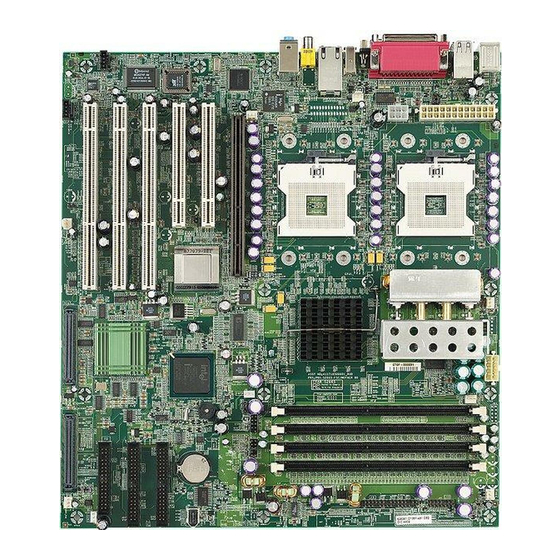
Chapter 2: Board Installation Installation You are now ready to install your motherboard. The mounting hole pattern of the Thunder i7505 S2665 matches the EEB V3.0 specification. Before continuing with installation, confirm that your chassis supports a standard EEB V3.0 motherboard. - Page 7 2.0 – Board The following is an image of the S2665. This picture is representative of the latest board revision available at the time of publishing. The board you receive may or may not look exactly like the above picture. The following page includes details on the vital components of this motherboard.
-
Page 8: Board Parts, Jumpers And Connectors
2.1 – Board Parts, Jumpers and Connectors This diagram is representative of the latest board revision available at the time of publishing. The board you receive may not look exactly like the above diagram. Jumper Legend Jumper OFF without jumper cover Jumper ON with jumper cover To indicate where the location of pin-1... -
Page 9: Jumper And Connector Settings
2.2 – Jumper and Connector Settings Jumper / Function Settings Connector AUX Audio Connector Enable/Disable Onboard Intel Open: Enable (Default) 82540EM GbE NIC Close: Disable Fan Connector Close Pin-1 and Pin-2 (Default) Disable PS/2 devices’ ACPI wake up function PS/2 ACPI Jumper Close Pin-2 and Pin-3 Enable PS/2 devices’... - Page 10 2.3 – AUX Audio Connect or (J8) and CD Audio Connector (J16) J 8 (AUX Audio connector) Connects to internal audio sources such as TV tuner, MPEG, or other similar cards J16 (CD Audio connector) Connects to a CD-ROM drive via an optional CD audio cable 2.4 –...
- Page 11 2.6 – PS/2 ACPI Jumper (J12) pin-3 CLOSE Pins 1 and 2 (Default) To disable PS/2 devices’ ACPI wake up function pin-3 CLOSE Pins 2 and 3 To enable PS/2 devices’ ACPI wake up function 2.7 – Rear Panel USB ACPI Jumper (J14) pin-3 CLOSE Pins 1 and 2 (Default) To disable rear panel USB devices’...
- Page 12 2.9 – Disable Slot-B and Slot-C PCI-X Capability Jumper (J31) OPEN (Default) To enable PCI-X capability on Slot-B and Slot-C CLOSE To disable PCI - X capability on Slot-B and Slot-C Onboard SCSI chip PCI-X capability will be disabled due to sharing of the same bus 2.10–...
- Page 13 2.12 – IEEE 1394 Connector (J66) Connects to a 1394 device via an optional 1394 cable 2.13 – LCD Connector (J69) Connects to a LCD display via an optional cable 2.14 – Front Panel Audio Connector (J71) Signal Signal Description Description Micro input Analog GND...
- Page 14 Pin-1 Intrusion cable detection (low asserted) Pin-2 Intrusion detection (low asserted) Pin-3 2.16 – Front Panel USB Header (J73) Signal Signal Description Description Channel E Channel F Data negative Data negative Channel E Channel F Data positive Data positive connected http://www.TYAN.com...
-
Page 15: Scsi Raid Pci Slot-C
2.17 – Front Panel Connector (J74) Signal Description Pin # Pin # Signal Description Sleep LED “ — “ Speaker “— “ Sleep LED “ + “ Power LED “ + “ Speaker “+ “ Power LED “ + “ Message LED “+ “... -
Page 16: Mounting The Motherboard
2.20 – Mounting the Motherboard Before installing your motherboard, make sure your chassis has the necessary motherboard support studs installed. These studs are usually manufacturer pre-installed, metal and are gold in color. If you are unsure of stud placement, lay the motherboard inside the chassis and align the studs. - Page 17 Make sure that the memory you have is compatible with the motherboard as well as the processor. For example, DDR200 and DDR266 memory modules can be used for FSB=400MHz Intel Xeon processor but only DDR266 memory modules can be used for FSB=533MHz Intel Xeon processor.
-
Page 18: Installing The Processor And Heatsink
2.22 – Installing the Processor(s) and Heatsink(s) Your Thunder i7505 S2665 supports the latest processor technologies from Intel. Check the following page on TYAN’s website http://www.tyan.com for latest processor support: The following diagrams will detail how to install your processor(s): Only identical CPUs can be used. - Page 19 The following diagram will illustrate how to install the most common heatsinks: a. Align the heatsink mounting bracket to the holes around the processor socket b. Insert Black securing peg into bracket holes c. Insert White locking peg into Black securing peg d.
-
Page 20: Installing Add -In Cards
Finishing Installing the Heatsink After you finish installing the heatsink onto the processor and socket, attach the end wire of the fan (which should already be attached to the heatsi nk) to the motherboard. The following diagram illustrates how to connect fans onto the motherboard. After you have finished installing all the fans you can connect your drives (hard drives, CD -ROM drives, etc.) to your motherboard. -
Page 21: Connecting External Devices
2.24 – Connecting External Devices The following diagrams will detail the rear port stack for this S2665 motherboard: a. Audio Port Line In Jack Connects to external devices for playback or recording Line Out Jack Connects to headphone or speakers (Amplifier integrated) Microphone In Jack Connects to an external microphone... -
Page 22: Installing The Power Supply
2.25– Installing the Power Supply There are three power connectors on your Thunder i7505 S2665. By default, the Thunder i7505 S2665 requires that you have an EPS12V power supply that has a 24 -pin and an 8-pin power connector. The extra 6-pin AUX power connector is recommended if you plan on using an AGP Pro video card. -
Page 23: Attaching Ide And Floppy Drive Cables
2.26 – Attaching IDE and Floppy Drive Cables Attaching IDE drive cabling is simple. These cables are “keyed” to only allow them to be connected in the correct manner. Tyan motherboards have two on-board IDE channels, each supporting two drives. The black connector designates the Primary channel, while the white connector designates the Secondary channel. -
Page 24: Finishing Up
2.27 – Finishing Up Congratulations on making it this far! You’re finished setting up the hardware aspect of your computer. Before closing up your chassis, make sure that all cables and wires are connected properly, especially IDE cables and jumpers. You may have difficulty powering on your system if the motherboard jumpers are not set correctly. -
Page 25: Chapter 3:Bios
Chapter 3: BIOS 3.0 – BIOS Setup Utility With the BIOS setup utility, you can modify BIOS settings and control the special features of your computer. The setup utility uses a number of menus for making changes and turning the special features on or off. -
Page 26: Bios Menu Bar
3.1 – BIOS Menu Bar The menu bar at the top of the windows lists these selections: Main To configure basic sys tem setups Advanced To configure the chipset features Security To configure user and supervisor passwords Power To configure power management features Boot To configure system boot order Exit... -
Page 27: Bios Main Menu
3.3 – BIOS Main Menu BIOS Setup Utility Main Advanced Security Power Boot Exit Item Specific Help BIOS Version 1.00.xx <Tab>, <Shift-Tab>, or 4Enable ACPI [Yes] <Enter> selects field 4Installed OS [Win2000/XP] 4Reset Configur ation Data [Yes] System Time [12:59:59] System Date [11/30/2002] System Information... -
Page 28: Bios Advanced Menu
3.4 – BIOS Advanced Menu BIOS Setup Utility Main Advanced Security Power Boot Exit Item Specific Help 4BIOS Event Log and Hardware Monitor 4Processors <Tab>, <Shift-Tab>, or 4Chipset <Enter> selects field 4Floppy Disk Drive 4IDE Devices 4Integrated SCSI Controller 4Integrated Network Controller 4Integrated USB 4I/O Device Configuration 4Integrated Audio... - Page 29 3.4.4 – IDE Devices Sub -Menu Feature Option Description Primary/Secondary Master Auto Auto - To determine the IDE drive type User by system BIOS ATAPI Removable User - To set IDE drive type by user CD-ROM ATAPI Removable - Read-and-write a None media (e.g., LS120, USB floppy, USB Primary/Secondary Slave...
- Page 30 3.4.6 – Integrated SCSI / Network / USB / Audio /1394 Controller Sub -Menu Feature Option Description Integrated PCI Device Enabled This setting determines whether the Disabled integrated PCI device is activated. Option ROM Scan Enabled This setting determines whether the Disabled option ROM of the integrated PCI device is loaded during system BIOS...
-
Page 31: Bios Security Menu
3.5 – BIOS Security Menu BIOS Setup Utility Main Advanced Security Power Boot Exit Item Specific Help 4Set User Password 4Clear All Passwords <Tab>, <Shift-Tab>, or 4Clear Supervisor Password <Enter> selects field 4Clear User Password F1 Help Select Item -/+ Change Values F9 Setup Defaults 4Sub- Menu F10 Save and Exi t ESC Exit... -
Page 32: Bios Boot Menu
3.7 – BIOS Boot Menu BIOS Setup Utility Main Advanced Security Power Boot Exit Item Specific Help 4Quick Boot Mode 4Display Option ROM Message <Tab>, <Shift-Tab>, or 4Default Primary Video Adapter <Enter> selects field 4Boot Device Priority F1 Help Select Item -/+ Change Values F9 Setup Defaults 4Sub- Menu F10 Save and Exit... -
Page 33: Bios Exit Menu
3.8 – BIOS Exit Menu BIOS Setup Utility Main Advanced Security Power Boot Exit Item Specific Help 4Exit Saving Changes 4Exit Discarding Changes <Tab>, <Shift-Tab>, or 4Load Setup Defaults <Enter> selects field 4Discard Changes 4Save Changes F1 Help Select Item -/+ Change Values F9 Setup Defaults 4Sub- Menu F10 Save and Exit... -
Page 34: Chapter 4: Diagnostics
Chapter 4: Diagnostics Note: if you experience problems with setting up your system, always check the following things in the following order: CPU, Memory, Video By checking these items, you will most likely find out what the problem migh t have been when setting up your system. -
Page 35: Appendix I: Glossary
Appendix I: Glossary ACPI (Advanced Configuration and Power Interface): a power management specification that allows the operating system to control the amount of power distributed to the computer’s devices. Devices not in use can be turned off, reducing unnecessary power expenditure. AGP (Accelerated Graphics Port): a PCI-based interface which was designed specifically for demands of 3D graphics applications. - Page 36 Closed and open jumpers: jumpers and jumper pins are active when they are “on” or “closed”, and inactive when they are “off” or “open”. CMOS (Complementary Metal-Oxide Semiconductors): chips that hold the basic startup information for the BIOS. COM port: another name for the serial port, which is called as such because it transmits the eight bits of a byte of data along one wire, and receives data on another single wire (that is, the data is transmitted in serial form, one bit after another).
- Page 37 IDE (Integrated Device/Drive Electronics): a simple, self-contained HDD interface. It can handle drives up to 8.4 GB in size. Almost all IDEs sold now are in fact Enhanced IDEs (EIDEs), with maximum capacity determined by the hardware controller. IDE INT (IDE Interrupt): a hardware interrupt signal that goes to the IDE. I/O (Input/Output): the conne ction between your computer and another piece of hardware (mouse, keyboard, etc.) IRQ (Interrupt Request): an electronic request that runs from a hardware device to the CPU.
- Page 38 RAM (Random Access Memory): technically refers to a type of memory where any byte can be accessed without touching the adjacent data and is often referred to the system’s main memory. This memory is available to any program running on the computer. ROM (Read-Only Memory): a storage chip which contains the BIOS;...
-
Page 39: Technical Support
Technical Support If a problem arises with your system, you should turn to your dealer for help fi rst. Your system has most likely been configured by them, and they should have the best idea of what hardware and software your system contains. Furthermore, if you purchased your system from a dealer near you, you can bring your system to them to have it serviced instead of attempting to do so yourself (which can have expensive consequences). -
Page 40: Http://Www.tyan.com
Notice for the USA Compliance Information Statement (Declaration of Conformity Procedure) DoC FCC Part 15: This device complies with part 15 of the FCC Rule s Operation is subject to the following conditions: This device may not cause harmful interference, and This device must accept any interference received including interference that may cause undesired operation.
Need help?
Do you have a question about the Thunder i7505 and is the answer not in the manual?
Questions and answers