Table of Contents
Advertisement
Quick Links
Declaration of Conformity
According to 47 CFR, Parts 2 and 15 of the FCC Rules
The following designated product:
EQUIPMENT: MAINBOARD
MODEL NO.: 7NIF2
is a Class B digital device that complies with 47 CFR Parts 2 and 15 of the FCC
Rules. Operation is subject to the following two conditions:
1. This device may not cause harmful interference.
2. This device must accept any interference received, including interference that
may cause undesired operation.
This declaration is given to the manufacturer:
CHAINTECH-EXCEL COMPUTER INC.
4427 Enterprise St. Fremont, CA 94538, U.S.A.
http://www.chaintech-excel.com
Chaintech President: Simon Ho
Signature:
AMD®
Motherboard
7NIF2
AMD® Socket A
NVIDIA nForce 2 IGP+ MCP
u-ATX Motherboard
User's Manual
Version 2.0
Advertisement
Table of Contents

Related Manuals for AMD 7NIF2


Summary of Contents for AMD 7NIF2
- Page 1 According to 47 CFR, Parts 2 and 15 of the FCC Rules The following designated product: 7NIF2 EQUIPMENT: MAINBOARD MODEL NO.: 7NIF2 AMD® Socket A NVIDIA nForce 2 IGP+ MCP is a Class B digital device that complies with 47 CFR Parts 2 and 15 of the FCC Rules.
-
Page 2: Table Of Contents
1-2 Package Contents.....................2 Part 15 of the FCC Rules. These limits are designed to provide reasonable protection against harmful interference 1-3 7NIF2 Motherboard Diagram................3 in a residential installation. This equipment generates, uses, and can radiate radio frequency energy. If this 1-4 7NIF2 Motherboard Layout................4... -
Page 3: Chapter 1 Introduction
ITE 8712 LPC I/O with system monitors hardware Processor Two UARTs support serial ports and IR function (up to 115.2Kbps) for HPSIR and Supports AMD Socket A Duron / Athlon / Athlon XP processors ASKIR System Clock supports 200 / 266 / 333 MHz Front Side Bus... -
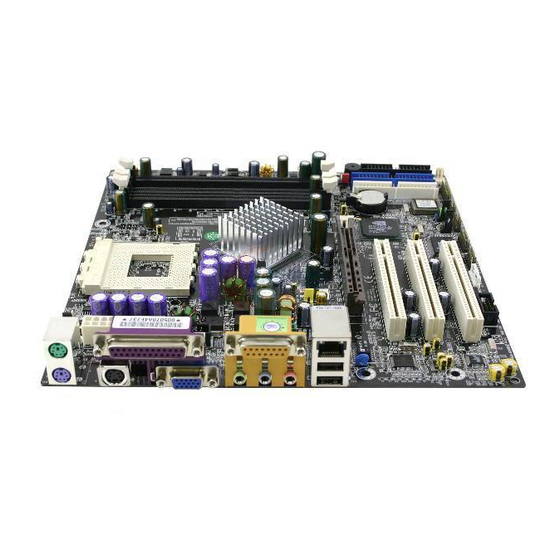
Page 4: 7Nif2 Motherboard Diagram
Chapter 1 Chapter 1 1-3 7NIF2 Motherboard Diagram 1-4 7NIF2 Motherboard Layout... -
Page 5: Chapter 2 Hardware Setup
1.6V 64KB 0.18 Installing an AMD® approved heat sink with cooling fan is necessary for proper heat dissipation from your CPU. Failing to install these items may result in overheating and possible burnout of your CPU. In order to boot up with a newly installed CPU, AC Power must be... -
Page 6: Main Memory Configuration
1400 1400MHz 10.5 1.75V 256KB 0.18 Location 64 MB 128 MB 256 MB 512 MB 1.0 GB DDR 1 AMD Athlon XP CPU (Palomino/Thoroughbred) DDR 2 DDR 3 Micron Model CPU Speed Multiplier Vcore Frequency Cache process To install your DDR Modules please follow the following steps:... -
Page 7: Connector And Jumper Reference Chart
Chapter 2 Chapter 2 2-4 Connector and Jumper Reference Chart 2-5 Connector and Jumper Settings Connectors are used to link the system board with other parts of the system, Jump Connector Function Page including the power supply, the keyboard, and the various controllers on the front panel of the system case. -
Page 8: Fd1 Floppy Connector
Chapter 2 Chapter 2 Power-On By Modem: IDE 1/2 (IDE Hard-Disk Connector) While in Soft-Off state, if an external modem ring-up signal occurs, the system wakes up and can be remotely accessed. You may enable this function in BIOS's Power Management Setup menu. (See section 3). Blinking LED in Suspend Mode: While in Suspend mode, the LED light on the front panel of your computer will flash. -
Page 9: Fan
Chapter 2 Chapter 2 JP5 (Keyboard Power On Function Jumper): FAN 4 (North Bridge Cooling Fan Power) Definition 1-2 Disable (default) Enable This board can be turned on by the PS / 2 keyboard (hot key). To use this function, This connector is for the north bridge-cooling fan. -
Page 10: Jp6A /B Disable/Enable Usb 2/3,4/5 Device Power On Jumper
Chapter 2 Chapter 2 JP6A/B (Enable/Disable USB 2/3, 4/5 Device Power ON Jumper) JP25 (Setup CPU FSB. Freq. Jumper) Definition Definition 1-2 Disable (default) 133/166 MHz (default) Enable 100 MHz A USB keyboard hot key or a USB mouse click can turn on this motherboard. To This cap setups up the CPU Ext. -
Page 11: Cn2 /2A Cd-Rom Audio-In Connector
Chapter 2 Chapter 2 the system back to Full-On. Pushing the button while in Full-On mode for more CN3 (Auxiliary Audio-in Connector): than [4 seconds] will switch the system completely off. See Over-ride Power Button Operation diagram. 2. P-LED (Power LED Connector): The power indicator LED shows the system's power status. -
Page 12: Cn5 Wake On Lan Connector
Chapter 2 Chapter 2 CN5 [WOL (Wake-on-LAN) Connector]: CN7 (Smart Card Reader Connector): Enable the Wake Up On LAN selection in BIOS's Power Management Setup Menu to use this function. The capability to remotely manage PCs on a network is a This connector must be connected to a Smart card reader, which allows you to significant factor in reducing administrative and ownership costs. -
Page 13: Cn17 Blue Led Connector (5V)
Chapter 2 Chapter 2 CN17 (Blue LED Connector): CN24 (Front Audio Connector): These features work entirely the same as the power indicator LED, both shows the This connector give you the option of a front panel audio jack cable ext. to be plug system’s power status. -
Page 14: Chapter 3 Bios Setup Program
Chapter 2 Chapter 3 Chapter 3 BIOS Setup Program COM 2 (Serial port / COM Headers) Phoenix-Award BIOS ROM has a built-in setup program that allows users to modify the basic system configuration. This information is stored in CMOS RAM so that it can retain the setup information, even when the power is turned off. -
Page 15: Standard Cmos Features
Chapter 3 Chapter 3 3-2 Advanced BIOS Features 3-1 Standard CMOS Features By choosing the Advanced BIOS Features option from the CMOS Setup Utility menu The Standard CMOS Features allows users to configure system components such as (Figure 3-1), the screen below is displayed. This sample screen contains the hard disk drive, floppy disk drive and video display as well as date, time and boot-up manufacturer's default values for the motherboard. - Page 16 Chapter 3 Chapter 3 completes. BIOS will search these drives for an operating system. Controller). Due to compliance to PC2001 design guide, the system is able to run in APIC mode. Enabling APIC mode will expand available IRQs resources for the Swap Floppy Drive system.
-
Page 17: Advanced Chipset Features
Chapter 3 Chapter 3 CPU Interface 3-3 Advanced Chipset Features This option allows you to determine how your CPU interface performs. Available By choosing the [Advanced Chipset Features] option from the CMOS Setup Utility options are: [Optimal] and [Aggressive] there details are as follows: menu (Figure 3-1), the screen below is displayed. -
Page 18: Integrated Peripherals
Chapter 3 Chapter 3 which is not in use, will be available for the system. For example, if 16MB is allotted 3-4 Integrated Peripherals to the AGP card and the card only needs 8MB, the remaining 8MB will be available This section provides information on setting peripheral devices. - Page 19 Chapter 3 Chapter 3 5. IDE HDD Block Mode: parallel port. Block mode is also called block transfer, multiple commands, or multiple sector 6. Parallel Port Mode: read/write. If your IDE hard drive supports block mode, select Enabled to Select an operating mode for the onboard parallel (printer) port. Select SPP unless auto-detect the optimal number of block read/writes per sector the drive can support.
-
Page 20: Power Management Setup
Chapter 3 Chapter 3 1. Blank Screen - BIOS will only blank the monitor's screen. The electricity saved in 3-5 Power Management Setup this mode is negligible and this function is only used as a screen saver to prevent This section provides information on the Green PC power management functions. By screen damage while the screen is on but not in use. -
Page 21: Pnp/Pci Configurations
Chapter 3 Chapter 3 signal and wake up the system from soft off and green mode. You should connect the 3-6 PNP/PCI Configurations modem to the COM port and call your PC to power on. This section provides IRQ and DMA setting information. By choosing the PNP/PCI 3. -
Page 22: Pc Health Status
Chapter 3 Chapter 3 3-7 PC Health Status 3-8 Frequency/Voltage Control By choosing the PC Health Status option from the CMOS Setup Utility menu (Figure By choosing the Frequency/Voltage Control option from the CMOS Setup Utility 3-1), the screen below is displayed. This field shows you the current CPU menu (Figure 3-1), the screen below is displayed. -
Page 23: Load Fail-Safe Defaults
Chapter 3 Chapter 3 3-9 Load Fail-Safe Defaults 3-12 Save and Exit Setup Load Fail-Safe Defaults loads the default BIOS values directly from the CMOS Setup If you select this and type [Y] (for Yes) followed by the [Enter] key, the values Utility menu (Figure3-1). -
Page 24: Chapter 4 Driver Setup
Chapter 4 Chapter 4 3. Please, click [OK] to continue. Chapter 4 DRIVER Setup Please insert the nVidia Series driver CD into the CD-ROM. 4. To restart you computer now, select [Yes, I want to restart my computer now.] then Please Click [OK] to restart you computer. If you do not want to restart your computer select [No, I will restart my computer later.] then click [OK] to continue. -
Page 25: Video Application
Chapter 4 Chapter 4 3. To restart you computer now, select [Yes, I want to restart my computer now.] then Please Click [OK] to restart you computer. If you do not want to restart your computer select [No, I will restart my computer later.] then click [OK] to continue. -
Page 26: Audio Driver
Chapter 4 Chapter 4 3. Please, click [Next>] to continue install the C-Media Audio driver. 4-3 Audio driver 4. Please, click [Next>] to continue install the C-Media Audio driver. 1. Please, select [Audio Drive] to begin installation. 2. Please, click [NEXT>] to start installation. -
Page 27: Usb 2.0 Driver Setup
Chapter 4 Chapter 4 5. Please, click [Next>] to continue install the C-Media Audio driver. 7. To restart you computer now, select [Yes, I want to restart my computer now.] then Please Click [OK] to restart you computer. If you do not want to restart your computer select [No, I will restart my computer later.] then click [OK] to continue. -
Page 28: Chapter 5 How To Update Your Bios
Chapter 5 Chapter 5 `0`(zero) and o (letter `O`)). Then run the flash utility. Chapter 5 How to update your BIOS? On the screen the program will ask for the [File Name to Program]. Type in the Updating BIOS may result an unstable system. All the data of the old BIOS exact name of the BIOS update binary file, including the *.BIN, and press will be replaced by the new BIOS. - Page 29 Note How To Contact CHAINTECH How To Contact CHAINTECH NOTE Please do not hesitate to contact us if you have any problem about our products. Any opinion will be appreciated. For Asia, Africa, Australia and Pacific Island: For America: All rights are reserved for the products and corporate names/logos that CHAINTECH COMPUTER CO., LTD CHAINTECH-EXCEL COMPUTER INC.
Need help?
Do you have a question about the 7NIF2 and is the answer not in the manual?
Questions and answers