Enterasys VH-2402S User Manual
Vertical horizon fast ethernet switch
Hide thumbs
Also See for VH-2402S:
- Release notes (8 pages) ,
- Management manual (110 pages) ,
- Web management manual (68 pages)
Table of Contents
Advertisement
Advertisement
Table of Contents

Subscribe to Our Youtube Channel
Related Manuals for Enterasys VH-2402S


Summary of Contents for Enterasys VH-2402S
- Page 1 Vertical Horizon VH-2402S FAST ETHERNET SWITCH USER GUIDE 9033644...
- Page 3 NOTICE Enterasys Networks reserves the right to make changes in specifications and other information contained in this document without prior notice. The reader should in all cases consult Enterasys Networks to determine whether any such changes have been made.
-
Page 4: Fcc Notice
SAFETY INFORMATION CLASS 1 LASER TRANSCEIVERS The VH-2402S 24-port switch uses Class 1 Laser transceivers. Read the following safety information before installing or operating these modules. Class 1 laser transceivers use an optical feedback loop to maintain Class 1 operation limits. This control loop eliminates the need for maintenance checks or adjustments. - Page 5 Notice • 21 CFR 1040.10 and 1040.11 U.S. Department of Health and Human Services (FDA). • IEC Publication 825 (International Electrotechnical Commission). • CENELEC EN 60825 (European Committee for Electrotechnical Standardization). • When operating within their performance limitations, laser transceiver output meets the Class 1 accessible emission limit of all three standards.
- Page 6 Notice SAFETY INFORMATION WICHTIGE SICHERHEITSHINWEISE (GERMANY) Bitte lesen Sie diese Hinweise sorgfältig durch. Heben Sie diese Anleitung für den späteren Gebrauch auf. Vor jedem Reinigen ist das Gerät vom Stromnetz zu trennen. Verwenden Sie keine Flüssigoder Aerosolreiniger. Am besten eignet sich ein angefeuchtetes Tuch zur Reinigung. Die Netzanschlu ßsteckdose soll nahe dem Gerät angebracht und leicht zugänglich sein.
- Page 7 BEFORE OPENING OR UTILIZING THE ENCLOSED PRODUCT, CAREFULLY READ THIS LICENSE AGREEMENT. This document is an agreement (“Agreement”) between You, the end user, and Enterasys Networks, Inc. (“Enterasys”) that sets forth your rights and obligations with respect to the Enterasys software program (“Program”) in the package.
- Page 8 Notice UNITED STATES GOVERNMENT RESTRICTED RIGHTS. The enclosed Product (i) was developed solely at private expense; (ii) contains “restricted computer software” submitted with restricted rights in accordance with section 52.227-19 (a) through (d) of the Commercial Computer Software-Restricted Rights Clause and its successors, and (iii) in all respects is proprietary data belonging to Enterasys and/or its suppliers.
-
Page 9: Declaration Of Conformity
Notice DECLARATION OF CONFORMITY Application of Council Directive(s): 89/336/EEC 73/23/EEC Manufacturer’s Name: Enterasys Networks, Inc. Manufacturer’s Address: 35 Industrial Way PO Box 5005 Rochester, NH 03867 European Representative Name: Mr. J. Simms European Representative Address: Enterasys Networks Limited Nexus House, Newbury Business Park... - Page 10 Notice 9033644 viii...
-
Page 11: Table Of Contents
TABLE OF CONTENTS PREFACE ............XI Purpose. - Page 12 APPENDIX B. FLOW CONTROL ........35 APPENDIX C. ACRONYMS & ABBREVIATIONS ..... . 37 INDEX x Table of Contents VH-2402S...
-
Page 13: Preface
PREFACE Purpose This guide provides information about the features and applications of the Enterasys Networks Vertical Horizon VH-2402S stackable switch system. Audience This guide is intended for Ethernet Local Area Network (LAN) administrators and Management Information Systems (MIS) personnel with the following background: •... -
Page 14: Other Conventions
Appendix C. Acronyms and Abbreviations: Provides definitions for a list of common acronyms and abbreviations used within the installation guide and the networking industry. xii Preface VH-2402S... -
Page 15: Product Overview
Application Example Description This installation guide describes Enterasys Networks’ Vertical Horizon VH-2402S Fast Ethernet switch. The switch provides 24 10Base-T/100Base-TX ports, plus two slots for optional slide-in 100Base-FX, 1000Base-SX or 1000Base-LX modules. One of these slots can also be used for an optional Stacking Module that allows you to attach up to seven switches to a 5 Gbps high-speed backplane. -
Page 16: Features
Microsoft’s Internet Explorer. In addition, the console port allows out-of- band management using a PC, terminal, or modem connection. The VH-2402S switch is desktop or rack-mountable. LEDs on the front panel provide information about the operating status of the switch. The back panel contains the power connector, redundant power connector, and three slots for the optional modules. - Page 17 • Switch Architecture: - 3 controllers with 8 10/100 ports - IEEE 802.3u auto-negotiation of half/full-duplex operation on all RJ-45 ports - Up to 7 switch units can be stacked together, supporting up to 182 connections - 128 KB packet buffering for 10/100 ports, 2 MB packet buffering for 1000 ports - Store-and-forward switching - 8K address forwarding table...
-
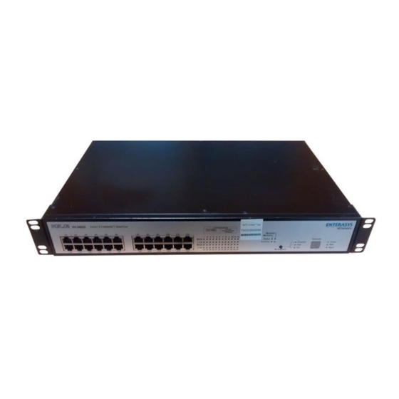
Page 18: Front Panel
Front Panel Figure 1-1 shows the front panel of the Enterasys Networks Vertical Horizon VH-2402S. Table 1-1 defines the VH-2402S front panel components. Figure 1-1. VH-2402S Front Panel Table 1-1. Front Panel Components Name Function Power LED Lights steady green to indicate power is supplied to the switch. -
Page 19: Optional Modules
Optional Modules Figure 1-2 shows the optional modules available for the Enterasys Networks Vertical Horizon VH-2402S. Table 1-2 defines the optional module components. Figure 1-2. Optional Modules Table 1-2. Optional Module Components Module Components 100Base-FX (MMF) Ports: Two multi-mode fiber ports using SC connectors for uplink. -
Page 20: Rear Panel
Console port: Male DB-9 connector configured as a null modem connection for serial out-of-band management using the console menus. Rear Panel Figure 1-3 shows the VH-2402S rear panel and Table 1-3 defines the rear panel components. Figure 1-3. VH-2402S Rear Panel Table 1-3. Rear Panel Components... -
Page 21: Feature Summaries
To minimize the possibility of dropping frames on congested ports, the VH-2402S switch provides 128 KB of frame buffering per port. This buffer space is used to queue packets for transmission on congested networks. This is an additional advantage over cut-through switching technology, which drops packets immediately when experiencing collisions. -
Page 22: Software Download
You can connect directly to the RS-232 port on the Management Module, or make a connection via a modem. See the Management Guide for information on managing the VH-2402S switch (or stack) via the serial console. • Telnet, in-band (over Ethernet) The switch supports management through a Telnet connection using the TCP/IP protocols. -
Page 23: Rmon
SNMP management station. The VH-2402S supports four of the nine groups of RMON defined for Ethernet networks on a per segment basis. Specifically, these are: •... -
Page 24: Auto-Negotiation
It is not required that the network device being connected to the switch supports auto- negotiation as the VH-2402S switch automatically adjusts to the network device’s communication settings. Auto-negotiation is configurable using the console interface menus, the on-board Web agent, or via SNMP. -
Page 25: Flow Control
The VH-2402S allows up to four ports of the same media type to be joined together as a trunk. Up to four port trunks on a single switch, or 12 for an entire stack, can be configured. -
Page 26: Factory Defaults
100 - 10Mbps ports Port Priority Spanning Tree Protocol Enabled System Configuration BootP Enable Disabled Password <none> Screen Timeout 10 min Send Authentication Fail Traps Enabled SNMP Community Name public, private Terminal Baud Rate Auto User Names admin, guest 12 Product Overview VH-2402S... - Page 27 Parameter Default Value Virtual LANs Acceptable VLAN Frame Type Configurable PVID Tagging GVRP Disabled Untagged VLAN Group Assignment VLAN Ingress Filtering False VLAN Learning 9033644 Product Overview 13...
-
Page 28: Application Examples
The VH-2402S switch is ideal for meeting the needs of today’s high performance networks. The switch’s low cost and high port count makes it attractive and affordable for dedicated 10/100Mbps connections to the desktop. -
Page 29: Client/Server Network Application
Client/Server Network Application To improve workstation performance in a client/server environment, the VH-2402S switch can be configured to provide 200 Mbps full duplex Fast Ethernet connections to servers by connecting each to a dedicated switch port (Figure 1-4). Users can be accommodated through connections to hubs, both at 10Mbps and 100Mbps speeds, through 10Mbps switches with 100Mbps uplinks, or through direct connections. -
Page 30: Local Backbone Application
Local Backbone Application The VH-2402S switch can be used in a local backbone application, connecting network segments together and providing file-server access (Figure 1-5). Workgroup hubs are provided with a single connection to the switch while servers are put on dedicated 100 Mbps ports. Routers and other networking devices can connect off of the switched backbone as well. -
Page 31: Installation
2. INSTALLATION Inspecting Your Shipment When you receive the shipment of your switch, check the package contents and make sure you have the following items: • VH-2402S stackable switch • Mounting ears and mounting screws • Four rubber feet •... -
Page 32: Mounting The Switch Or Stack On A Table Or Shelf
• Environmental Install the VH-2402S switch in a dry area, with adequate air circulation. Avoid placing the switch in direct sunlight or near other heat sources, such as hot-air vents. For temperature and humidity specifications, see Appendix A, “Technical Specifications.”... -
Page 33: Mounting The Switch In A Rack
Mounting the Switch in a Rack The switch ships with two (2) multi-position mounting ears and four (4) mounting screws. The mounting screws are used to attach the mounting ears to the switch. Once the ears are attached to the switch, you will need to provide appropriate screws to mount the switch in a rack. -
Page 34: Connecting Switches To The Stack's Backplane
UP port on the last switch. Figure 2-2. Connecting Switches to the Stack’s Backplane Stacking Module and Interconnect Cables Table 2-1 provides information for the Stacking Module and interconnect cables available for the VH-2402S. Table 2-1. Stacking Module and Interconnect Cables Part Number Functions... -
Page 35: Installing An Optional Module Into The Switch
Installing an Optional Module into the Switch Optional modules are available for media expansion, stacking and management. These modules can be installed into the modular slots on the rear panel of the switch. The Management Module must be installed in the upper slot, and the Stacking Module in the lower-left slot. The media extension modules can be installed in either of the two lower slots. -
Page 36: Connecting A Terminal To The Console Port
This cable is shielded to comply with emissions regulations and requirements. Console Port (Out-of-Band) Connections To connect the VH-2402S console port to a terminal, do the following: Connect a VT100 compatible terminal or a PC running a terminal emulation program to the console port (Figure 2-4). Use the null-... -
Page 37: Remote Management Via The Console Port
Connect the other end of the interface cable to a terminal (in some instances, an adapter may be required to make this connection). From your terminal, start the terminal emulation program. Configure the terminal to the following communication settings: VT100 emulation, 19200 baud, no parity, 8 data bits, 1 stop bit, no flow control, ASCII character set. -
Page 38: Management Module
Management Module Table 2-2 provides information for the Management Module available for the VH-2402S. Table 2-2. Management Module Part Number Functions Description VH-SMGMT RMON/SNMP/ SNMP agent module used to manage the switch (or Web Manage- attached stack). Includes RS-232 serial port for ment console connection. -
Page 39: Powering The Switch
Powering the Switch To supply power to the switch, connect the power cord to the switch and to a grounded three-prong wall outlet (Figure 2-5). See Appendix A, “Technical Specifications” on page 29 for more information regarding specific international power cord requirements. Figure 2-5. -
Page 40: Network Cable Requirements
Network Cable Requirements Copper Table 2-3 specifies the cable types and length constraints for the various copper interfaces on the VH-2402S. Table 2-3. Copper Cable Specifications Interface Type Cable Requirement Maximum Length 10Base-T Category 3 or 5 Unshielded Twisted 100m (328 ft.) -
Page 41: 10Base-T/100Base-Tx Ports
Table 2-6 specifies the fiber types, bandwidth requirements, and length constraints for the Gigabit Ethernet long-wavelength fiber interface on the fiber optic media module. Table 2-6. 1000Base-LX Fiber Specifications Fiber Diameter Modal Bandwidth @ 1300 nm Range (microns) 62.5 µm MMF 500 MHz/km 2-550 Meters 50 µm MMF... -
Page 42: 100Base-Fx/1000Base-Sx/Lx Fiber Ports
The 100Base-FX and 1000Base-SX/LX fiber ports use SC connectors. Figure 2-7 shows an SC fiber connector being inserted into a fiber port on the VH-2402S. Figure 2-7. Inserting an SC Fiber Connector into a Fiber Port The fiber uplink modules employed (Table 2-7) support multi-mode 62.5/ 125µm fiber and single-mode 10/125µm fiber. -
Page 43: Appendix A. Technical Specifications
APPENDIX A. TECHNICAL SPECIFICATIONS General Standards Compliance IEEE 802.1D Transparent Bridging Specifications (ISO/IEC 10038) IEEE 802.1p Traffic Class Expediting and Dynamic Multicast Filtering IEEE 802.1Q Virtual Bridged Local Area Networks IEEE 802.2 Local Area Networks, Logical Link Control (LLC) IEEE 802.3 CSMA/CD 9 (ISO/IEC 8802-3) IEEE 802.3i 10Base-T (ISO/IEC 8802-3, clause 14) IEEE 802.3u 100Base-TX (ISO/IEC 8802-3, clause 25) IEEE 802.3u 100Base-FX... -
Page 44: Electrical Specifications
50-60 Hz Maximum power consumption: 80 VA Physical Specifications Height: 2.5 in. (6.4 cm) Length: 11.2 in. (28.5 cm) Width: 17.3 in. (44 cm mountable in a standard 19 in. rack) Weight: 10.63 lb. (4.82 kg) 30 Technical Specifications VH-2402S... -
Page 45: Port Specifications
Port Specifications Console Port Table A-1 shows the console port pin assignments. Table A-1. RS-232 Console Port Pin Assignments Signal Name Ground 10Base-T and 100Base-TX Ports Table A-2 shows the 10Base-T/100Base-TX pinouts. These ports are wired MDI-X. All undefined pins are not used. Table A-2. -
Page 46: Mdi/Mdi-X Crossover Cable Wiring
Figure A-1. External Crossover Cable Wiring Power Cord Set Requirements The wide-range input feature of the VH-2402S Ethernet switch permits it to operate from any line voltage between 100 and 240 VAC. The power cord set (appliance coupler, flexible cord, and wall plug) you received with the switch meets the requirements for use in the country where you purchased the switch. -
Page 47: Country-Specific Requirements
Country-Specific Requirements Table A-3 lists the power cord set requirements by country and identifies the accredited agency within that country. Table A-3. Power Cord Set Requirements by Country Country Accredited Agency See Notes * Australia EANSW Austria Belgium CEBC Canada Denmark DEMKO Finland... - Page 48 Japanese Dentori Law. Flexible cord must be Type VCT or VCTF, 3-conductor, 0.75mm conductor size. Wall plug must be a two-pole grounding type with a Japanese Industrial Standard C8303 (15A, 125V) configuration. 34 Technical Specifications VH-2402S...
-
Page 49: Appendix B. Flow Control
Workstation A will resume sending data. Similarly, the back-pressure mechanism forces Workstation A to stop sending packets by inducing collisions on port X. The pause-frame flow-control mechanism supported by the VH-2402S switch conforms with the IEEE 802.3x specification for full-duplex flow control. - Page 50 36 Flow Control VH-2402S...
-
Page 51: Appendix C. Acronyms & Abbreviations
APPENDIX C. ACRONYMS & ABBREVIATIONS Term Definition 10Base-T 10 Mbps twisted-pair Ethernet 100Base-TX 100 Mbps twisted-pair Fast Ethernet 100Base-FX 100 Mbps fiber option Fast Ethernet 1000Base-SX 1000 Mbps fiber option short-wavelength Gigabit Ethernet 1000Base-LX 1000 Mbps fiber option long-wavelength Gigabit Ethernet ANSI American National Standards Institute BootP... - Page 52 Term Definition SNMP Simple Network Management Protocol TCP/IP Transmission Control Protocol/Internet Protocol TFTP Trivial File Transfer Protocol Transmit Data Unshielded Twisted Pair VLAN Virtual LAN 38 Acronyms & Abbreviations VH-2402S...
- Page 53 INDEX 1000Base-LX data rates, 29 cables, 27 DB-9 connector, 8 module defined, 6 default settings, 12 1000Base-SX description of switch, 1 cables, 26 dimensions of switch, 30 module defined, 5 downloading software, 8 100Base-FX modules defined, 5 DTE connection, 22 10Base-T/100Base-TX ports, 27 duplex mode, auto-negotiation of, 10 802.1D, 7...
- Page 54 RMON, 9 mounting ears, 19 RS-232 port mounting the switch cable connection, 22 in a rack, 19 out-of-band management, 8 on a table or shelf, 18 pin assignments, 31 multi-mode fiber, 26, 28 rubber foot pads, 18 2 Index VH-2402S...
- Page 55 safety compliance, 29 TCP/IP protocol, 8 SC ports, 28 Telnet, 8, 23 screws, mounting, 19 terminal connection, 8, 22 SCSI II ports, 6 tests, hardware and software, 25 serial port TFTP download, 8 connecting to, 22 traffic priority, 11 out-of-band management, 8 transmit queues, 35 pin assignments, 31 trunking, 11...
- Page 56 4 Index VH-2402S...
- Page 58 150xxx-102 R01...
Need help?
Do you have a question about the VH-2402S and is the answer not in the manual?
Questions and answers