Table of Contents
Advertisement
Quick Links
Advertisement
Table of Contents

Related Manuals for Planet ICA-HM220W


Summary of Contents for Planet ICA-HM220W
- Page 1 Wireless H.264 Mega-Pixel PT IP Camera ICA-HM220W User’s Manual Version: 1.00...
- Page 2 Copyright Copyright © 2008 by PLANET Technology Corp. All rights reserved. No part of this publication may be reproduced, transmitted, transcribed, stored in a retrieval system, or translated into any language or computer language, in any form or by any means, electronic, mechanical, magnetic, optical, chemical, manual or otherwise, without the prior written permission of PLANET.
- Page 3 Do not dispose of WEEE as unsorted municipal waste and have to collect such WEEE separately. Revision User’s Manual for PLANET Wireless H.264 Mega-Pixel PT IP Camera Model: ICA-HM220W Rev: 1.0 (March. 2010) Part No. EM-ICAHM220W...
-
Page 4: Table Of Contents
Table of Content I ntroduction ........................5 1 .1 O verview ......................5 1 .2 F eatures ......................5 1 .3 P ackage Contents ..................... 6 B asic Setup ......................... 7 2 .1 S ystem Requirements ..................7 2 .2 P hysical Description .................. - Page 5 3 .7.3. E mail ...................... 61 3 .7.4. F TP Configuration ................63 3 .7.5. S D Card Configuration ............... 64 3 .8 S ystem Info ...................... 65 3 .8.1. C amera Information ................65 3 .8.2. D ate / Time Setting ................
-
Page 6: I Ntroduction
I ntroduction Thank you for purchasing the PLANET Wireless H.264 Mega-Pixel PT IP Camera. It is versatile and high image solution of surveillance application IP Camera is also a stand-alone camera system with a built-in processor and web server that provides highest quality video and system performance. -
Page 7: Package Contents
Package Contents 1 1 B IP Camera x 1 Power Adapter x 1 RJ-45 cable x 1 Quick Installation Guide x 1 User’s manual CD x 1 Ceiling Mount Accessories x 1 Antenna x 2 NOTE: 1. If any of the above items are missing, please contact your dealer immediately. 2. -
Page 8: B Asic Setup
B asic Setup This chapter provides details of installing and configuring the PT IP Camera S ystem Requirements 1 2 B The Internet Camera can be monitoring on all of Windows operating system that suggest with system requirment below in order to got better video performance. Network Interface 10/100MBase-TX Ethernet Monitoring System... -
Page 9: P Hysical Description
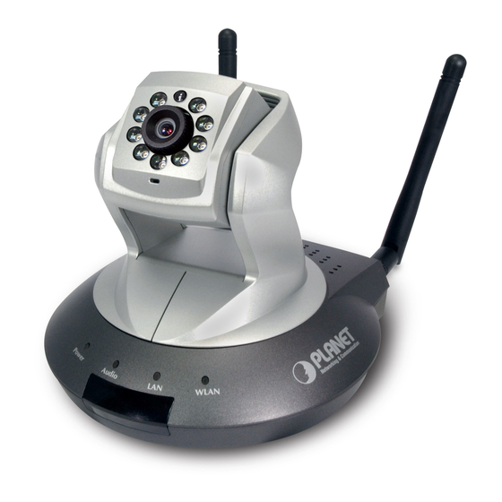
P hysical Description 1 3 B 2.2.1. F ront Panel 2 9 B 1. Focus Ring 4. Infrared LED 5. Microphone 2. LAN LED 6. Audio LED 3. WLAN LED 7. Power LED Focus Ring User could use this ring to adjust focus manually. The LED indicates LAN activity. -
Page 10: R Ear Panel
2.2.2. R ear Panel 3 0 B 1. Audio 5. SD Card Slot Connector 2. LAN 6. WPS Button 3. Antenna Base 7. Power Connector 4. Reset Button Audio-Out allows device to output audio or alerting sound. Audio Connector This is a RJ-45 connector for connections to 10/100 Base-TX Ethernet cabling and built N-Way protocol can detect or negotiate the transmission speed of the network automatically. -
Page 11: B Ottom Panel
2.2.3. B ottom Panel 3 1 B Tripod Connector Tripod Connector: Allows connects to tripod to secure the camera when the camera is not put on a horizontal surface. -
Page 12: H Ardware Installation
H ardware Installation 1 4 B 2.3.1. C amera Physical Installation 3 2 B Please follow the following instructions to set your IP camera up. 1. Unpack the product package and check if anything’s missing. 2. Connect the Ethernet cable to your local area network, and connect the other end to the LAN jack of this IP camera. - Page 13 3. Connect two antennas to the antenna bases, which is located at the back of the IP camera. 4. Place the camera at a secure place, and point the camera to the place you wish to monitor. If you wish to hang the camera on the ceiling or wall, please use the tripod connector (located at the bottom of the camera) to secure the camera.
-
Page 14: L Ocate The Ip Address Of This Ip Camera
2.3.2. L ocate the IP Address of this IP Camera 3 3 B Default IP address of this IP camera is 192.168.0.20. If you wish to assign another IP address to this IP camera, you have to log onto the web configuration interface of the camera first. If the left three fields of the IP address of your computer is not 192.168.0.x, you’ll have to change the IP address of your computer first: 1. - Page 15 2. Double-click Network Connections icon. 3. Right-click Local Area Connection, and click Properties.
- Page 16 4. Select “Internet Protocol (TCP/IP)”, then click Properties.
- Page 17 5. In IP address field, please fill in any IP address begins with 192.168.0, and ends with a value greater than 2 and less than 254 (You can use the following example 192.168.0.239). In Subnet mask field, please fill 255.255.255.0. Please keep all other fields empty, and click OK. If you changed the IP address of this IP camera and you forget it, there’re 2 methods to recover it: a.
-
Page 18: I Nitial Utility Installation
I nitial Utility Installation 1 5 B This chapter shows how to quick set up your IP camera. The Camera is with the default settings. However to help you find the networked camera quickly the admin software can search the cameras in the network that shall help you to configure some basic setting before you started advanced management and monitoring. - Page 19 2. You can change the installation folder of camera setup software here, click Browse to select an existing folder, or you can just click Next to use default installation folder: 3. If you wish to create desktop icon and / or quick launch icon for camera admin software, please check corresponding box, and click Next to continue.
- Page 20 4. You’ll see a brief of all options you selected, click Install to install camera admin software now, or click back to back to previous steps to change settings. 5. When you see this message, the installation of camera admin software is complete. If you wish to launch camera admin software now, keep Launch IP Cam Admin Utility box checked, and click Finish to close installation utility.
- Page 21 6. Please double-click the utility icon on the desktop then you will see the IP camera utility. After the camera admin software is launched, all cameras found on your local area network will be displayed: All camera-related information will be displayed here. If you wish to connect to certain camera by web browser, double-click the camera listed here.
- Page 22 The camera admin software also provides several functions: This camera admin software supports 3 languages: English, Chinese, and Japanese. User can select the language Language oneself wish to use from language dropdown menu located at upper-right corner of camera admin software. Search camera: Click this button to search all cameras on local area network again.
-
Page 23: C Amera Admin Locate Ip Camera
C amera Admin locate IP Camera 1 6 B If you can’t connect to the camera by the instructions given in last chapter, you can use camera admin software to search the camera which is connected to your local area network. The admin software is also capable to locate multiple cameras on your local area network. - Page 24 In Security’ page, user can change the camera’s name and password (user name is always ‘admin’ and cannot be changed). You have to input the same password in both New Password and Confirm Password field, or you’ll be prompted to input new password again. Click OK to save settings or click Cancel to discard changes.
-
Page 25: U Sing Upnp Of Windows Xp Or Vista
U sing UPnP of Windows XP or Vista 1 7 B Universal Plug and Play (UPnP) is a set of computer network protocols. This is to allow device to connect seamlessly and to simplify the implementation of network in the network and corporate environments. - Page 26 The Add or Remove Programs will display on the screen and click Add/Remove Widows Components to continue. The following screen will appear, select Networking Services and click Details to continue...
- Page 27 The Networking Services will display on the screen, select Universal Plug and Play and click OK to continue. Please click Next to continue...
- Page 28 The program will start installing the UPnP automatically. You will see the below pop-up screen, please wait while Setup configures the components. Please click Finish to complete the UPnP installation...
- Page 29 Double-click My Network Places on the desktop, the My Network Places will display on the screen and double-click the UPnP icon with IP camera to view your device in an internet browser.
-
Page 30: W Indows Vista
Network and Sharing Center, and turn on Network Discovery. Double-click My Network Places on the desktop, the My Network Places will display on the screen and double-click the UPnP icon with IP camera to view your device in an internet browser. ICA-HM220W – 00304FA00075... -
Page 31: S Etup Activex To Use The Ip Camera
S etup ActiveX to use the IP Camera 1 8 B The IP camera web pages communicate with the IP camera using an ActiveX control. The ActiveX control must be downloaded from the IP camera and installed on your PC. Your Internet Explorer security settings must allow for the web page to work correctly. -
Page 32: I Nternet Explorer 7 For Windows Xp
2.7.2. I nternet Explorer 7 for Windows XP 3 7 B From your IE browse Tools Internet Options… Security Custom Level…, please setup your Settings as follow. Set the first 3 items • Allow previously unused ActiveX control to run… •... -
Page 33: I Nternet Explorer 7 For Windows Vista
2.7.3. I nternet Explorer 7 for Windows Vista 3 8 B From your IE browse Tools Internet Options… Security Internet Custom Level…, please setup your Settings as follow. • Enable ‘Automatic prompting for ActiveX controls’ • Prompt ‘Initialize and script active controls not marked….’ From your IE browse ‘Tools‘... -
Page 34: W Eb-Based Management Interface
This chapter provides setup details of the IP camera’s Web-based Interface. I ntroduction 1 9 B The ICA-HM220W can be configured with your Web Browser. Before configure, please make sure your PC is under the same IP segment with IP camera. C onnecting to IP Camera 2 0 B Use the following procedure to establish a connection from your PC to the IP camera. - Page 35 After the ActiveX control was installed and run, the first image will be displayed. You should be able to see the images captured from the camera in the web page now. For advanced functions, please refer to instructions given in follows chapters. If you see one of these messages (or both): Your computer may not have the display capability that this IP camera requires, or you don’t have Microsoft DirectX®...
-
Page 36: C Amera Settings
C amera Settings 2 1 B The first menu after you logged onto web management interface is IP camera, and this is the only menu you can see the real-time image from camera. Start-up screen will be as follow no matter an ordinary users or an administrator. Pan / Tilt Control Preset Points Video Quality Control... - Page 37 Frequency If the place where this IP camera points to has a (or more) fluorescent light(s), the image may look flashing. In this case, you can adjust this setting to the frequency of electrical power; this can improve the image quality effectively. If you don’t know which one you should use, just try any of them and select one with less flickered.
- Page 38 Media Player. To stop recording, press Stop Recording button (the same button). You can also change the directory used to save video file. Speak to IP Cam You can transmit the voice received by your computer’s microphone to the camera’s external speaker. Press and hold this button, then speak to the microphone.
-
Page 39: Ideo Settings
V ideo Settings 2 2 B You can change video-related settings of this IP camera in ‘Video’ menu. You can access this menu by clicking Video on the top of web management interface. There are 5 types of video settings for this IP camera. To set the option of a certain video setting, put mouse cursor on it and its options will appear. -
Page 40: M Jpeg
3.4.1. M JPEG 3 9 B You can adjust video settings when you select ‘MJPEG’ as video type in ‘Camera’ menu. The descriptions of every setting in this menu will be given below: Video Resolution Changes the resolution of video. Available options are 1280 x 1024, 640 x 480, and 320 x 240. -
Page 41: M Peg4
3.4.2. M PEG4 4 0 B You can adjust video settings when you select ‘MPEG4’ as video type in ‘Camera’ menu. The descriptions of every setting in this menu will be given below: Video Resolution Changes the resolution of video. Available options are 1024 x 768, 640 x 480, and 320 x 240. - Page 42 3.4.3. H .264 4 1 B You can adjust video settings when you select ‘H.264’ as video type in ‘Camera’ menu. The descriptions of every setting in this menu will be given below: Video Resolution Changes the resolution of video. Available options are 1280 x 1024, 640 x 480, and 320 x 240.
-
Page 43: O Sd
3.4.4. O SD 4 2 B If you need to display information about this camera, like camera’s name or current date / time, you can use OSD (On-Screen Display) menu: The descriptions of every setting in this menu will be given below: On-Screen Display Select ‘Enable’... -
Page 44: N Ight Vision
3.4.5. N ight Vision 4 3 B This camera equips with 9 IR LEDs to enhance video quality in the night. You can enable or disable IR LEDs by ‘Night Vision’ menu: The descriptions of every setting in this menu will be given below: Always turn off IR led Do not use IR LEDs, even it’s very dark. -
Page 45: P An And Tilt Settings
P an and Tilt Settings 2 3 B This IP camera supports pan and tilt function, as you explored in last section. You can also make the camera move automatically in pan and tilt menu by defining a set of pre-defined path. You can access this menu by clicking PTZ on the top of web management interface. -
Page 46: G Rand Tour
3.5.2. G rand Tour 4 5 B You can make the camera move between many pre-defined positions, and define the time you wish to pause at every position; this is called as ‘Grand Tour’. Before you can use this function, you have to define at least 2 positions in Preset Points section (refer to last section for detailed information). - Page 47 The descriptions of every setting in this menu will be given below: Name Input the name of this set of grand tour here. As you may have many sets of grand tour, please give it a meaningful name so you can remember the main purpose of this set.
-
Page 48: N Etwork Settings
N etwork Settings 2 4 B All network-related settings can be found in this menu, and you have to specify TCP/IP parameters in this menu if you want to change IP address, use PPPoE, Dynamic DNS, and activate UPnP function. You can access this menu by clicking LAN on the top of web management interface. - Page 49 The descriptions of every setting in this menu will be given below: Network Type This camera can obtain the IP address from DHCP server automatically (if you have one), or set a fixed IP address. Select DHCP to obtain IP address automatically or Static IP Address to assign this IP camera with a fixed IP address.
-
Page 50: W Lan
3.6.2. W LAN 4 7 B The descriptions of every setting in this menu will be given below: Wireless Connection Select Enable to activate wireless network function of this IP camera, select Disable to disable it. - Page 51 Network Type Select the network type of wireless connection. Available options are Infrastructure (Connect the IP camera to a wireless access point), and Adhoc (This IP camera will become a stand-alone wireless network point, other wireless computers / devices can discover this IP camera and connect to it without wireless access point).
- Page 52 SSID Input the SSID of the wireless access point you wish to connect. It should be less than 32 alphanumerical characters. When you select a wireless access point above, it’s SSID will be filled in this field automatically. However, if the SSID is not displayed (the wireless access point you selected choose to hide it’s SSID), you have to know it’s SSID and input it here, or you will not be able to connect it.
-
Page 53: D Ynamic Dns
3.6.3. D ynamic DNS 4 8 B If your ISP does not give you a fixed Internet IP address (i.e. the Internet address you’re using when you access the Internet is not always the same – ask your ISP for detailed information), you can use this function to help you locate the IP address of this IP camera when you’re away from home or office. -
Page 54: U Pnp
3.6.4. U PnP 4 9 B When UPnP function is activated, all UPnP-compatible computers / network devices will be able to discover this IP camera automatically (only those in the same local network). This function is useful and you don’t have to remember the IP address of this IP camera. Simply open ‘Network neighbor’... -
Page 55: L Oginfree
3.6.5. L oginFree 5 0 B This camera provides a method to let unauthorized users to view the image captured by this camera, which is called as LoginFree. When you wish to let everyone to view the image captured by this camera, or integrate the image with your own web application, you can use this function: Input the filename here, and click Apply to save settings, then other users can access the image by this filename with .jpg extension with the camera’s IP address as prefix. -
Page 56: R Tsp
3.6.6. R TSP 5 1 B If you want to watch video captured by this IP camera by your own RTSP (Real Time Streaming Protocol) media player, you can use this function to setup RTSP parameters, so your RTSP-compatible player will be able to receive video data. RTSP Port Input the port number of RTSP here. -
Page 57: M Otion Detection Setting
M otion Detection Setting 2 5 B When you wish to use this camera to monitor the activities, motion detection function will be very useful. Camera will detect the motion in captured image, and take a snapshot when motion is detected. - Page 58 The descriptions of every setting in this menu will be given below: Enable Motion Detection Select “Enable” to enable motion detection, and select Disable to disable this function. Motion Detection Interval Select the time interval between two motions from dropdown menu.
- Page 59 Samba Server Input the IP address or host name of network file server. Shared Folder Input the folder name on file server. Storage File Type Select saving file type for motion detection: JPEG (still picture) or AVI MPEG4 / AVI H264 (for motion picture). Record File Size Input the maximum file size of saved file in Mbytes.
-
Page 60: M Otion Region
3.7.2. M otion Region 5 3 B You can define the motion detection region within the image that camera captures, so this camera will ignore motions which are not covered by the motion region setting, and reduce the chances of false alarm. - Page 61 To change the motion detection region, you can resize and reposition it: Move the mouse cursor to the eight dots located at the border of motion detection region, and the mouse cursor will switch to , or . You can click and hold mouse button and move the mouse to resize the motion detection region.
-
Page 62: E Mail
3.7.3. E mail 5 4 B You can define the destination address of E-mail sending and mail server parameters here. The descriptions of every setting in this menu will be given below: Recipient E-Mail Address Input the email recipient’s Email address here. E-Mail Subject Specify the title of sending email, so you can identify the mail sent from this camera from others quickly. - Page 63 Recipient E-Mail Address Input the email recipient’s Email address here. Click Apply to save settings and make the new settings take effect. After that, you can click Send a test email to send a testing Email to the address you set here, so you can make sure the setting you specified here is correct and working.
-
Page 64: F Tp Configuration
3.7.4. F TP Configuration 5 5 B You can set FTP server’s parameters here. The descriptions of every setting in this menu will be given below: FTP Server Input the IP address or host name of the FTP server you wish to use here. -
Page 65: S D Card Configuration
3.7.5. S D Card Configuration 5 6 B You can define the filename and destination folder when saving a file in SD card. The descriptions of every setting in this menu will be given below: File Name Prefix Specify the filename prefix (the texts which will be added before the file sequence number). -
Page 66: S Ystem Info
IP camera in the same network. Default name begins with ICA-HM220W. You can modify the name to the one you can remember and meaningful to you, but never give all IP cameras in the same network with same name. -
Page 67: D Ate / Time Setting
3.8.2. D ate / Time Setting 5 8 B This setting allows you to change the date and time of the real time clock in this IP camera. You can set the time manually, or use network time protocol (NTP) to set the time automatically. The descriptions of every setting in this menu will be given below: Set Date/Time manually / If you select Set Date/Time manually, you can set the date and... -
Page 68: U Tilities
3.8.3. U tilities 5 9 B This menu allows you to upgrade firmware, clear all settings, reboot the IP camera, and switch LED lights on/off. The descriptions of every setting in this menu will be given below: Upgrade Firmware If you downloaded latest firmware file from our website, you can click Browse button to pick a firmware file located on your computer’s hard drive and you can upload the firmware file to the IP camera later. -
Page 69: S Tatus
3.8.4. S tatus 6 0 B This menu provides all information about this IP camera, like firmware version, system uptime, date / time, and network information. -
Page 70: A Ccount Settings
A ccount Settings 2 7 B If you wish to allow other people to view the live image captured by this camera, but don’t want to allow them to modify system settings, you can give them user-level user name and password, so they can only view the image and can not change any system setting. - Page 71 Confirm password Input the password of this user here again for confirmation. Authority Select the privilege of this user: Operator (able to change system settings) or Guest (View images only). Click this button to add the account. Modify Modify an existing user’s information. You have to select a user from user list first.
-
Page 72: S Dhc
3.10 S DHC 2 8 B In this menu, you can perform SD-HC card related operations. After you selected System Info. a sub-menu will appear. There are 4 sub-menus available here: Please click the SD card setting you wish to set, then refer to instructions given below: 3.10.1. -
Page 73: S Pace Alarm
3.10.2. S pace Alarm 6 2 B When you’re using SD card to store captured image and video clip, you can have this camera to send an E-mail to you when there’s only little remaining space left on SD card. The descriptions of every setting in this menu will be given below: Recipient E-Mail Address Input the E-mail address you wish to receive space alarm. -
Page 74: F Ile Management
3.10.3. F ile Management 6 3 B You can use this menu to manage the files stored on SD card. FirstPage Jump to first page of file list. PrevPage Jump to previous page of file list. NextPage Jump to next page of file list. LastPage Jump to last page of file list. -
Page 75: Appendix A: R Eset Factory Default Settings
Appendix A: R eset Factory Default Settings There is a button hidden in the pinhole near to the antenna base connector. This button is used to restore the all factory default settings. Sometimes restarting the device will make the system back to a normal state. -
Page 76: Appendix B: I Phone Viewer Mobile Access
Appendix B: i Phone Viewer Mobile Access To use the iPhone Viewer function, you might need more information or configuration to make this function work. That to use the iPhone Viewer function, it strongly recommends to install the Note Networked Device with a public and fixed IP address without any firewall protection. Dialing procedure: 1. - Page 77 Add channel: 1. Click “Setting” and then “Camera Setting” buttons to get into “Camera Setting” page. 2. This will add as a new channel on iPhone Viewer for viewing. You will be prompted to input the following: Camera Name: The IP camera’s name that you would like to create. Example: “Bedroom” IP Address: The camera’s IP address.
- Page 78 Camera Advanced Setting: You can click on the “Advanced” button into the advanced page of IP camera, and this allow user to change the stream frame rate, resolution and compression level. Viewer Setting: The device could provide multiple languages to meet customer’s requirement, user can manual change the viewer language.
-
Page 79: Appendix C: P Ing Ip Address
Appendix C: P ING IP Address The PING (stands for Packet Internet Groper) command is used to detect whether a specific IP address is accessible by sending a packet to the specific address and waiting for a reply. It’s also a very useful tool to confirm IP camera installed or if the IP address conflicts with any other devices over the network. -
Page 80: A Ppendix D: D Dns Application
Appendix D: D DNS Application 1. Preface If you have a Cable modem or xDSL, this is a great way to host your own Networked Device or other TCP/IP Service. Get your own domain like www.yourname.com, www.yourname.com.tw etc. (Note: This domain must be registered with Internic via registration authorities such as Network Solutions, DirectNIC, Register.com etc). - Page 81 (3). After the columns show up at the left side, click “Create Account”. (4). Fill the application agreement and necessary information. a. Username b. E-mail address and confirmation c. Password and confirmation d. Submit all the input information and finish creating an account Check the options...
- Page 82 (5). Check your e-mail mailbox. There will be an e-mail with a title “Your DynDNS Account Information“. Click the hyperlink address to confirm the DDNS service that you just applied. Then DDNS you applied activated. Click to confirm (6). Enter the web page h ttp://www.dyndns.org/ again.
- Page 83 (7). If the correct username and password are input, you can see the following picture at the top-right of the login page. (8). Click the “My Services”. (9). Click the “ Hostname”. Click on the link (11). We could create a domain name without any charge at this step. First, we input the host name.
-
Page 84: A Ppendix E: T Roubleshooting & Frequently Asked Questions
Appendix E: T roubleshooting & Frequently Asked Questions If the IP camera is not working properly, before you contact the dealer of purchase for help, please check the troubleshooting list here, this may help you to solve the problem by yourself and therefore saves your valuable time. - Page 85 should use lower frame rate / resolution. D.) Adjust the antenna if you’re using wireless connection. The antenna should be perpendicular to the ground to get best reception, and the distance between IP camera and computer / wireless access point should not be too far. E.) Try to adjust ‘MTU’...
- Page 86 D.) Please check log, if FTP upload or Email sending is failed, it will be logged, and this may give you some clue on how to solve the problem. E.) Change the threshold to a more sensitive setting. I heard strange sound A.) Please check if anything jams the camera, remove it.
-
Page 87: A Ppendix F: P Roduct Specification
Appendix F: P roduct Specification Product ICA- HM220W Video Specification Image Sensor 1.3Mega-Pixel 1/4” color CMOS sensor Lens 5 mm, F2.8 Scan Method Progressive IR LED t IR LED x 9 pcs IR Distance Sensibility 1 Lux Signal to Noise More than 50 dB Video Encoder H.264 / MPEG-4 / M-JPEG... - Page 88 Wireless Network Wireless Standard IEEE 802.11b / 802.11g / 802.11n Frequency 2.4GHz - 2.484GHz Wireless Encryption WEP 64/128-bit, WPA-PSK, WPA2-PSK, Cisco CCX Support Operating Mode Infrastructure, Ad-Hoc Mode 2 x 3 dBi (Max) Antenna Type Dual detachable diversity antenna Antenna Connector Reversed Polarity SMA Male Open Space : 100 ~ 300m Wireless Operating Range...