
Subscribe to Our Youtube Channel
Related Manuals for EPOX BX5


Summary of Contents for EPOX BX5
- Page 1 other TRADEMARK All products and company names are trademarks or registered trademarks of their respective holders. These specifications are subject to change without notice. Manual Revision 2.1 August 16, 1999...
- Page 2 Supports (2) 16 bit ISA slots, (5) 32 bit PCI slots, (1) AGP slot and provides (2) independent high performance PCI IDE interfaces capable of supporting PIO Mode 3/4 and Ultra DMA 33 devices. The BX5 supports (5) PCI Bus Master slots and a jumperless PCI INT# control scheme which reduces configuration confusion when plugging in PCI card(s).
- Page 3 Features • BX5 utilizes a Lithium battery which provides environmental protec tion and longer battery life. • Supports the Universal Serial Bus (USB) connector. The onboard PIIX4E chip provides the means for connecting PC peripherals such as; keyboards, joysticks, telephones, and modems.
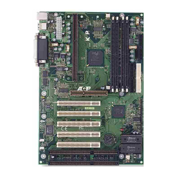
- Page 4 Installation BX5 Detailed Layout Figure 1 Page 3...
-
Page 5: Installation
Installation The following must be completed before powering on your new system: Configure Jumpers System memory Configuration Device Connectors The following will describe all of the setting that you are required to set before moving on to step 2. ROM PCI/ISA BIOS(2A69KPAG) SENSOR &... - Page 6 Installation I I I Note: Based on the implementation of the Intel 440BX AGPset, the BX5 is able to provide multiple front side bus (FSB) frequencies for Slot 1 processors and memory operations. The FSB is easily se- motherboard's lected by BIOS Setup listed above to match the FSB required by your processor.
- Page 7 Installation J P 4 K ey b o a rd P o w er -O N fu n ctio n J P 4 1 -2 - E n a b led 2-3 - N or m al (D e fa u lt) JP 5 C M O S C lea r J P 1...
- Page 8 Installation The BX5 supports (4) 168-pin DIMMs (Dual In-line Memory Module). The DIMMs can be either EDO (Extended Data Out) or SDRAM (Synchronized DRAM). • We recommend not mixing SDRAM DIMM and EDO DIMM together. • EDO DIMM can only be used with the 66MHz FSB.
- Page 9 Installation Please install the motherboard into the chassis. Now that your motherboard is installed you are ready to connect all your connec- tions (figure 10). Parallel Port PS/2 Mouse PS/2 Keyboard COM2 COM1 Figure 10 J2,J3: Chassis Panel Connector • Power LED, Speaker, Reset, Turbo LED, HDD LED, IR Conn., Sleep/ Power_ON CPU Fan Power •...
-
Page 10: Power On/Off
Installation (This is connected to the power button on the case. Using the Soft- Off by Pwr-BTTN feature, you can choose either Instant Off (turns system off or 4 sec delay (you need to hold the button immediately), down for 4 seconds before the system turns off). When the system is in 4 sec delay mode, there is a special feature to make the system to go into suspend mode when the button is pressed momentarily.) Power On/Off...
Need help?
Do you have a question about the BX5 and is the answer not in the manual?
Questions and answers