NordicTrack T 5.5 Treadmill User Manual
English manual
Hide thumbs
Also See for T 5.5 Treadmill:
- User manual (33 pages) ,
- Manuel de l’utillsateur manual (32 pages) ,
- Quick assembly manual (4 pages)
Table of Contents
Advertisement
www.nordictrack.com
USER'S MANUAL
Model No. NTL60011.3
Serial No.
Write the serial number in the space
above for reference.
Serial Number
Decal
QUESTIONS?
If you have questions, or if parts
are damaged or missing, DO NOT
CONTACT THE STORE; please
contact Customer Care.
IMPORTANT: Please register this
product (see the limited warranty
on the back cover of this manual)
before contacting Customer Care.
CALL TOLL-FREE:
1-800-TO-BE-FIT
(1-800-862-3348)
Mon.–Fri. 6 a.m.–6 p.m. MT
Sat. 8 a.m.–4 p.m. MT
ON THE WEB:
www.nordictrackservice.com
CAUTION
Read all precautions and instruc-
tions in this manual before using
this equipment. Keep this manual
for future reference.
Advertisement
Table of Contents

Subscribe to Our Youtube Channel
Related Manuals for NordicTrack T 5.5 Treadmill


Summary of Contents for NordicTrack T 5.5 Treadmill
- Page 1 USER’S MANUAL Model No. NTL60011.3 Serial No. Write the serial number in the space above for reference. Serial Number Decal QUESTIONS? If you have questions, or if parts are damaged or missing, DO NOT CONTACT THE STORE; please contact Customer Care.
-
Page 2: Table Of Contents
Apply the decal in the location shown. Note: The decals may not be shown at actual size. NORDICTRACK is a registered trademark of ICON IP, Inc. -
Page 3: Important Precautions
14. To purchase a surge suppressor, see your local 4. The treadmill is intended for home use only. NORDICTRACK dealer, call the telephone Do not use the treadmill in any commercial, number on the front cover of this manual, or rental, or institutional setting. - Page 4 20. The heart rate monitor is not a medical 24. Do not change the incline of the treadmill by device. Various factors, including the user’s placing objects under the treadmill. movement, may affect the accuracy of heart rate readings. The heart rate monitor is 25.
-
Page 5: Before You Begin
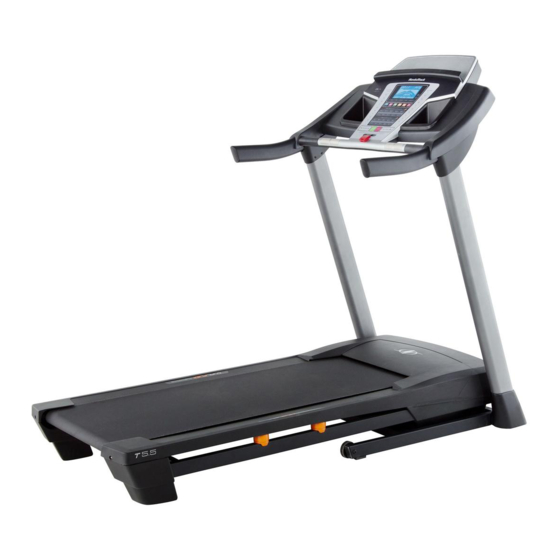
BEFORE YOU BEGIN Thank you for selecting the new NORDICTRACK T5.5 manual. To help us assist you, note the product model ® treadmill. The T5.5 treadmill provides an impressive number and serial number before contacting us. The selection of features designed to make your workouts model number and the location of the serial number at home more effective and enjoyable. -
Page 6: Part Identification Chart
PART IDENTIFICATION CHART Use the drawings below to identify small parts used for assembly. The number in parentheses below each draw- ing is the key number of the part, from the PART LIST near the end of this manual. The number following the key number is the quantity used for assembly. -
Page 7: Assembly
ASSEMBLY • Assembly requires two persons. • To identify small parts, see page 6. • Place all parts in a cleared area and remove the • Assembly requires the following tools: packing materials. Do not dispose of the packing the included hex keys materials until you finish all assembly steps. - Page 8 2. Identify the Left Upright (75). Have a second person hold the Left Upright near the Base (80). See the inset drawing. Tie the wire tie in the Wire Left Upright (75) securely around the end of the Upright Wire (70). Then, insert the Upright Wire into the lower end of the Left Upright as you pull Wire the other end of the wire tie out of the upper end...
- Page 9 4. Identify the Left and Right Base Covers (73, 74). Slide the Left and Right Base Covers onto the Left and Right Uprights (75, 76) as shown. Identify the Left and Right Upright Covers (92, 93). Slide the Left and Right Upright Covers onto the Left and Right Uprights (75, 76) as shown.
- Page 10 6. Remove the tie from the 5/16" Cage Nut (90). If necessary, press the Cage Nut back into place. Attach the Right Handrail (72) to the Right Upright (76) with a 5/16" x 1" Bolt (7), a 5/16" Star Washer (8), and two 5/16" x 1" Flat Head Screws (10) as shown.
- Page 11 8. IMPORTANT: To avoid damaging the Pulse Crossbar (31), do not use power tools and do not overtighten the #10 x 3/4" Screws (13). Orient the Pulse Crossbar (31) as shown. Start one #10 x 3/4" Screw (13) with one #10 Star Washer (11) into each end of the Pulse Crossbar and each of the Handrails (71, 72).
- Page 12 10. Set the console assembly on the Left and Right Console Handrails (71, 72). Make sure that no wires Assembly are pinched. Insert the excess Upright Wire (not shown) into the Left Handrail and the ground wires (not shown) into the console assembly.
- Page 13 13. Raise the Frame (49) to the position shown. Have a second person hold the Frame until this step is completed. Orient the Storage Latch (51) so that the large barrel and the latch knob are oriented as shown. Attach the lower end of the Storage Latch (51) to the Base (80) with a 3/8"...
-
Page 14: Operation And Adjustment
OPERATION AND ADJUSTMENT HOW TO CONNECT THE POWER CORD nominal 120-volt circuit capable of carrying 15 or more amps. To avoid overloading the circuit, do Use a Surge Suppressor not plug other electrical devices, except for low- power devices such as cell phone chargers, into Your treadmill, like other electronic equipment, can be the surge suppressor or into an outlet on the same circuit. - Page 15 CONSOLE DIAGRAM FEATURES OF THE CONSOLE You can even listen to your favorite workout music or audio books with the console’s premium stereo sound The treadmill console offers an impressive array of system while you get in shape. features designed to make your workouts more effec- tive and enjoyable.
- Page 16 HOW TO TURN ON THE POWER HOW TO USE THE MANUAL MODE IMPORTANT: If the treadmill has been exposed to 1. Insert the key into the console. cold temperatures, allow it to warm to room tem- perature before turning on the power. If you do not See HOW TO TURN ON THE POWER at the left.
- Page 17 4. Change the incline of the treadmill as desired. The My Trail tab will show a track that represents 1/4 mile (400 m). As you exercise, the flashing To change the incline of the treadmill, press the rectangle will show your progress. The My Trail tab Incline increase or decrease button or one of the will also show the number of laps you complete.
- Page 18 6. Measure your heart rate if desired. W hen you are finished using the treadmill, press the power switch into the off position and unplug Before using the the power cord. IMPORTANT: If you do not do this, the treadmill’s electrical components may heart rate moni- wear prematurely. tor, remove the sheets of plastic from the metal...
-
Page 19: To Use An Onboard Workout
HOW TO USE AN ONBOARD WORKOUT The workout will continue in this way until the last segment of the profile flashes in the display and the 1. Insert the key into the console. last segment ends. The walking belt will then slow to a stop. See HOW TO TURN ON THE POWER on page 16. Note: The calorie goal is an estimate of the 2. - Page 20 HOW TO USE AN IFIT WORKOUT workout, the display will count down to the begin- ning of the race. Note: To use an iFit workout, you must have an optional iFit module. To purchase an iFit module at Note: Each iFit button may also run two demo any time, go to www.iFit.com or call the telephone workouts.
-
Page 21: The Information Mode
THE INFORMATION MODE console. However, when you remove the key, the displays will remain lit, although the buttons will not The console features an information mode that keeps function. If the demo mode is turned on, the word track of treadmill information and allows you to person- ON will appear in the matrix. -
Page 22: How To Fold And Move The Treadmill
HOW TO FOLD AND MOVE THE TREADMILL HOW TO FOLD THE TREADMILL HOW TO MOVE THE TREADMILL To avoid damaging the treadmill, adjust the incline Before moving the treadmill, fold it as described at the to the lowest position before you fold the treadmill. left. -
Page 23: Troubleshooting
TROUBLESHOOTING Most treadmill problems can be solved by following SYMPTOM: The console displays remain lit when the simple steps below. Find the symptom that you remove the key from the console applies, and follow the steps listed. If further assis- tance is needed, see the front cover of this manual. - Page 24 SYMPTOM: The walking belt slows when walked on SYMPTOM: The walking belt is off-center or slips when walked on a. Use only a surge suppressor that meets all of the a. If the walking belt is off-center, first remove the specifications described on page 14. key and UNPLUG THE POWER CORD. If the b.
-
Page 25: Exercise Guidelines
EXERCISE GUIDELINES Burning Fat—To burn fat effectively, you must exer- WARNING: cise at a low intensity level for a sustained period of Before beginning this time. During the first few minutes of exercise, your or any exercise program, consult your physi- body uses carbohydrate calories for energy. - Page 26 SUGGESTED STRETCHES The correct form for several basic stretches is shown at the right. Move slowly as you stretch —never bounce. 1. Toe Touch Stretch Stand with your knees bent slightly and slowly bend forward from your hips. Allow your back and shoulders to relax as you reach down toward your toes as far as possible.
-
Page 27: Part List
PART LIST Model No. NTL60011.3 R1112A Key No. Qty. Description Key No. Qty. Description #8 x 1/2" Ground Screw Frame Spacer 3/8" x 2 1/2" Bolt Frame 3/8" Nut Right Foot Rail 3/8" x 4" Screw Storage Latch 3/8" Star Washer Right Rear Foot #8 x 3/4"... -
Page 28: Exploded Drawing
EXPLODED DRAWING A Model No. NTL60011.3 R1112A... - Page 29 EXPLODED DRAWING B Model No. NTL60011.3 R1112A...
- Page 30 EXPLODED DRAWING C Model No. NTL60011.3 R1112A...
- Page 31 EXPLODED DRAWING D Model No. NTL60011.3 R1112A...
-
Page 32: Ordering Replacement Parts
ORDERING REPLACEMENT PARTS To order replacement parts, please see the front cover of this manual. To help us assist you, be prepared to pro- vide the following information when contacting us: • the model number and serial number of the product (see the front cover of this manual) • the name of the product (see the front cover of this manual) • t he key number and description of the replacement part(s) (see the PART LIST and the EXPLODED DRAWING near the end of this manual) LIMITED WARRANTY IMPORTANT: You must register this product within 30 days of the purchase date to avoid added fees for service needed under warranty.
Need help?
Do you have a question about the T 5.5 Treadmill and is the answer not in the manual?
Questions and answers
Why does my incline keep going up and down and not allow me to stop it. When I turned it on it started doing this and not allowing me to do anything else. Notice track Series 5. I tried unplugging and no change.
The NordicTrack T5.5 Treadmill incline may keep adjusting automatically and not allow manual control because it needs recalibration. To recalibrate the incline system, hold down the Stop button and the Speed increase button while inserting the key into the console. Then release both buttons, press the Stop button, and press the Incline increase or decrease button. The treadmill will automatically adjust to the maximum incline and then return to the minimum level. If it does not begin calibrating, press the Stop button again and repeat the process. Once calibration is complete, remove the key from the console.
This answer is automatically generated