Table of Contents
Advertisement
www.nordictrack.com
Model No. NTL61011.1
Serial No.
Write the serial number in the space
above for reference.
Serial Number
Decal
QUESTIONS?
if you have questions, or if parts
are damaged or missing, DO NOT
CONTACT THE STORE; please
contact Customer Care.
iMPORTANT: Please register this
product (see the limited warranty
on the back cover of this manual)
before contacting Customer Care.
CALL TOLL-FREE:
1-800-TO-BE-FiT
(1-800-862-3348)
Mon.=Fri. 6 a.m.=6 p.m. MT
Sat. 8 a.m.=4 p.m. MT
ON THE WEB:
www.nordictrackservice.com
;ER'S
A UAL
Advertisement
Table of Contents

Related Manuals for NordicTrack T5.7 NTL61011.1


Summary of Contents for NordicTrack T5.7 NTL61011.1
- Page 1 Model No. NTL61011.1 Serial No. Write the serial number in the space ;ER'S A UAL above for reference. Serial Number Decal QUESTIONS? if you have questions, or if parts are damaged or missing, DO NOT CONTACT THE STORE; please contact Customer Care.
- Page 2 • Hold ha_drails preven_ fall_ng, and always wear te safety clp while operating treadmill. • Stop f you feel faint, tizzy, or short of b_eath, KEEP HANDSAND FEETAWAY FROMTHISAREAWHILETHE TREADMILLiS IN OPERATION. NORDICTRACK is a registered trademark of ICON IP, Inc.
- Page 3 14. To purchase a surge suppressor, informed of all warnings and precautions. see your local NORDICTRACK dealer or call the telephone number on the front cover of Use the treadmill only as described.
- Page 4 20. Never leave the treadmill unattended while DANGER.Always unplugthe power it is running. Always remove the key, unplug cord immediately after use, before clean- the power cord, and press the power switch ing the treadmill, and before performing the into the off position when the treadmill is not maintenance and adjustment...
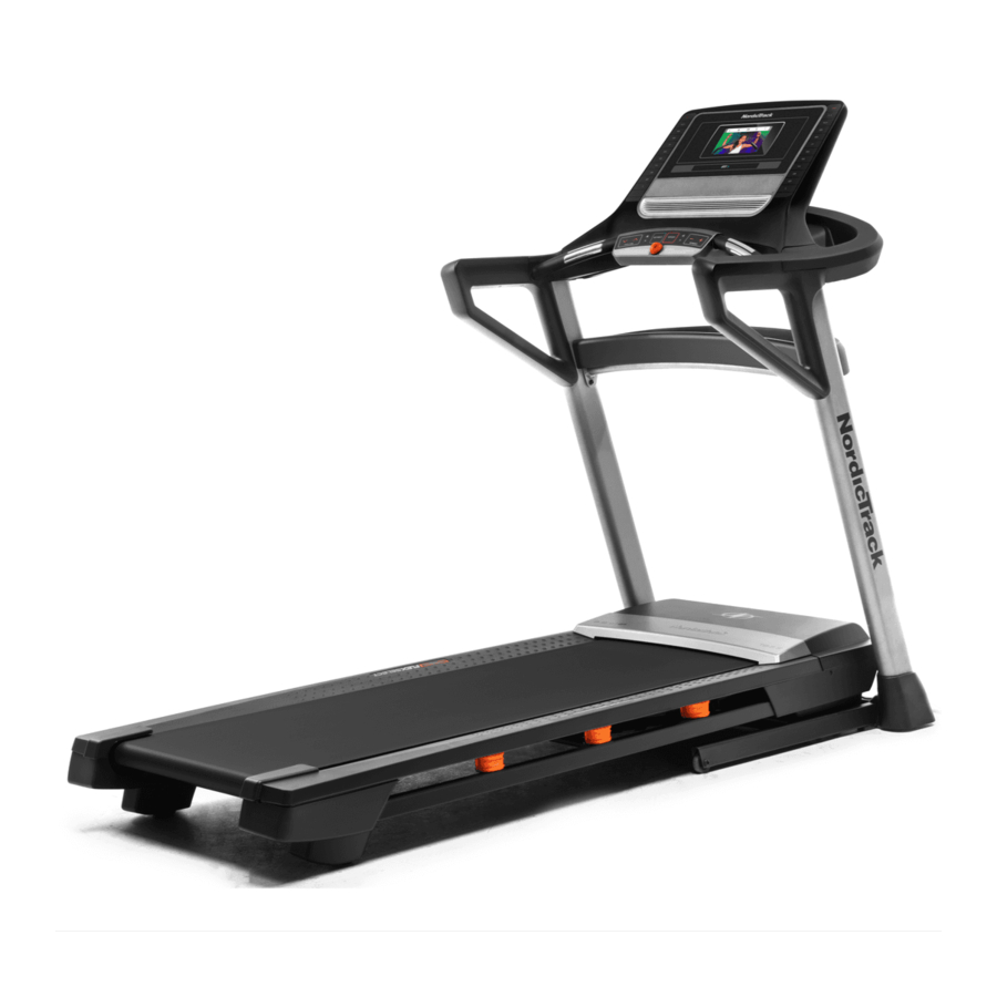
- Page 5 BEFORE YOU BEGIN Thank you for selecting the new NORDICTRACK <°_' T5.7 manual. To help us assist you, note the product model treadmill. The T5.7 treadmill provides an impressive number and serial number before contacting us. The model number and the location of the serial number selection of features designed to make your workouts decal are shown on the front cover of this manual.
- Page 6 PART iDENTiFiCATiON CHART Use the drawings below to identify small parts used for assembly. The number in parentheses below each draw- ing is the key number of the part, from the PART LIST near the end of this manual. The number following the key number is the quantity used for assembly.
-
Page 7: Assembly
ASSEMBLY Assembly requires two persons. Assembly requires the following tools: the included hex keys Place all parts in a cleared area and remove the packing materials. Do not dispose of the packing one adjustable wrench materials until you finish all assembly steps. one Phillips screwdriver The underside of the walking belt is coated with high-performance... - Page 8 Identify the Left Upright (75), which is marked "Left." Have a second person hold the Left Upright near the Base (80). Wire See the inset drawing. Tie the wire tie in the Left Upright (75) securely around the end of the Upright Wire (70).
- Page 9 Identify the Left and Right Base Covers (73, 74), which are marked "L" and "R." Slide the Left and Right Base Covers onto the Left and Right Uprights (75, 76) as shown. Identify the Left Handrail (71), which is marked "Left."...
- Page 10 Attach the Right Handrail (72) to the Right Upright (76) with two 3/8" x 3 1/2" Screws (9) and two 3/8" Star Washers (5). Start both Screws, but do not tighten them yet. Remove the four 1/4" x 1" Screws (10) from the Console Frame (87).
- Page 11 Insert the Console Frame (87) into the Handrails (71, 72). Attach the Console Frame with the four 1/4" x 1" Screws (10) that you removed in step 8. Start all four Screws, and then tighten them. Be careful not to pinch the Upright Wire (not shown).
- Page 12 10. Set the console assembly on the Left and Right Console Handrails (71, 72). Make sure that no wires are pinched. Insert the excess Upright Wire (70) into the Left Handrail. Attach the console assembly to the brackets on the Handrails (71, 72) with two 5/16"x 1"...
- Page 13 13. Raise the Frame (49) to the position shown. Have a second person hold the Frame until this step is completed. Orient the Storage Latch (51) so that the large barrel and the latch knob are oriented as shown. Attach the lower end of the Storage Latch (51) to the Base (80) with a 3/8"...
- Page 14 OPERATION AND ADJUSTMENT HOW TO PLUG iN THE POWER CORD This product is for use on a nominal 120-volt circuit (see drawing 1). A temporary adapter may be used to connect the surge suppressor to a 2-pole receptacle if a properly-grounded outlet is not available (see drawing 2).
- Page 15 CONSOLE DIAGRAM FEATURES OFTHECONSOLE You can even listen to your favorite workout music or audio books with the console's premium stereo sound The treadmill console offers an impressive array of system while you get in shape. features designed to make your workouts more effec- tive and enjoyable.
- Page 16 HOW TO TURN ON THE POWER HOW TO USE THE MANUAL MODE iMPORTANT: if the treadmill has been exposed to insert the key into the console. cold temperatures, allow it to warm to room tern= See HOW TO TURN ON THE POWER at the left. perature before turning on the power, if you do not do this, you may damage the console displays or Select the manual mode.
- Page 17 Change the incline of the treadmill as desired. The Speed tab will show a profile of the speed set- tings of the workout. To change the incline of the treadmill, press the Incline increase or decrease button or one of the The My Trail tab will show a track that represents numbered Quick Incline buttons.
- Page 18 Measure your heart rate if desired. When you are finished using the treadmill, press the power switch into the off position and unplug Before using the the power cord. IMPORTANT: If you do not do heart rate moni- this, the treadmill's electrical components tor, remove the wear prematurely.
- Page 19 HOW TO USE AN ONBOARD WORKOUT The workout will continue in this way until the last segment of the profile flashes in the display and the insert the key into the console. last segment ends. The walking belt will then slow to a stop.
- Page 20 HOW TO USE AN IFIT LiVE WORKOUT calories you will burn. The display may also show the name of the workout. If you select a competition Note: To use an iFit Live workout, you must have an workout, the display will count down to the begin- optional iFit Live module.
- Page 21 THE iNFORMATiON MODE 3. CONTRAST LVL: Press the Incline increase and decrease buttons to adjust the contrast level of the The console features an information mode that keeps display. track of treadmill information and allows you to person- alize console settings. if a module is connected, you may also select the following...
- Page 22 HOW TO FOLD AND MOVE THE TREADMILL HOW TO FOLD THE TREADMILL HOW TO MOVE THE TREADMILL To avoid damaging the treadmill, adjust the incline Before moving the treadmill, fold it as described at the left. CAUTION: Make sure that the latch knob is to the lowest position before you fold the treadmill.
- Page 23 TROUBLESHOOTING Most treadmill problems can be solved by following Remove the key from the console, and then reinsert it. the simple steps below. Find the symptom that applies, and follow the steps listed, if further assis- tance is needed, see the front cover of this manual. If the treadmill still will not run, please see the front cover of this manual.
- Page 24 Locate the Reed Switch (95) and the Magnet (44) If the walking belt is overtightened, treadmill per- on the left side of the Pulley (43). Turn the Pulley formance may decrease and the walking belt may until the Magnet is aligned with the Reed Switch. become damaged.
- Page 25 SYMPTOM: The walking belt is off=center or slips if the walking belt slips when walked on, first re- when walked on move the key and UNPLUG THE POWER CORD. Using the hex key, turn both idler roller screws if the walking belt is off-center, first remove the clockwise, 1/4 of a turn.
- Page 26 EXERCISE GUiDELiNES Burning Fat--To burn fat effectively, you must exer- cise at a low intensity level for a sustained period of time. During the first few minutes of exercise, your body uses carbohydrate calories for energy. Only after the first few minutes of exercise does your body begin to use stored fat calories for energy.
- Page 27 PART LIST Model No. NTL61011.1 R0811B Key No. Qty. Description Key No. Qty. Description #8 x 1/2" Ground Screw Left Rear Foot 3/8" x 2 1/2" Bolt #8 x 1/2" Ground Screw 3/8" Nut #8 x 1/2" Controller Screw 3/8" x 4" Screw Idler Roller 3/8"...
- Page 28 "U r" ,,,,,&...
- Page 29 EXPLODED DRAWING B Model No. NTL61011.1 R0811B 6--g...
- Page 30 EXPLODED DRAWING C Model No. NTL61011.1 R0811B...
Need help?
Do you have a question about the T5.7 NTL61011.1 and is the answer not in the manual?
Questions and answers
is it necessary to lubricate any parts of this treadmill?
No, it is not necessary to lubricate parts of the NordicTrack T5.7 treadmill unless instructed by an authorized service representative. Applying silicone spray or other substances to the walking belt or walking platform without instruction may cause deterioration and excessive wear.
This answer is automatically generated