Table of Contents
Advertisement
Quick Links
Advertisement
Table of Contents

Related Manuals for Outback GS8048


Summary of Contents for Outback GS8048
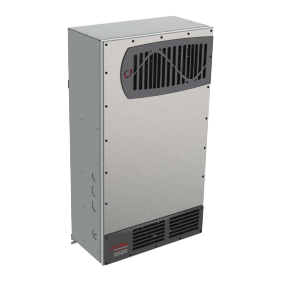
- Page 1 Radian Series Inverter/Charger GS8048 Installation Manual...
-
Page 2: Contact Information
ANY SUCH INFORMATION WILL BE ENTIRELY AT THE USER’S RISK. Warranty Summary OutBack Power Technologies Inc. warrants that the products it manufactures will be free from defects in materials and workmanship for a period of five (5) years subject to the conditions set forth in the warranty detail, found in the Radian Series Inverter/Charger Operator’s Manual. -
Page 3: Important Safety Instructions
Important Safety Instructions READ AND SAVE THESE INSTRUCTIONS! This manual contains important safety instructions for the Radian Series Inverter/Charger. Read all instructions and cautionary markings on the inverter and on any accessories or additional equipment included in the installation. Failure to adhere to these instructions could result in severe shock or possible electrocution. -
Page 4: Definitions
Direct Current; refers to voltage produced by the batteries or renewable source Digital Voltmeter Electrical Testing Laboratories; short for the company ETL Semko; refers to a certification issued by ETL to OutBack products indicating that they meet certain UL standards GFDI Ground Fault Detector Interruptor; a safety device for PV systems Ground;... -
Page 5: General Safety
This equipment is NOT intended for use with life support equipment or other medical equipment or devices. CAUTION: Equipment Damage Only use components or accessories recommended or sold by OutBack Power Technologies or its authorized agents. IMPORTANT: Do not attempt to install this equipment if it appears to be damaged in any way. See the Warranty section for instructions on returning the equipment. -
Page 6: Inverter Safety
(rated for a minimum 1000 Vac and 1000 Vdc) to verify the de- energized condition. Do not perform any servicing other than that specified in the installation instructions unless qualified to do so, or have been instructed to do so by OutBack Power Technologies Technical Support personnel. WARNING: Burn Hazard Internal parts can become hot during operation. -
Page 7: Battery Safety
Battery Safety WARNING: Explosion, Electrocution, or Fire Hazard Use the battery types recommended by OutBack Power Technologies. Follow the battery manufacturer’s recommendations for installation and maintenance. Ensure the cables are properly sized. Failure to size the cables properly can result in a fire hazard. -
Page 8: Regulatory Specifications
Additional Information Regulatory Specifications See the Radian Series Inverter/Charger Operator’s Manual for all specifications and regulatory information, including certifications. Required Resources This product is required to be installed according to pertinent safety codes and standards. If installed in the United States, wiring practices must meet the requirements of the National Electrical Code (NEC). -
Page 9: Recycling Information
Additional Information Recycling Information IMPORTANT: Recycle Electronics and Batteries Batteries are considered hazardous waste and must be recycled according to local jurisdiction. Inverters and other electronics contain metals and plastics that should also be recycled. The following web sites and phone numbers provide additional information for recycling electronic products and batteries. - Page 10 Additional Information Natural Resources Canada Address: 580 Booth, Ottawa, ON K1A 0E8 Web site: http://www.nrcan-rncan.gc.ca/mms-smm/busi-indu/rec-rec-eng.htm Phone: +1.613.995.0947 TTY: +1.613.996.4397 (Phone and TTY: Monday to Friday, 8:30 a.m. to 4:30 p.m. ET) Office of Waste Management, Canada Web site: http://www.portaec.net/library/recycling/recycling_in_canada.html Address: Office of Waste Management Conservation and Protection Environment Canada...
-
Page 11: Table Of Contents
Regulatory Specifications ..............................6 Required Resources ................................6 Additional Resources ................................6 Recycling Information ................................ 7 Introduction ....................11 Welcome to OutBack Power Technologies ......................11 Components and Accessories ............................12 Planning ....................13 Applications ..................................13 Renewable Energy ................................14 Battery Bank .................................. - Page 12 Figure 23 Three-Wire Generator Start (Example) .................. 33 Figure 24 Single-Inverter Wiring ......................... 34 Figure 25 OutBack HUB4 and MATE3 ....................... 35 Figure 26 Example of Parallel Stacking Arrangement (Three Inverters)........36 Figure 27 Parallel Wiring ..........................37 900-0021-01-00 Rev B...
-
Page 13: Introduction
Introduction Welcome to OutBack Power Technologies Thank you for purchasing the OutBack Radian Series Inverter/Charger. This product offers a complete power conversion system between batteries and AC power. It can provide backup power, sell power back to the utility grid, or provide complete stand-alone off-grid service. -
Page 14: Components And Accessories
Optional Components for Attachment to Radian Inverter MATE3 System Display and Controller FLEXmax 60 or FLEXmax 80 Charge Controller FW-MB3 (MATE3 bracket) FW-CCB or FW-CCB2 (charge controller brackets) GSLC, GSLC175-120/240, or GSLC-PV-120-/240 OutBack HUB4 or HUB10 (GS Load Centers) MATE3 FLEXmax Charge Controllers GSLC... -
Page 15: Planning
Planning Applications The Radian Series Inverter/Charger is intended for both grid-interactive and off-grid applications. These inverters are designed to use a battery bank to store energy. They can work in conjunction with photovoltaic (PV) panels to harvest solar energy, as well as wind turbines and other renewable sources. -
Page 16: Renewable Energy
The renewable source is always treated as a battery charger, even if all of its power is used immediately. The renewable source must have a charge controller or some way to prevent overcharging. OutBack Power’s FLEXmax family of charge controllers can be used for this purpose, as can other products. -
Page 17: Generator
Planning Typical grid loss is 30 minutes or less, or The loads are less than 2 kW. NOTE: If support time or load size are disproportionate to the bank size, they will cause inverter shutdown due to low battery voltage after a short time. These conditions could be detrimental to the life of a small battery bank. -
Page 18: Maintenance Bypass Switching
Planning Maintenance Bypass Switching Inverter systems are often equipped with AC maintenance bypass switches or interlocks. If the inverter system ever needs to be shut down or removed, the AC sources and loads must be disconnected. A bypass device allows the AC source to deliver power directly to the loads, bypassing the inverter. -
Page 19: Installation
Installation Location and Environmental Requirements Radian Series Inverter/Chargers must be located in a weather-proof enclosure or enclosed area. These inverters are not designed for exposure to water or excessive wind-blown dust and debris. The Radian inverter must be wall-mounted in an upright position. The inverter is not approved for mounting in any other position or orientation. -
Page 20: Tools Required
IMPORTANT: Use correct fasteners to secure the mounting plate and the Radian inverter/charger to the mounting surface. OutBack cannot be responsible for damage to the product if it is attached with inadequate fasteners. The Radian inverter/charger comes equipped with a mounting plate, as shown in Figure 7. -
Page 21: Figure 8 Mounting The Inverter
Installation …continued from the previous page… Place the Radian inverter against the wall and slide it directly over the upper lip of the mounting plate. The inverter’s mounting flange should come to rest within the lip so that it hangs securely. GS Inverter To assist in alignment, dimples have been placed on the side of the unit to mark the lower edge of the flange. -
Page 22: Accessory Mounting
NOTE: The OutBack FLEXmax Extreme should be installed on the wall to either side of the GSLC for direct wiring access and does not require additional brackets. -
Page 23: Removing Front Cover
Installation Removing Front Cover The front cover must be removed in order to access the Radian inverter’s AC terminals and other connections. These include the “Remote” and “Batt Temp” ports, as well as several sets of auxiliary terminals. Twenty-two machine screws are located around the perimeter. Remove these screws with a Phillips screwdriver. -
Page 24: Terminals And Ports
Installation Terminals and Ports DC TERMINALS: Connect to battery cables and DC system. There are two DC positive and two DC negative terminals. Each DC positive terminal requires separate cables and separate overcurrent protection. See page 25 for instructions. RIBBON CABLES: Connect the Radian’s power modules and control board. -
Page 25: Figure 12 Ac Terminals, Ports, And Ground Bus
Installation CONTROL WIRING TERMINAL BLOCK: Receives control wires for a variety of functions, including generator control. See facing page for terminal descriptions. REMOTE and BATTERY TEMP JACKS: Receive the RJ45 and RJ11 plugs from the MATE3 system display and Remote Temp Sensor. See page 28 for instructions. -
Page 26: Grounding
For all installations, the negative battery conductor should be bonded to the grounding system at only one point. If the OutBack GFDI is present, it can provide the bond. (The GSLC is also equipped with its own bond, which may need to be removed.) IMPORTANT: OutBack products are not designed for use in a positive-grounded system. -
Page 27: Dc Wiring
Inverter Nominal DC Amps Conductor Size Breaker (Minimum, per breaker) (Minimum, per breaker) Size (Derated 125%) GS8048 2/0 AWG (0.105 in²) or 70 mm² 175 Adc Terminal Location Torque Requirements Inverter DC Terminals 60 in-lb (6.9 Nm) Battery Terminals See battery manufacturer’s recommendations When installing DC cables: Make certain DC circuit breakers are turned to the off position, or fuses are removed, before proceeding. -
Page 28: Ac Wiring
Installation AC Wiring WARNING: Shock Hazard Ensure there is only one AC neutral-ground bond at any time. Some codes require the bond to be made at the main panel only. The GSLC is equipped with its own bond, which may need to be removed. IMPORTANT: The AC input and output must be protected with branch-rated circuit breakers of up to 50 Aac maximum size to meet NEC or other code requirements. -
Page 29: Ac Sources
Installation The Radian cannot take voltage other than 120/240 Vac. If wires are 120 Vac each, but do not measure 240 Vac from one to the next (such as two legs of a 3-phase source), it will not accept the power. The AC source(s) can power both battery charger and loads if sized correctly. -
Page 30: Accessory Wiring
Installation Accessory Wiring has p The upper board orts for both the Remote Temperature Sensor (RTS) and the Remote port MATE3 system display. The system display port is labeled Remote. The RTS port is labeled Battery Temp. If a HUB is in use, it occupies the inverter’s Battery Temp port Remote port. -
Page 31: Aux Wiring
Installation AUX Wiring The Radian inverter has two sets of terminals which can respond to different criteria and control many functions. These include cooling fans, vent fans, load diversion, fault alarms, and the Advanced Generator Start (AGS) function. The 12V AUX terminals are a switched 12 Vdc power supply. They can control any of the Auxiliary Output functions available in the MATE3. -
Page 32: Figure 20 Aux Connections For Diversion (Example)
Installation In this example, the 12V AUX terminals drive a relay that diverts wind power. The relay’s coil is connected to the 12V AUX terminals. When the AUX function closes the relay (based on battery Turbine voltage), the relay diverts the excess wind power to a water heating element. -
Page 33: Generator Control
Installation Generator Control The RELAY AUX terminals can most easily perform “two-wire” generator start. A two-wire-start generator is the simplest type, where the cranking and starting routine is automated. It usually has a single switch with two positions that is turned ON to start, OFF to stop. Two-Wire-Start (RELAY AUX Terminals) The RELAY AUX terminals can be wired in place of the generator’s start switch as shown below. -
Page 34: Figure 22 Two-Wire Generator Start (12V Aux)
12V AUX terminals to energize the coil of a 12 Vdc automotive or similar relay. Depicted is the OutBack FLEXware Relay Assembly, which is sold for this purpose. The relay contacts can serve in place of the generator’s start switch. The battery shown below is depicted for clarity. In most cases, it is part of the generator’s internal starting circuit and is not an external component. -
Page 35: Figure 23 Three-Wire Generator Start (Example)
Atkinson Electronics (http://atkinsonelectronics.com) is one company that makes these kits. The Atkinson GSCM-Mini is intended to work with OutBack inverters. NOTE: The conversion kit requires a 12-volt signal which the RELAY AUX terminals cannot provide. -
Page 36: Single-Inverter Ac Installations
Installation Single-Inverter AC Installations When installing an inverter AC system, the following rules must be observed. All overcurrent devices in building-based installations must be sized for 50 Aac or less. All wiring in building-based installations must be sized for 50 Aac or more. ... -
Page 37: Multiple-Inverter Ac Installations (Stacking)
This requires stacking. Stacking refers to how the inverters are wired within the system and then programmed to coordinate activity. Stacking allows all units to work together as a single system. The Radian Series GS8048 inverter/charger can stack up to ten units in parallel. Stacking Connections Stacking requires an OutBack HUB Communications Manager, as well as a MATE3 system display. -
Page 38: Figure 26 Example Of Parallel Stacking Arrangement (Three Inverters)
Installation Parallel Stacking (Dual-Stack and Larger) In parallel stacking, two or more inverters are stacked to create a single, common AC bus. The slave outputs are controlled directly by the master and cannot operate independently. All inverters share a common input (AC source) and run loads on a common output. ... -
Page 39: Figure 27 Parallel Wiring
Installation Figure 27 Parallel Wiring 900-0021-01-00 Rev B... -
Page 40: Functional Test
Installation Functional Test Once the mounting, wiring, and other installation steps are completed, proceed to the Radian Series Inverter/Charger Operator’s Manual. The Operator’s Manual has steps for system commissioning. These include powering up and performing a functional test on the inverter system, as well as powering down and adding new devices to an existing system. -
Page 41: Index
Index Front Cover ................21 AC Wiring ................ 23, 26 Advanced Generator Start ..........29 Generator ........... 13, 26, 27, 29, 36 Audience ................... 1 Control ................31 AUX ................2, 22, 29 Sizing.................. 15 GFDI ..................2, 24 Grid-Interactive ..............2 Grounding .............. - Page 42 Index Terms and Definitions ............2 Test ................... 38 Three-Phase ................26 Recycling Information ............7 Tools Required ..............18 Regulatory ................6 Torque Requirements Remote System Display ............3 DC Terminals ..............25 Remote Temperature Sensor (RTS) ... 2, 12, 23, 28 Ground Terminals ............
- Page 43 THIS PAGE INTENTIONALLY LEFT BLANK.
- Page 44 Corporate Headquarters European Office 17825 – 59 Avenue N.E. Hansastrasse 8 Suite B D-91126 Arlington, WA 98223 USA Schwabach, Germany +1.360.435.6030 +49.9122.79889.0 900-0021-01-00 Rev B...
Need help?
Do you have a question about the GS8048 and is the answer not in the manual?
Questions and answers
WHERE DO YOU FIND INSTRUCTIONS FOR OFF-GRID INSTALL