Table of Contents
Advertisement
Advertisement
Table of Contents

Related Manuals for Outback FX Series


Summary of Contents for Outback FX Series
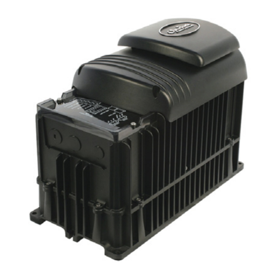
- Page 1 FX Inverter/Charger FX and VFX Mobile Series Installation Manual...
-
Page 2: Contact Information
FX and VFX Mobile Series Inverter/Charger Installation Manual © 2016 by OutBack Power Technologies. All Rights Reserved. Trademarks OutBack Power, the OutBack Power logo, FLEXware, and OPTICS RE are trademarks owned and used by OutBack Power Technologies, Inc. The ALPHA logo and the phrase “member of the Alpha Group” are trademarks owned and used by Alpha Technologies Inc. -
Page 3: Table Of Contents
Table of Contents Introduction ..................... 5 Audience ......................................5 Symbols Used ....................................5 Welcome to OutBack Power Technologies ......................... 6 General Safety ....................................6 Models ......................................7 Sealed Mobile Models ..................................... 7 Vented Mobile Models .................................... 7 ... -
Page 4: Figure 4 Dimensions 1
AUX Connections for Vent Fan (Example) ................ 2 4 Figure 18 Two‐Wire Generator Start (Example) .................. 2 5 Figure 19 Three‐Wire Generator Start (Example) ................. 2 6 Figure 20 Single‐Inverter Wiring ...................... 2 7 Figure 21 OutBack HUB10.3, MATE2 , and MATE3 ................ 2 8 Figure 22 Example of Classic Series Stacking Arrangement .............. 3 0 Figure 23 Classic Series Wiring ...................... 3 1 Figure 24 Example of OutBack Series Stacking Arrangement ............... 3 2 Figure 25 OutBack Series Wiring (Two Inverters) .................. 3 3 ... -
Page 5: Introduction
Introduction Audience This book provides instructions for the physical installation and wiring of this product. These instructions are for use by qualified personnel who meet all local and governmental code requirements for licensing and training for the installation of electrical power systems with AC and DC voltage up to 600 volts. -
Page 6: Welcome To Outback Power Technologies
Introduction Welcome to OutBack Power Technologies Thank you for purchasing the OutBack FX Mobile Series Inverter/Charger. This product offers a complete power conversion system between batteries, shore power, and generator. 12-, 24-, 32-, 36-, and 48-volt models Output power from 2.0 kVA to 3.6 kVA ... -
Page 7: Models
To compensate, most sealed models are also equipped with the OutBack Turbo Fan assembly which uses external air to remove heat from the chassis. FX2012MT (2.0 kVA output, 12 Vdc) ... -
Page 8: Components And Accessories
DCC provides space to mount other components such as a DC current shunt. AC Plate This plate is used for installations which do not utilize OutBack’s optional FLEXware conduit boxes. The knockouts are used to install strain relief for flexible cable. -
Page 9: Planning
Planning Applications OutBack inverter/chargers are designed to use a battery bank to store energy. In shore-based mobile and marine connections, the shore power is used as the primary source. When the shore power is removed, the inverter takes over to run the loads from the batteries. The settings can be changed to accommodate many applications. -
Page 10: Renewable Energy
A renewable source is always treated as a battery charger, even if all of its power is used immediately. The renewable source must have a charge controller, or some other regulation method, to prevent overcharging. OutBack Power’s FLEXmax family of charge controllers can be used for this purpose, as can other products. - Page 11 Source of information specified based on the rate of discharge. For example, A. Load Size Site-specific the OutBack EnergyCell 200RE is rated at 134.5 Ahr when discharged at the 5-hour rate (to terminal B. Daily Hours Site-specific voltage 1.85 Vpc). This is a high rate of discharge that C.
-
Page 12: Generator
A split-phase generator that is heavily loaded on one output line may suffer severely from balancing issues. The OutBack FW-X240 or PSX-240 balancing transformers may compensate for this condition. -
Page 13: Installation
The inverter will function, but will not necessarily meet its specifications, if operated in a temperature range of –0°F to 140°F (–40°C to 60°C). This is also the allowable temperature range for storage. The FX series of inverters carry an Ingress Protection (IP) rating of 20 and a Relative Humidity (RH) rating of 93% (non-condensing). -
Page 14: Mounting
Due to the variance in other mounting methods, OutBack only endorses the use of FLEXware mounting products or previous versions of OutBack mounting plates. Use M6 x 20 mm machine screws, one per corner, to attach the inverter to the mounting plate. Follow the instructions with each mounting system. -
Page 15: Terminals And Ports
Installation Terminals and Ports DC and AC DC TERMINALS GROUND TERMINALS These terminals connect to the battery cables and the DC system. These terminals connect to See page 18 for instructions. a grounding system for both batteries and AC. See page 15 for instructions. -
Page 16: Wiring
WARNING: Shock Hazard For all installations, the negative battery conductor should be bonded to the grounding system at only one point. If the OutBack GFDI is present, it can provide the bond. IMPORTANT: Not all OutBack products can be used in a positive-ground system. If it is necessary to build a positive-ground system with OutBack products, contact OutBack Technical Support at +1.360.618.4363 before proceeding. -
Page 17: Figure 6 Dc Ground Lug
Installation The inverter’s DC ground is a box lug located next to the negative DC battery terminal. This lug accepts up to 1/0 AWG (70 mm2 or 0.109 in2) wire. Local codes or regulations may require the DC ground to be run separately from the AC ground. -
Page 18: Dc Wiring
The DC terminals must be encased in an enclosure to meet the requirements of some local or national codes. Table 4 contains OutBack’s recommendations for minimum safe cable sizes. Other codes may supersede OutBack’s recommendations. Consult applicable codes for final size requirements. -
Page 19: Figure 8 Required Order Of Battery Cable Hardware
Installation To install DC cables and hardware: 1. Install all DC cables. Do not install hardware in a different order from Figure 8. The battery cable lug should be the first item installed on the stud. It should make solid contact with the mounting surface. ... - Page 20 Installation DC Cover or Turbo Fan Attachment COVER ATTACHMENT FX inverters are equipped with either the DC Cover or the Turbo Fan. To attach either cover, put the cover in place. Insert a screw at each corner using a Phillips screwdriver. As part of attaching the Turbo Fan, follow the wiring instructions in Figure 11.
-
Page 21: Ac Wiring
The installer is responsible for providing overcurrent protection. Install an approved 30 Aac circuit breaker on the inverter’s output. This page contains OutBack’s recommendations for minimum safe cable sizes. Other codes, particularly for mobile or marine applications, may supersede OutBack’s recommendations. Consult applicable codes for final size requirements. -
Page 22: Ac Sources
Installation AC Sources The inverter has a single set of AC terminals which are intended to connect to a single AC source. It cannot be directly wired to more than one AC source at the same time. If multiple sources are used, it is usually required to have a selector switch that changes from one to the next. -
Page 23: On And Off Wiring
Installation ON and OFF Wiring The INVERTER ON/OFF jumper bridges two pins. The ON/OFF jumper parallels the two INVERTER ON/OFF terminals on the Control Wiring Terminal Block. If either set of connections is closed, the inverter is ON. Because the jumper is factory-installed, the inverter usually remains ON unless given a command by the system display. -
Page 24: Aux Wiring
Installation AUX Wiring The AUX+ and AUX– terminals are a switched 12 Vdc supply. The AUX can respond to different criteria and control many functions. These include cooling fans, vent fans, load diversion, fault alarms, and the Advanced Generator Start (AGS) function. The terminals can supply up to 0.7 amps at 12 Vdc (8.4 watts). -
Page 25: Generator Control
12 Vdc automotive or similar relay. OBR-16-DIN, the OutBack FLEXware Relay Assembly depicted in Figure 18, is sold for this purpose. The relay contacts can serve in place of the generator’s start switch. The battery shown below is depicted for clarity. - Page 26 Atkinson Electronics (http://atkinsonelectronics.com) is one company that makes these kits. The Atkinson GSCM-Mini is intended to work with OutBack inverters. The drawing below is one example of a possible arrangement. Specific arrangements, relays, and other elements depend on the requirements of the installation and of the generator.
-
Page 27: Ac Configurations
Installation AC Configurations Single-Inverter When installing an inverter AC system, the following rules must be observed. All overcurrent devices must be sized for 30 Aac or less. All wiring must be sized for 30 Aac or more. All output circuit breakers must be sized appropriately for loads and inverter power. ... -
Page 28: Multiple-Inverter Ac Installations (Stacking)
In all cases, the master inverter must be connected to port 1 on the communications manager. In a parallel-stacked or OutBack-stacked system, the master tends to be the most heavily used unit. The selection for three-phase master is different from the single-phase master. - Page 29 OutBack slaves can be placed in Power Save mode when not in use. They are activated by the master inverter as needed. For this reason, the master is normally the only inverter to enter Search mode. See the Operator’s Manual for descriptions of Power Save and Search mode.
-
Page 30: Stacking Configurations
Installation Stacking Configurations Classic Series Stacking (Dual-Stack) In series stacking, two inverters create two separate 120 Vac output phases. One inverter is the master. The other is a slave that is intentionally 180° out of phase with the master. Each of these outputs can be used to power a separate set of 120 Vac loads. - Page 31 Installation AC Source (Shore Power or AC Generator) AC Conduit Box System Neutral TBB Hot L1 Hot L2 Display HUB 10.3 10 9 8 7 6 5 4 3 2 1 MATE CAT5 Cables Input Input Circuit Circuit Breaker Breaker HUB/ MATE AC Neutral HUB/ MATE...
- Page 32 Installation OutBack Series Stacking (Dual-Stack) In OutBack’s unique series stacking, two inverters create a “split-phase” configuration. This configuration creates two separate 120 Vac output legs. One output is the master. The other is a slave that is intentionally 180° out of phase with the master. The collective voltage is 240 Vac, as in Classic stacking.
- Page 33 AC Loads bar in the AC conduit box. 2. Colors shown here may be different from wiring standards. Figure 25 OutBack Series Wiring (Two Inverters) 900-0197-01-00 Rev A...
-
Page 34: Figure 26 Example Of Parallel Stacking Arrangement (Three Inverters)
Installation Parallel Stacking (Dual-Stack and Larger) In parallel stacking, two or more inverters create a single, common 120 Vac bus. All inverters share a common input (AC source). The inverters run loads on a common output bus. The master inverter provides the primary output. -
Page 35: Figure 27 Parallel Wiring (Four Inverters)
Installation AC Source LEGEND System (Shore Power or Display AC Generator) Hot L1 Neutral HUB 10.3 Ground 10 9 8 7 6 5 4 3 2 1 MATE TBB = Terminal Bus Bar AC Conduit Box CAT5 Cables Neutral Hot L1 TBB Input Input Input... -
Page 36: Figure 28 Example Of Series/Parallel Stacking Arrangement (Four Inverters)
Installation Series/Parallel Stacking (Quad-Stack or Larger) In series/parallel stacking, inverters use OutBack series stacking create separate 120 Vac output phases and 240 Vac collectively. However, in this configuration, each output has parallel inverters. One output contains the master; the other uses a slave. Each output has at least one additional slave. - Page 37 Installation AC Source LEGEND System (Shore Power or Display Hot L1 AC Generator) Hot L2 HUB 10.3 Neutral Ground 10 9 8 7 6 5 4 3 2 1 MATE TBB = Terminal Bus Bar AC Conduit Box CAT5 Cables Neutral TBB Hot L1 TBB Hot L2 TBB...
-
Page 38: Figure 30 Example Of Three-Phase Stacking Arrangement (Three Inverters)
Installation Three-Phase Stacking In three-phase stacking, inverters create three separate 120 Vac output phases in a wye configuration. The output of each inverter is 120° out of phase from the others. Any two outputs produce 208 Vac between them. The outputs can be used to power three-phase loads when all inverters work together. ... -
Page 39: Figure 31 Three-Phase Wiring (Three Inverters)
Installation AC Source System (Shore Power or AC Generator) Display HUB 10.3 AC Conduit Box 10 9 8 7 6 5 4 3 2 1 MATE Neutral TBB Phase B Phase C Phase A CAT5 Cables Input Input Input Circuit Circuit Circuit Breaker... - Page 40 Installation NOTES: 900-0197-01-00 Rev A...
-
Page 41: Commissioning
Commissioning Functional Test WARNING: Shock Hazard and Equipment Damage The inverter’s AC and DC covers must be removed to perform these tests. The components are close together and carry hazardous voltages. Use appropriate care to avoid the risk of electric shock or equipment damage. -
Page 42: Figure 32 Ac Terminals
Installation Figure 32 AC Terminals 4. Using a DVM or voltmeter, measure between the AC HOT OUT and AC NEUTRAL OUT terminals. (See Figure 32.) The inverter is working correctly if the AC output reads within 10% of 120 Vac. Proceed past the items below to Step 5. -
Page 43: Powering Down
Inverter accessory to accommodate flexible cable when conduit is not used Advanced Generator Start Inverter’s 12-volt auxiliary output Communications Multi-port device such as the OutBack HUB 4 or HUB10.3; used for connecting multiple OutBack manager devices on a single remote display; essential for stacking inverters 900-0197-01-00 Rev A... - Page 44 DC Cover; shields the DC terminal area on vented FXR inverters Digital Voltmeter Electrical Testing Laboratories; short for the company ETL Semko; refers to a certification issued by ETL to OutBack products indicating that they meet certain UL standards GFCI Ground Fault Circuit Interruptor; a safety device for electrical systems Ground;...
-
Page 45: Index
Index Parallel-Stacked System ..........35 Single-Inverter System ..........27 Three-Phase System ........... 39 DVM ................13, 41, 42 AC Plate ..................8 AC Sources ................22 AC Terminals ..............9, 15, 21 AC Test Points ................. 42 Adding New Devices ............43 Environmental Requirements ........... - Page 46 Test Points ................42 On and Off ................ 15, 23 Three-Phase Stacking ............38 OPTICS RE ................... 6 Tools Required ................ 13 OutBack Series Stacking ............. 32 Torque Requirements AC Terminals ..............21 DC Terminals..............18 Ground Terminals ............16 Parallel Stacking ..............
- Page 47 This page intentionally left blank. 900-0197-01-00 Rev A...
- Page 48 Masters of the Off-Grid.™ First Choice for the New Grid. Corporate Headquarters European Office 17825 – 59 Avenue N.E. Hansastrasse 8 Suite B D-91126 Arlington, WA 98223 USA Schwabach, Germany +1.360.435.6030 +49.9122.79889.0 900-0197-01-00 Rev A...
Need help?
Do you have a question about the FX Series and is the answer not in the manual?
Questions and answers