Yamaha YBR125ED Owner's Manual
2004
Hide thumbs
Also See for YBR125ED:
- Owner's manual (90 pages) ,
- Owner's manual (80 pages) ,
- Owner's manual (84 pages)
Table of Contents
Advertisement
Advertisement
Table of Contents
Troubleshooting

Related Manuals for Yamaha YBR125ED


Summary of Contents for Yamaha YBR125ED
- Page 1 OWNER’S MANUAL YBR125ED 3D9-F8199-E0...
- Page 3 Yamaha a reputation for dependability. Please take the time to read this manual thoroughly, so as to enjoy all advantages of your YBR125ED. The owner’s manual does not only instruct you in how to operate, inspect and maintain your motorcycle, but also in how to safeguard yourself and others from trouble and injury.
-
Page 4: Important Manual Information
This manual should be considered a permanent part of this motorcycle and should remain with it even if the motorcycle is subsequently sold. Yamaha continually seeks advancements in product design and quality. Therefore, while this manual contains the most current product information available at the time of printing, there may be minor discrepancies between your motorcycle and this manual. - Page 5 IMPORTANT MANUAL INFORMATION EAU37230 YBR125ED OWNER’S MANUAL ©2004 by Yamaha Motor Co., Ltd. 1st edition, December 2004 All rights reserved. Any reprinting or unauthorized use without the written permission of Yamaha Motor Co., Ltd. is expressly prohibited. Printed in China.
-
Page 6: Table Of Contents
TABLE OF CONTENTS SAFETY INFORMATION ....1-1 PRE-OPERATION CHECKS ..... 4-1 Adjusting the clutch lever Pre-operation check list ....4-2 free play ........6-17 DESCRIPTION ........2-1 Checking the front brake lever Left view ..........2-1 OPERATION AND IMPORTANT free play ........6-18 Right view ........2-2 RIDING POINTS......... - Page 7 TABLE OF CONTENTS Battery ..........6-28 Replacing the fuse ......6-30 Replacing the headlight bulb ..6-31 Replacing the tail/brake light bulb ...........6-32 Replacing a turn signal light bulb ...........6-33 Replacing the auxiliary light bulb ...........6-33 Front wheel ........6-34 Rear wheel ........6-36 Troubleshooting ......6-37 Troubleshooting chart ....6-38 MOTORCYCLE CARE AND STORAGE ..........7-1...
-
Page 8: Safety Information
SAFETY INFORMATION EAU10251 AND/OR WHEN MADE NECES- • Ride where other motorists can SARY BY MECHANICAL CONDI- see you. Avoid riding in another MOTORCYCLES SINGLE TIONS. motorist’s blind spot. TRACK VEHICLES. THEIR SAFE USE Many motorcycle accidents in- AND OPERATION ARE DEPENDENT Safe riding volve inexperienced operators. - Page 9 Modifications made to this motorcycle other motorists can see you. the single most critical factor in the pre- not approved by Yamaha, or the re- The posture of the operator and vention or reduction of head injuries. moval of original equipment, may ren- passenger is important for proper Always wear an approved helmet.
- Page 10 Maximum load: been specifically designed for use on create instability due to improper 200 kg (441 lb) this motorcycle. Since Yamaha cannot weight distribution or aerody- test all other accessories that may be namic changes. If accessories When loading within this weight limit,...
- Page 11 SAFETY INFORMATION tor and may limit control ability, Always turn the engine off before eyes, see your doctor immediately. therefore, such accessories are leaving the motorcycle unattended If any gasoline spills on your skin not recommended. and remove the key from the main or clothing, immediately wash the Use caution when adding electri- switch.
-
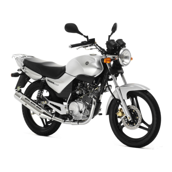
Page 12: Description
DESCRIPTION EAU10410 Left view 1. Headlight (page 6-31) 9. Shift pedal (page 3-4) 2. Fuel cock (page 3-7) 3. Fuse (page 6-30) 4. Battery (page 6-28) 5. Owner’s tool kit (page 6-1) 6. Luggage strap holder (page 3-10) 7. Shock absorber assembly spring preload adjusting ring (page 3-9) 8. -
Page 13: Right View
DESCRIPTION EAU10420 Right view 1. Carrier (page 3-10) 2. Air filter element (page 6-11) 3. Engine oil filler cap (page 6-9) 4. Brake pedal (page 3-5) 5. Kickstarter (page 3-9) 6. Shock absorber assembly spring preload adjusting ring (page 3-9) 7. -
Page 14: Controls And Instruments
DESCRIPTION EAU10430 Controls and instruments 1. Clutch lever (page 3-4) 9. Throttle grip (page 6-13) 2. Left handlebar switches (page 3-3) 10.Fuel tank cap (page 3-5) 3. Main switch/steering lock (page 3-1) 4. Speedometer (page 3-2) 5. Fuel gauge (page 3-3) 6. -
Page 15: Instrument And Control Functions
INSTRUMENT AND CONTROL FUNCTIONS EAU10460 EAU10660 To unlock the steering Main switch/steering lock All electrical systems are off. The key can be removed. EAU10680 LOCK The steering is locked, and all electrical systems are off. The key can be re- moved. -
Page 16: Indicator Lights
INSTRUMENT AND CONTROL FUNCTIONS EAU10980 EAU11080 EAU11630 Indicator lights High beam indicator light “ ” Speedometer unit This indicator light comes on when the high beam of the headlight is switched 1. Left turn signal indicator light “ ” 1. Speedometer 2. -
Page 17: Tachometer
INSTRUMENT AND CONTROL FUNCTIONS EAU11851 EAU37050 EAU12343 Tachometer Fuel gauge Handlebar switches Left 1. Tachometer 1. Fuel gauge 2. Tachometer red zone 2. Red line 1. Dimmer switch “ ” 2. Turn signal switch “ ” The electric tachometer allows the rider The fuel gauge indicates the amount of 3. -
Page 18: Clutch Lever
INSTRUMENT AND CONTROL FUNCTIONS EAU12400 EAU31640 EAU12870 Dimmer switch “ ” Clutch lever Shift pedal Set this switch to “ ” for the high beam and to “ ” for the low beam. EAU12460 Turn signal switch “ ” To signal a right-hand turn, push this switch to “... -
Page 19: Brake Lever
INSTRUMENT AND CONTROL FUNCTIONS EAU12890 EAU12941 EAU13000 Brake lever Brake pedal Fuel tank cap 1. Brake lever 1. Brake pedal 1. Unlock. The brake lever is located at the right The brake pedal is on the right side of To remove the fuel tank cap handlebar grip. -
Page 20: Fuel
Avoid spilling fuel on the hot en- Your Yamaha engine has been de- gine. signed to use regular unleaded gaso- line with a research octane number of 91 or higher. -
Page 21: Catalytic Converter
INSTRUMENT AND CONTROL FUNCTIONS or premium unleaded fuel. Use of un- EAU13431 EAU37210 Catalytic converter Fuel cock leaded fuel will extend spark plug life This model is equipped with a catalytic The fuel cock supplies fuel from the and reduce maintenance costs. converter in the exhaust system. -
Page 22: Starter (Choke) Lever
INSTRUMENT AND CONTROL FUNCTIONS “ON” or “ ” This indicates reserve. If you run out of EAU13590 Starter (choke) lever “ ” fuel while riding, move the lever to this position. Fill the tank at the first oppor- tunity. Be sure to set the lever back to “ON”... -
Page 23: Kickstarter
INSTRUMENT AND CONTROL FUNCTIONS EAU13660 EAU14880 EWA10210 Kickstarter Adjusting the shock absorber WARNING assemblies Always adjust both shock absorber assemblies equally, otherwise poor handling and loss of stability may result. Adjust the spring preload as follows. To increase the spring preload and thereby harden the suspension, turn the adjusting ring on each shock ab- sorber assembly in direction (a). -
Page 24: Carrier
1. Luggage strap holder If a malfunction is noted, have a EWA10170 There are four luggage strap holders Yamaha dealer check the system be- WARNING below the rear of the seat. fore riding. Do not exceed the load limit of 3 kg (6.6 lb) for the carrier. - Page 25 3. Push the start switch. Does the engine start? The neutral switch may be defective. The motorcycle should not be ridden until checked by a Yamaha dealer. 4. Turn the engine off. 5. Shift the transmission into gear. 6. Keep the clutch lever pulled.
-
Page 26: Pre-Operation Checks
PRE-OPERATION CHECKS EAU15591 The condition of a vehicle is the owner’s responsibility. Vital components can start to deteriorate quickly and unexpectedly, even if the vehicle remains unused (for example, as a result of exposure to the elements). Any damage, fluid leakage or loss of tire air pressure could have serious consequences. -
Page 27: Pre-Operation Check List
• Make sure that operation is smooth. • Check cable free play. Throttle grip 6-13, 6-24 • If necessary, have Yamaha dealer adjust cable free play and lubricate cable and grip housing. • Make sure that operation is smooth. Control cables 6-24 •... - Page 28 PRE-OPERATION CHECKS ITEM CHECKS PAGE • Check for damage. • Check tire condition and tread depth. Wheels and tires 6-14, 6-16 • Check air pressure. • Correct if necessary. • Make sure that operation is smooth. Brake and shift pedals 6-24 •...
-
Page 29: Operation And Important Riding Points
6. When the engine is warm, turn the position, the neutral indicator light pletely, it could contact the starter (choke) off. should be on, otherwise have a ground and distract the opera- Yamaha dealer check the electrical cir- tor, resulting in a possible loss cuit. of control. -
Page 30: Starting A Warm Engine
OPERATION AND IMPORTANT RIDING POINTS EAU16640 EAU16671 NOTE: Starting a warm engine Shifting The engine is warm when it responds Follow the same procedure as for start- normally to the throttle with the starter ing a cold engine with the exception (choke) turned off. -
Page 31: Tips For Reducing Fuel Consumption
OPERATION AND IMPORTANT RIDING POINTS ECA10260 EAU16800 EAU16841 Tips for reducing fuel Engine break-in CAUTION: consumption There is never a more important period Even with the transmission in in the life of your engine than the period Fuel consumption depends largely on the neutral position, do not between 0 and 1600 km (1000 mi). -
Page 32: Parking
Never park in an area where there If any engine trouble should oc- are fire hazards such as grass or cur during the engine break-in other flammable materials. period, immediately have a Yamaha dealer check the vehi- cle. -
Page 33: Periodic Maintenance And Minor Repair
If you are not familiar with mainte- certain maintenance work correctly. nance work, have a Yamaha dealer do it for you. NOTE: If you do not have the tools or experi- ence required for a particular job, have a Yamaha dealer perform it for you. -
Page 34: Periodic Maintenance And Lubrication Chart
The annual checks must be performed every year, except if a kilometer-based maintenance is performed in- stead. From 30000 km, repeat the maintenance intervals starting from 6000 km. Items marked with an asterisk should be performed by a Yamaha dealer as they require special tools, data and technical skills. ODOMETER READING (× 1000 km) - Page 35 PERIODIC MAINTENANCE AND MINOR REPAIR ODOMETER READING (× 1000 km) ANNUAL ITEM CHECK OR MAINTENANCE JOB CHECK √ √ √ √ √ √ • Check operation and adjust brake pedal free play. 9 * Rear brake • Replace brake shoes. Whenever worn to the limit √...
- Page 36 PERIODIC MAINTENANCE AND MINOR REPAIR ODOMETER READING (× 1000 km) ANNUAL ITEM CHECK OR MAINTENANCE JOB CHECK • Check starter (choke) operation. √ √ √ √ √ √ 21 * Carburetor • Adjust engine idling speed. • Change. √ √ √...
-
Page 37: Removing And Installing The Cowling And Panels
PERIODIC MAINTENANCE AND MINOR REPAIR EAU18721 Removing and installing the cowling and panels The cowling and panels shown need to be removed to perform some of the maintenance jobs described in this chapter. Refer to this section each time the cowling or a panel needs to be re- moved and installed. - Page 38 PERIODIC MAINTENANCE AND MINOR REPAIR Tightening torque: Carrier bolt: 30 Nm (3.0 m·kgf, 22 ft·lbf) 3. Place the seat in the original posi- tion, and then tighten the bolts. 1. Screw 1. Screw 2. Cowling 2. Pull the front of the panel out, and then slide the panel forward to re- To install the cowling lease it in the rear.
- Page 39 PERIODIC MAINTENANCE AND MINOR REPAIR To install the panel 1. Secure the rear of the panel, and then push the front of the panel in with the key inserted in the lock. 1. Panel lock cover 2. Install the screw. 2.
-
Page 40: Checking The Spark Plug
Do not attempt to diagnose such problems yourself. Instead, have a 2. Clean the surface of the spark plug Yamaha dealer check the vehicle. 1. Spark plug cap gasket and its mating surface, and then wipe off any grime from the 2. -
Page 41: Engine Oil
PERIODIC MAINTENANCE AND MINOR REPAIR 3. Install the spark plug with the EAU37170 Engine oil spark plug wrench, and then tight- The engine oil level should be checked en it to the specified torque. before each ride. In addition, the oil must be changed at the intervals spec- Tightening torque: ified in the periodic maintenance and... - Page 42 PERIODIC MAINTENANCE AND MINOR REPAIR 4. If the engine oil is at or below the 4. Install the engine oil drain bolt, and Make sure that no foreign mate- minimum level mark, add sufficient then tighten it to the specified rial enters the crankcase.
-
Page 43: Cleaning The Air Filter Element
PERIODIC MAINTENANCE AND MINOR REPAIR EAU37120 Cleaning the air filter element The air filter element should be cleaned at the intervals specified in the periodic maintenance and lubrication chart. Clean the air filter element more fre- quently if you are riding in unusually wet or dusty areas. -
Page 44: Adjusting The Carburetor
7. Install the sponge material into the Yamaha dealer, who has the neces- air filter element, and then install sary professional knowledge and expe- the air filter element into the air fil- rience. -
Page 45: Adjusting The Engine Idling Speed
3.0–7.0 mm (0.12–0.28 in) at the crease the engine idling speed, turn the Yamaha dealer make the adjustment. throttle grip. Periodically check the screw in direction (a). To decrease the throttle cable free play and, if neces- engine idling speed, turn the screw in sary, adjust it as follows. -
Page 46: Valve Clearance
(b). from occurring, the valve clearance regarding the specified tires. 3. Tighten the locknut. must be adjusted by a Yamaha dealer at the intervals specified in the periodic Tire air pressure maintenance and lubrication chart. The tire air pressure should be checked and, if necessary, adjusted before each ride. - Page 47 WARNING glass fragments in it, or if the sidewall is Because loading has an enormous cracked, have a Yamaha dealer re- impact on the handling, braking, place the tire immediately. performance and safety characteris- tics of your motorcycle, you should...
-
Page 48: Cast Wheels
If any It is not recommended to patch damage is found, have a Yamaha Front tire: a punctured tube. If unavoid- dealer replace the wheel. Do not Size: 2.75-18 42P... -
Page 49: Adjusting The Clutch Lever Free Play
PERIODIC MAINTENANCE AND MINOR REPAIR Ride conservatively after changing EAU22041 Adjusting the clutch lever free NOTE: a tire since the tire must seat itself If the specified clutch lever free play play on the rim properly. Failure to al- could be obtained as described above, low proper seating may cause tire tighten the locknut and skip the rest of failure, which may result in dam-... -
Page 50: Checking The Front Brake Lever Free Play
Period- ver free play and, if necessary, have a ically check the brake pedal free play Yamaha dealer check the brake sys- and, if necessary, adjust it as follows. tem. To increase the brake pedal free play, EWA10640 turn the adjusting nut in direction (a). -
Page 51: Adjusting The Rear Brake Light Switch
If proper adjustment cannot be on just before braking takes effect. If obtained as described, have a necessary, adjust the brake light switch Yamaha dealer make this ad- as follows. justment. 1. Remove panel A. (See page 6-5.) After adjusting the brake pedal 2. -
Page 52: Checking The Front Brake Pads And Rear Brake Shoes
EAU37000 Checking the front brake pads Checking the front brake fluid touches the brake disc, have a Yamaha and rear brake shoes level dealer replace the brake pads as a set. The front brake pads and the rear brake... -
Page 53: Changing The Brake Fluid
Brake fluid may deteriorate paint- EAU22720 Changing the brake fluid make sure that the top of the mas- ed surfaces or plastic parts. Al- Have a Yamaha dealer change the ter cylinder is level by turning the ways clean spilled... -
Page 54: Drive Chain Slack
PERIODIC MAINTENANCE AND MINOR REPAIR EAU22760 3. To tighten the drive chain, turn the Drive chain slack: Drive chain slack adjusting bolt at each end of the 20.0–30.0 mm (0.79–1.18 in) The drive chain slack should be swingarm in direction (a). To loos- checked before each ride and adjusted 5. -
Page 55: Cleaning And Lubricating The Drive Chain
PERIODIC MAINTENANCE AND MINOR REPAIR ECA10570 EAU23022 ECA11110 Cleaning and lubricating the CAUTION: CAUTION: drive chain Improper drive chain slack will over- Do not use engine oil or any other lu- The drive chain must be cleaned and load the engine as well as other vital bricants for the drive chain, as they lubricated at the intervals specified in parts of the motorcycle and can lead... -
Page 56: Checking And Lubricating The Cables
If a cable is damaged maintenance chart. or does not move smoothly, have a Yamaha dealer check or replace it. Recommended lubricant: Engine oil EWA10720 WARNING... -
Page 57: Checking And Lubricating The Brake And Clutch Levers
PERIODIC MAINTENANCE AND MINOR REPAIR EAU23140 Recommended lubricant: Recommended lubricant: Checking and lubricating the Lithium-soap-based grease (all-pur- Lithium-soap-based grease (all-pur- brake and clutch levers pose grease) pose grease) Brake lever Clutch lever The operation of the brake and clutch levers should be checked before each ride, and the lever pivots should be lu- bricated if necessary. -
Page 58: Checking And Lubricating The Centerstand
2. While applying the front brake, If the centerstand does not move up push down hard on the handlebars and down smoothly, have a Yamaha several times to check if the front dealer check or repair it. fork compresses and rebounds smoothly. -
Page 59: Checking The Steering
Securely support the vehicle so that fork does not operate smoothly, there is no danger of it falling over. have a Yamaha dealer check or re- pair it. 2. Hold the lower ends of the front fork legs and try to move them for- ward and backward. -
Page 60: Checking The Wheel Bearings
Yamaha dealer check tervals specified in the periodic mainte- the wheel bearings. nance and lubrication chart. - Page 61 PERIODIC MAINTENANCE AND MINOR REPAIR working near batteries. In case ECA10610 CAUTION: of contact, administer the fol- lowing FIRST AID. Use only distilled water, as tap water • EXTERNAL: Flush with plenty contains minerals that are harmful of water. to the battery. •...
-
Page 62: Replacing The Fuse
4. If the fuse immediately blows 1. Fuse again, have a Yamaha dealer The fuse holder is located behind panel check the electrical system. B. (See page 6-5.) If the fuse is blown, replace it as fol- lows. -
Page 63: Replacing The Headlight Bulb
PERIODIC MAINTENANCE AND MINOR REPAIR EAU37280 EWA10790 Replacing the headlight bulb WARNING This model is equipped with a quartz Headlight bulbs get very hot. There- bulb headlight. If the headlight bulb fore, keep flammable products away burns out, replace it as follows. from a lit headlight bulb, and do not 1. -
Page 64: Replacing The Tail/Brake Light Bulb
ECA10680 1. Screw CAUTION: 8. Have a Yamaha dealer adjust the 3. Remove the defective bulb by headlight beam if necessary. Do not overtighten the screws, oth- pushing it in and turning it counter- erwise the lens may break. -
Page 65: Replacing A Turn Signal Light Bulb
PERIODIC MAINTENANCE AND MINOR REPAIR EAU24202 EAU37270 Replacing a turn signal light Replacing the auxiliary light bulb bulb 1. Remove the turn signal light lens If the auxiliary light bulb burns out, re- by removing the screw. place it as follows. 1. -
Page 66: Front Wheel
EAU37041 To remove the front wheel EWA10820 WARNING It is advisable to have a Yamaha dealer service the wheel. Securely support the motor- cycle so that there is no danger 1. Rubber cap of it falling over. - Page 67 PERIODIC MAINTENANCE AND MINOR REPAIR 6. While applying the front brake, push down hard on the handlebars several times to check if the front fork compresses and rebounds smoothly. 7. Connect the speedometer cable. 1. Speedometer gear unit 1. Speedometer gear unit retainer 2.
-
Page 68: Rear Wheel
Rear wheel EAU37180 To remove the rear wheel EWA10820 WARNING It is advisable to have a Yamaha dealer service the wheel. Securely support the motor- cycle so that there is no danger 1. Axle nut 1. Brake pedal free play adjusting nut of it falling over. -
Page 69: Troubleshooting
However, should your motorcycle 9. Insert a new cotter pin. EAU37191 To install the rear wheel require any repair, take it to a Yamaha 10. Adjust the brake pedal free play. 1. Install the wheel by inserting the dealer, whose skilled technicians have (See page 6-18.) -
Page 70: Troubleshooting Chart
Remove the spark plug and check the electrodes. The engine does not start. Have a Yamaha dealer check the vehicle. Check the battery. 4. Battery The engine turns over The battery is good. -
Page 71: Motorcycle Care And Storage
MOTORCYCLE CARE AND STORAGE EAU26000 ucts onto seals, gaskets, sprock- cleaning products, solvent or Care ets, the drive chain and wheel thinner, fuel (gasoline), rust re- While the open design of a motorcycle axles. Always rinse the dirt and de- movers or inhibitors, brake flu- reveals the attractiveness of the tech- greaser off with water. - Page 72 MOTORCYCLE CARE AND STORAGE After normal use ECA10790 5. Use spray oil as a universal clean- CAUTION: Remove dirt with warm water, a mild er to remove any remaining dirt. detergent, and a soft, clean sponge, 6. Touch up minor paint damage Do not use warm water since it in- and then rinse thoroughly with clean caused by stones, etc.
-
Page 73: Storage
CAUTION: NOTE: fuel from deteriorating. Storing the motorcycle in a Consult a Yamaha dealer for advice on 5. Perform the following steps to pro- poorly ventilated room or cover- what products to use. tect the cylinder, piston rings, etc. - Page 74 MOTORCYCLE CARE AND STORAGE EWA10950 °C (90 °F)]. For more information WARNING on storing the battery, see page To prevent damage or injury from 6-28. sparking, make sure to ground the NOTE: spark plug electrodes while turning Make any necessary repairs before the engine over.
-
Page 75: Specifications
SPECIFICATIONS Type × quantity: Dimensions: Engine oil: VM22SH x 1 Overall length: Type: Spark plug (s): 1980 mm (78.0 in) SAE10W30 or SAE10W40 or SAE15W40 Overall width: or SAE20W40 or SAE20W50 Manufacturer/model: 745 mm (29.3 in) NGK/CR6HSA Overall height: Spark plug gap: -20 -10 10 20 30 40 50 ˚C 1080 mm (42.5 in) - Page 76 SPECIFICATIONS Chassis: Front: Front suspension: 175 kPa (25 psi) (1.75 kgf/cm²) Frame type: Type: Rear: Diamond Telescopic fork 200 kPa (29 psi) (2.00 kgf/cm²) Caster angle: Spring/shock absorber type: Loading condition: 26.33 ° Coil spring/oil damper 90–200 kg (198–441 lb) Trail: Wheel travel: Front:...
- Page 77 SPECIFICATIONS Rear turn signal light: 12 V, 10.0 W × 2 Auxiliary light: 12 V, 5.0 W × 1 Meter lighting: 12 V, 1.7 W × 4 Neutral indicator light: 14 V, 3.0 W × 1 High beam indicator light: 14 V, 3.0 W ×...
-
Page 78: Consumer Information
Record the key identification number, vehicle identification number and mod- el label information in the spaces pro- vided below for assistance when ordering spare parts from a Yamaha dealer or for reference in case the vehi- cle is stolen. KEY IDENTIFICATION NUMBER: 1. - Page 79 1. Model label The model label is affixed to the frame behind panel B. (See page 6-5.) Record the information on this label in the space provided. This information will be needed when ordering spare parts from a Yamaha dealer.
- Page 80 INDEX Engine oil..........6-9 Periodic maintenance and lubrication Engine, starting a warm......5-2 chart............6-2 Air filter element, cleaning..... 6-11 Pre-operation check list......4-2 Auxiliary light bulb, replacing ....6-33 Front brake lever free play, checking ..........6-18 Rear brake light switch, adjusting ..6-19 Battery...........
- Page 81 INDEX Valve clearance ........6-14 Vehicle identification number....9-1 Wheel bearings, checking ....6-28 Wheel (front) ......... 6-34 Wheel (rear).......... 6-36 Wheels..........6-16...
- Page 84 YAMAHA MOTOR CO., LTD. PRINTED IN CHINA 2005.01-0.3×1 CR...
Need help?
Do you have a question about the YBR125ED and is the answer not in the manual?
Questions and answers