Table of Contents
Advertisement
Quick Links
Advertisement
Chapters
Table of Contents
Troubleshooting

Related Manuals for Yamaha TDR125


Summary of Contents for Yamaha TDR125
- Page 1 OWNER’S MANUAL TDR125 5AE-28199-E3...
- Page 3 EAU00001 Welcome to the Yamaha world of motorcycling! As the owner of a TDR125, you are benefiting from Yamaha’s vast experience in and newest tech- nology for the design and the manufacture of high-quality products, which have earned Yamaha a reputation for dependability.
-
Page 4: Important Manual Information
8 This manual should be considered a permanent part of this motorcycle and should remain with it even if the motorcycle is subsequently sold. 8 Yamaha continually seeks advancements in product design and quality. Therefore, while this manual contains the most current product information available at the time of printing, there may be minor discrepancies between your motorcycle and this manual. - Page 5 IMPORTANT MANUAL INFORMATION EW000002 PLEASE READ THIS MANUAL CAREFULLY AND COMPLETELY BEFORE OPERATING THIS MOTORCYCLE.
- Page 6 EAU00008 TDR125 OWNER’S MANUAL ©1999 by Yamaha Motor Co., Ltd. 1st Edition, August 1999 All rights reserved. Any reprinting or unauthorized use without the written permission of Yamaha Motor Co., Ltd. is expressly prohibited. Printed in Japan...
-
Page 7: Table Of Contents
TABLE OF CONTENTS EAU00009 1 GIVE SAFETY THE RIGHT OF WAY 2 DESCRIPTION 3 INSTRUMENT AND CONTROL FUNCTIONS 4 PRE-OPERATION CHECKS 5 OPERATION AND IMPORTANT RIDING POINTS 6 PERIODIC MAINTENANCE AND MINOR REPAIR 7 MOTORCYCLE CARE AND STORAGE 8 SPECIFICATIONS 9 CONSUMER INFORMATION INDEX... -
Page 9: Give Safety The Right Of Way
GIVE SAFETY THE RIGHT OF GIVE SAFETY THE RIGHT OF WAY ..........1-1... - Page 10 EAU00021 Q GIVE SAFETY THE RIGHT OF WAY Motorcycles are fascinating vehicles, which can give you an unsurpassed feeling of power and free- dom. However, they also impose certain limits, which you must accept; even the best motorcycle does not ignore the laws of physics. Regular care and maintenance are essential for preserving your motorcycle’s value and operating condition.
-
Page 11: Description
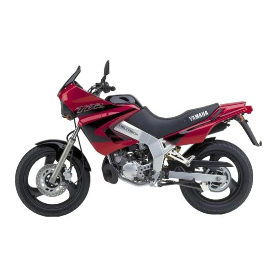
DESCRIPTION Left view .....................2-1 Right view ...................2-2 Controls/Instruments ................2-3... - Page 12 EAU00026 DESCRIPTION Left view 1. Dual headlight (page 3-6) 6. Y.E.I.S. (page 3-15) 2. Fuel cock (page 3-12) 7. Y.P.V.S. (page 3-16) 3. Engine oil tank (page 3-12) 4. Helmet holder (page 3-12) 5. Starter “1” (page 3-13)
- Page 13 DESCRIPTION Right view 8. Tool kit (page 6-1) 14. Rear shock absorber spring 9. Fuse (page 6-32) preload adjusting ring (page 3-14) 10. Air filter (page 6-15) 11. Radiator cap (page 6-11) 12. Rear brake pedal (page 3-9, 6-22) 13. Coolant reservoir tank (page 6-10)
- Page 14 DESCRIPTION Controls/Instruments 15 16 17 18 19 15. Clutch lever (page 3-8, 6-20) 20. Right handlebar switches (page 3-6) 16. Left handlebar switches (page 3-5) 21. Front brake lever (page 3-9, 6-21) 17. Speedometer (page 3-4) 22. Throttle grip (page 6-17) 18.
-
Page 15: Instrument And Control Functions
Fuel tank cap ............3-9 Fuel...............3-10 Catalyzer (for Switzerland and Austria) ....3-11 Two-stroke engine oil ...........3-12 Fuel cock ..............3-12 Starter (choke) “1” ..........3-13 Seat ..............3-13 Helmet holder ............3-14 Rear shock absorber adjustment......3-14 Note on handling of the Yamaha Energy Induction System (Y.E.I.S.) ........3-15... -
Page 16: Main Switch/Steering Lock
EAU00027 INSTRUMENT AND CONTROL FUNCTIONS EW000016 Never turn the key to “OFF” or “LOCK” when the motorcycle is moving. The electrical circuits will be switched off which may result LOCK in loss of control or an accident. PARKING Be sure the motorcycle is stopped before turning the key to “OFF”... -
Page 17: Indicator Lights
INSTRUMENT AND CONTROL FUNCTIONS EAU00063 & ” High beam indicator light “& This indicator comes on when the 5 6 7 8 headlight high beam is used. 0 0 0 EAU01313 Oil level indicator light “ ” ~ 1000r/min km/h This indicator comes on when the oil level is low. -
Page 18: Oil Level Indicator Circuit Check
Oil level indicator light Oil level Oil level indicator light comes on. does not come on. is OK. is low. Engine oil level and Ask a Yamaha dealer Supply engine oil. electrical circuit are OK. to inspect electrical Go ahead with riding. circuit. -
Page 19: Speedometer
INSTRUMENT AND CONTROL FUNCTIONS NOTE: (for German model equipped with speed limiter only) 5 6 7 8 0 0 0 This motorcycle is equipped with a speed limiter which prevents it from exceeding speed ~ 1000r/min km/h 80 km/h. 1. Speedometer 1. -
Page 20: Engine Temperature Gauge
INSTRUMENT AND CONTROL FUNCTIONS EAU00127 Turn signal switch To signal a right-hand turn, push the switch to “6”. To signal a left-hand turn, push the switch to “4”. Once the switch is released it will return to the center position. To cancel the sig- nal, push the switch in after it has returned to the center position. -
Page 21: Headlight Beam Variation
INSTRUMENT AND CONTROL FUNCTIONS EAU00136 Headlight beam variation 3 : High beam light on , 2 : Low beam light on : Auxiliary light on Bulb to be used Left Right Destination France Sweden Portugal Spain & Halogen Greece Belgium Germany 60/55W 60/55W bulb... - Page 22 INSTRUMENT AND CONTROL FUNCTIONS EAU00143 Start switch “, , ” The starter motor cranks the engine when pushing the start switch. EC000005 See starting instructions prior to starting the engine. 1. Engine stop switch 2. Start switch “,” EAU00138 Engine stop switch The engine stop switch is a safety device for use in an emergency such as when the motorcycle overturns or...
-
Page 23: Clutch Lever
INSTRUMENT AND CONTROL FUNCTIONS 1. Clutch lever 1. Shift pedal 1. Front brake lever N. Neutral EAU00152 EAU00158 Clutch lever Front brake lever EAU00157 Shift pedal The clutch lever is located on the left The front brake lever is located on This motorcycle is equipped with a handlebar, and the ignition circuit cut- the right handlebar. -
Page 24: Rear Brake Pedal
INSTRUMENT AND CONTROL FUNCTIONS NOTE: This tank cap cannot be closed unless the key is in the lock. The key cannot be removed if the cap is not locked properly. EW000023 sure properly 1. Rear brake pedal 1. Open installed locked place 2. -
Page 25: Fuel
INSTRUMENT AND CONTROL FUNCTIONS EW000130 Do not overfill the fuel tank. Avoid spilling fuel on the hot engine. Do not fill the fuel tank above the bot- tom of the filler tube or it may overflow when the fuel heats up later and expands. -
Page 26: Catalyzer (For Switzerland And Austria)
INSTRUMENT AND CONTROL FUNCTIONS EAU00191 EAU01084 EC000114 Catalyzer Recommended fuel: (for Switzerland and Austria) The following must be observed to Regular unleaded gasoline This motorcycle is equipped with a prevent a fire hazard or other dam- with a research octane catalytic converter in the exhaust ages. -
Page 27: Two-Stroke Engine Oil
INSTRUMENT AND CONTROL FUNCTIONS OFF: closed position ON: normal position 1. Filler cap 1. Arrow mark pointing to “OFF” 1. Arrow mark pointing to “ON” EAU02956 EAU03050 Two-stroke engine oil Fuel cock With the lever in this position, fuel Make sure the two-stroke engine oil The fuel cock supplies fuel from the flows to the carburetor. -
Page 28: Starter (Choke) "1
INSTRUMENT AND CONTROL FUNCTIONS RES: reserve position 1. Starter(choke) “1” 1. Unlock 1. Arrow mark pointing to “RES” EAU02976 EAU01619 Seat Starter (choke) “1” This indicates reserve. If you run out To remove Starting a cold engine requires a rich- of fuel while riding, move the lever to Insert the key into the lock and turn it er air-fuel mixture. -
Page 29: Helmet Holder
INSTRUMENT AND CONTROL FUNCTIONS 1. Open 1. Adjusting ring 1. Projection 2. Seat holder EAU00260 EAU00295 Helmet holder Rear shock absorber To install To open the helmet holder, insert the adjustment Insert the projection on the front of key in the lock and turn it as shown. This shock absorber is equipped with the seat into the seat holder. -
Page 30: Note On Handling Of The Yamaha Energy Induction System (Y.e.i.s.)
Cylinder in any form can be made. damage will result in poor EC000022 damping performance. 8 8 Take your shock absorber to a Never attempt modify Yamaha dealer for any service. Yamaha Energy Induction System. 3-15... -
Page 31: Yamaha Power Valve System)
The sidestand is ed adjustment. Adjustment should be located on the left side of the frame. left to a Yamaha dealer who has the (Refer to page 5-1 for an explanation professional knowledge and experi- of this system.) ence to do so. -
Page 32: Sidestand/Clutch Switch Operation Check
PULL IN CLUTCH LEVER AND below and if there is any indication PUSH THE START SWITCH. of a malfunction, return the motor- cycle to a Yamaha dealer immedi- ENGINE WILL START. ately for repair. CLUTCH SWITCH IS OK. 3-17... -
Page 33: Pre-Operation Checks
PRE-OPERATION CHECKS Pre-operation check list ..............4-1... -
Page 34: Pre-Operation Check List
EAU01114 PRE-OPERATION CHECKS Owners are personally responsible for their vehicle’s condition. Your motorcycle/scooter’s vital functions can start to deteriorate quickly and unexpectedly, even if it remains unused (for instance, if it is exposed to the elements). Any dam- age, fluid leak or loss of tire pressure could have serious consequences. Therefore, it is very important that, in addition to a thorough visual inspection, you check the following points before each ride. - Page 35 PRE-OPERATION CHECKS ITEM CHECKS PAGE 9 Check for smooth operation. Brake and shift pedal shafts 9 Lubricate if necessary. 6-28 9 Check for smooth operation. Brake and clutch lever pivots 9 Lubricate if necessary. 9 Check for smooth operation. Sidestand pivot 6-28 9 Lubricate if necessary.
-
Page 37: Operation And Important Riding Points
OPERATION AND IMPORTANT RIDING POINTS Starting the engine ................5-1 Starting a warm engine...............5-4 Shifting....................5-4 Recommended shift points (for Switzerland only) ......5-5 Tips for reducing fuel consumption.............5-5 Engine break-in ..................5-5 Parking ....................5-6... -
Page 38: Operation And Important Riding Points
The their functions. Consult engine can be started only under the Yamaha dealer regarding any following conditions: control or function that you do 8 8 The transmission is in neutral. not thoroughly understand. 8 8 The sidestand is up, the trans-... - Page 39 OPERATION AND IMPORTANT RIDING POINTS TURN THE MAIN SWITCH TO “ON” AND THE ENGINE STOP SWITCH TO “#”. IF TRANSMISSION IS IN NEUTRAL IF TRANSMISSION IS IN GEAR AND SIDESTAND IS DOWN, AND SIDESTAND IS UP, PULL IN THE CLUTCH LEVER AND PUSH PUSH THE START SWITCH.
- Page 40 7. After the engine is warm, turn off on. If the light does not come on, ask the starter (choke) completely. EC000034 a Yamaha dealer to inspect it. NOTE: The oil level indicator light should The engine is warm when it responds 4.
-
Page 41: Starting A Warm Engine
OPERATION AND IMPORTANT RIDING POINTS EAU01258 EC000048 Starting a warm engine The starter (choke) is not required 8 8 Do not coast for long periods when the engine is warm. with the engine off, and do not EC000046 tow the motorcycle a long dis- tance. -
Page 42: Recommended Shift Points (For Switzerland Only)
OPERATION AND IMPORTANT RIDING POINTS EAU02937 EAU00424 EAU00436 Engine break-in Recommended shift points Tips for reducing fuel There is never a more important peri- (for Switzerland only) consumption od in the life of your motorcycle than The recommended shift points are Your motorcycle’s fuel consumption the period between zero and 1,000 shown in the table below. -
Page 43: Parking
The exhaust system is hot. Park 500 ~ 1,000 km od, consult a Yamaha dealer the motorcycle in a place where Avoid prolonged operation above immediately. pedestrians or children are not 7,000 r/min. -
Page 45: Periodic Maintenance And Minor Repair
PERIODIC MAINTENANCE AND MINOR REPAIR Tool kit ..............6-1 Drive chain lubrication..........6-25 Periodic maintenance and lubrication ....6-3 Cable inspection and lubrication ......6-25 Cowling and panel removal and installation...6-6 Throttle cable and grip lubrication......6-26 Cowling A, B ............6-7 Autolube pump adjustment ........6-26 Panel A ..............6-7 Brake and shift pedal lubrication......6-26 Spark plug inspection..........6-8... -
Page 46: Periodic Maintenance And Minor Repair
Safety is an obligation done by a Yamaha dealer. of the motorcycle owner. The mainte- nance and lubrication schedule chart should be considered strictly as a guide to general maintenance and lubrication intervals. - Page 47 PERIODIC MAINTENANCE AND MINOR REPAIR NOTE: If you do not have necessary tools required during a service operation, take your motorcycle to a Yamaha dealer for service. EW000063 Modifications to this motorcycle not approved by Yamaha may cause loss of performance, and render it unsafe for use.
-
Page 48: Periodic Maintenance And Lubrication
PERIODIC MAINTENANCE AND MINOR REPAIR EAU00473 PERIODIC MAINTENANCE AND LUBRICATION EVERY 6,000 km 12,000 km ITEM CHECKS AND MAINTENANCE JOBS Initial 6 months 12 months (1,000 km) (Whichever (Whichever comes first) comes first) 9 Check fuel hoses for cracks or damage. 1 * Fuel line 9 Replace if necessary. - Page 49 PERIODIC MAINTENANCE AND MINOR REPAIR EVERY 6,000 km 12,000 km ITEM CHECKS AND MAINTENANCE JOBS Initial 6 months 12 months (1,000 km) (Whichever (Whichever comes first) comes first) 9 Check swingarm pivoting point for play. 9 Correct if necessary. 10 * Swingarm 9 Lubricate with lithium soap base grease every 24,000 km or 24 months (whichever comes first).
- Page 50 22 * Cooling system 9 Change coolant every 24,000 km or 24 months (whichever comes first). * Since these items require special tools, data and technical skills, they should be serviced by a Yamaha dealer. EAU02970 NOTE 8 The air filter needs more frequent service if you are riding in unusually wet or dusty areas.
-
Page 51: Cowling And Panel Removal And Installation
PERIODIC MAINTENANCE AND MINOR REPAIR 1. Cowling A 1. Cowling B 1. Panel A EAU01139 Cowling and panel removal and installation The cowlings and panels illustrated need to be removed to perform some of the maintenance described in this chapter. Refer to this section each time a cowling or panel has to be removed or reinstalled. -
Page 52: Cowling A, B
PERIODIC MAINTENANCE AND MINOR REPAIR 1. Radiator cover 1. Screw ( 10) 1. Screw ( 2) 2. Screw ( 2) 2. Panel A 3. Remove the screws and pull out- EAU01088 EAU01691 Cowling A, B ward on the areas shown. Panel A To remove To remove... -
Page 53: Spark Plug Inspection
1/4 sive, the spark plug should be a Yamaha dealer. The condition of to 1/2 turn past finger tight. The spark replaced with the specified plug. the spark plug can indicate the condi- plug should be tightened to the speci- tion of the engine. -
Page 54: Transmission Oil
PERIODIC MAINTENANCE AND MINOR REPAIR 2. With the engine stopped, check the oil level through the level window located at the right side crankcase cover. NOTE: Wait a few minutes until the oil level settles before checking. 1. Level window 1. -
Page 55: Cooling System
PERIODIC MAINTENANCE AND MINOR REPAIR Recommended oil: See page 8-1 Oil quantity: Total amount: 0.8 L Periodic oil change: 0.75 L EC000078 8 8 Do not put in any chemical 1. Drain bolt 1. Maximum level mark additives. Transmission 2. Minimum level mark 3. -
Page 56: Changing The Coolant
PERIODIC MAINTENANCE AND MINOR REPAIR EW000067 EAU01622* Changing the coolant 1. Put the motorcycle on a level Do not remove the radiator cap place. when the engine is hot. 2. Remove the seat (See page 3-13 for seat removal proce- EC000080 dures.) 3. - Page 57 PERIODIC MAINTENANCE AND MINOR REPAIR 9. Install the reservoir tank hose. 10. Pour the recommended coolant into the radiator until it is full. Recommended antifreeze: High quality ethylene glycol antifreeze containing corrosion inhibitors for aluminum engines 1. Drain bolt 1. Reservoir tank hose Antifreeze and water mixing ratio: 5.
-
Page 58: Air Filter
NOTE: 2. Remove cowling A and B. (See If any leakage is found, ask a page 6-7 for cowling removal Yamaha dealer to inspect the cooling and installation steps.) sytem. 3. Remove the fuel tank bolt. 4. Lift the front of the fuel tank 15. - Page 59 PERIODIC MAINTENANCE AND MINOR REPAIR EW000071 8 8 Support the fuel tank carefully during this procedure. 8 8 Do not tilt the fuel tank too much or pull it too hard because the fuel hose connec- tions may become loose caus- ing fuel leakage.
-
Page 60: Carburetor Adjustment
8 8 Make sure the air filter is prop- engine and requires very sophisticat- erly seated in the air filter ed adjustment. Most adjustments case. should be left to a Yamaha dealer 8 8 The engine should never be who has the professional knowledge without filter and experience to do so. -
Page 61: Throttle Cable Free Play Adjustment
1,300 ~ 1,500 r/min 1,400 ~ 1,500 r/min (A, CH only) NOTE: If the specified idle speed cannot be obtained by performing the above adjustment, consult a Yamaha deal- a. Free play 1. Locknut 2. Adjusting nut EAU00634 Throttle cable free play 1. -
Page 62: Tires
PERIODIC MAINTENANCE AND MINOR REPAIR EAU00647 EW000083 180 kg Tires Maximum load* 179 kg (CH, A) To ensure maximum performance, Proper loading of your motorcycle Cold tire pressure Front Rear long service, and safe operation, note 175 kPa 200 kPa is important for several character- the following: Up to 90 kg load*... - Page 63 130/80-17 65P TW54 immediately. Brakes, tires, and DUNLOP 130/80-17 65P D602 related wheel parts replacement 1. Tread depth should be left to a Yamaha Service Minimum tire tread 2. Side wall depth 0.8 mm Technician. (front and rear) Tire inspection...
-
Page 64: Wheels
Check for cracks, bends, or warpage of the wheels. If any abnormal condition exists in a wheel, consult a Yamaha 1. Locknut 1. Locknut dealer. Do not attempt even 2. Adjusting bolt 2. Adjusting nut 3. -
Page 65: Front Brake Lever Free Play Adjustment
23 mm below the top of should be 2 ~ 5 mm. accident. Have a Yamaha the footrest. If not, ask a Yamaha 1. Loosen the locknut. dealer inspect and bleed the dealer to adjust it. 2. Turn the adjusting bolt in direc- system if necessary. -
Page 66: Brake Light Switch Adjustment
2. Adjusting nut can result in loss of control and an EAU00721 EAU00713 Checking the front and rear accident. Have a Yamaha dealer Brake light switch brake pads inspect and bleed the system if adjustment EAU00725 necessary. -
Page 67: Inspecting The Brake Fluid Level
If the thickness is less than the speci- formance. causing the brakes to become inef- fied value, have a Yamaha dealer fective. Recommended fluid: replace the pads. Before riding, check that the brake... -
Page 68: Brake Fluid Replacement
Mixing fluids may result in a The brake fluid should be replaced harmful chemical reaction and only by trained Yamaha service per- lead to poor brake performance. sonnel. Have the Yamaha dealer 8 Be careful that water does not... -
Page 69: Drive Chain Slack Adjustment
PERIODIC MAINTENANCE AND MINOR REPAIR To check the chain slack the motor- Turn each adjusting nut exactly cycle must be held straight up with the same amount to maintain both wheels on the ground and with- correct axle alignment. There are out rider. -
Page 70: Drive Chain Lubrication
If a cable does not operate smoothly, kerosene to clean the drive chain. ask a Yamaha dealer to replace it. Wipe it dry, and thoroughly lubricate it Recommended lubricant: with SAE 30 ~ 50W motor oil. Do not... -
Page 71: Autolube Pump Adjustment
Lubricate the pivoting parts. Lubricate the pivoting parts. cated adjustment. Recommended lubricant: Recommended lubricant: Adjusting should be left to a Yamaha Engine oil Engine oil dealer who has the professional knowledge and experience to do so. 6-26... -
Page 72: Sidestand Lubrication
Engine oil EW000113 EAU02939 Front fork inspection If the sidestand does not move Visual check smoothly, consult a Yamaha deal- EW000115 Securely support the motorcycle so there is no danger of it falling over. Check for scratches or damage on the inner tube and excessive oil leak- age from the front fork. -
Page 73: Steering Inspection
Hold the lower end of the front forks and try to move them forward and backward. If any free play can be felt, ask a Yamaha dealer to inspect and adjust the steering. Inspection is eas- ier if the front wheel is removed. -
Page 74: Wheel Bearings
Battery electrolyte is poisonous wheel hub or if the wheel does not sealed-type battery. Therefore it is and dangerous, causing severe turn smoothly, have a Yamaha dealer not necessary to check the elec- burns, etc. It contains sulfuric inspect the wheel bearings. -
Page 75: Fuse Replacement
Yamaha dealer. 8 8 Always make sure the connec- ates. If the fuse immediately blows again, consult a Yamaha dealer. tions are correct when rein- stalling the battery. 6-30... -
Page 76: Headlight Bulb Replacement
4. Remove the defective bulb. 2. Disconnect the headlight con- If the headlight beam adjustment EW000119 nector and remove the bulb hold- is necessary, ask a Yamaha er cover. dealer to make adjustment. Keep flammable products and your 3. Remove the bulb holder. -
Page 77: Taillight Bulb Replacement
PERIODIC MAINTENANCE AND MINOR REPAIR 1. Screw ( 2) 1. Socket 1. Lens 2. Panel A 2. Screw 4. To remove the defective bulb, EAU01095 EAU01078 Turn signal light bulb turn it counterclockwise. Taillight bulb replacement replacement 5. Push a new bulb into the socket 1. -
Page 78: Front Wheel Removal
3. Elevate the front wheel by plac- screw. 8 8 It is advisable to have a ing a suitable stand under the Yamaha dealer service the engine. wheel. 4. Remove the wheel axle and the 8 8 Securely support the motorcy- front wheel. -
Page 79: Front Wheel Installation
5. Tighten the wheel axle to the 8 8 It is advisable to have a installed with the projections specified torque. Yamaha dealer service the meshed into the slots. 6. Install the pinch bolt and tighten wheel. 2. Lift up the wheel between the it to the specified torque. -
Page 80: Rear Wheel Installation
PERIODIC MAINTENANCE AND MINOR REPAIR NOTE: 8 Do not depress the brake pedal when the disc and caliper are separated. 8 You do not have to disassemble the chain in order to remove or install the rear wheel. EAU01620 2. Elevate the rear wheel by placing Rear wheel installation suitable stand... -
Page 81: Troubleshooting
If your motorcycle requires any repair, bring it to a Yamaha dealer. The skilled technicians at a Yamaha dealership have the tools, experi- ence, and know-how to properly ser- vice your motorcycle. Use only gen-... -
Page 82: Troubleshooting Chart
2. Compression There is compression. Go to ignition check. Use electric starter. No compression. Ask a Yamaha dealer to inspect. 3. Ignition Wipe clean with dry cloth and correct Open throttle half-way and start Wet. Remove spark spark gap or replace spark plug. -
Page 83: Engine Overheating
Restart the engine. If the engine overheats again, ask a Level is OK. Yamaha dealer to inspect and repair the cooling system. NOTE: If it is difficult to get the recommended coolant, tap water can be temporarily used, provided that it is changed to the rec- ommended coolant as soon as possible. -
Page 85: Motorcycle Care And Storage
MOTORCYCLE CARE AND STORAGE Care....................7-1 Storage ....................7-4... -
Page 86: Motorcycle Care And Storage
EAU01518 MOTORCYCLE CARE AND STORAGE Before cleaning Cleaning Care 1. Cover up the muffler outlet with a After normal use exposure technology plastic bag. Remove dirt with warm water, a neu- makes a motorcycle charming but 2. Make sure that all caps and cov- tral detergent and a soft clean also vulnerable. - Page 87 MOTORCYCLE CARE AND STORAGE 8 8 Improper cleaning can damage 8 8 Do high-pressure After riding in the rain, near the sea windshields, cowlings, panels washers or steam-jet cleaners or on salt-sprayed roads and other plastic parts. Use since they cause water seep- Since sea salt or salt sprayed on the only a soft, clean cloth or age and deterioration in the...
- Page 88 After cleaning NOTE: 1. Dry motorcycle with Consult a Yamaha dealer for advice Make sure that there is no oil or chamois or an absorbing cloth. on what products to use. wax on the brakes and tires. If 2. Immediately dry the drive chain...
- Page 89 MOTORCYCLE CARE AND STORAGE Long-term a. Remove the spark plug cap and Storage Before storing your motorcycle for spark plug. Short-term several months: b. Pour a teaspoonful of engine oil Always store your motorcycle in a 1. Follow all the instructions in the into the spark plug bore.
- Page 90 MOTORCYCLE CARE AND STORAGE Lubricate all control cables and 9. Remove the battery and fully the pivoting points of all levers charge it. Store it in a cool, dry and pedals as well as of the place and recharge it once a sidestand/centerstand.
-
Page 91: Specifications
SPECIFICATIONS Specifications ..................8-1 How to use the conversion table ............8-5... - Page 92 SPECIFICATIONS SPECIFICATIONS Specifications Model TDR125 Engine oil (2-cycle) Dimensions Type Yamaha oil 2T or equivalent 2-stroke engine oil Overall length 2,120 mm (F, GB, IRL, B, P, GR, E) Capacity 2,185 mm (S, SF, D, CH, A) Total amount 1.2 L...
- Page 93 SPECIFICATIONS Spark plug Tire Type/Manufacturer BR9ES/NGK Type Tubeless Spark plug gap 0.7 ~ 0.8 mm Front Clutch type Wet, multiple-disc Size 100/90-18 56P Transmission Manufacturer/ BRIDGESTONE/TW53 model DUNLOP/D602F Primary reduction system Helical gear Rear Primary reduction ratio 71/22 (3.227) Size 130/80-17 65P Secondary reduction system Chain drive...
- Page 94 SPECIFICATIONS Wheels Shock absorber Front Front Type Cast wheel Type Coil spring/oil damper Size MT2.15 Rear Rear Type Coil-gas spring/oil damper Type Cast wheel Wheel travel Size MT2.50 Front 180 mm Brakes Rear 180 mm Front Electrical Type Single disc brake Ignition system C.D.I.
- Page 95 SPECIFICATIONS Stop/tail light 12 V, 21/5W Front flasher light 12 V, 21W Rear flasher light 12 V, 21W Auxiliary light 12 V, 4W 12 V, 3.4W 2 (GB, IRL only) Meter light 12 V, 3.4W Neutral indicator light 12 V, 3.4W High beam indicator light 12 V, 3.4W Oil level indicator light...
-
Page 96: How To Use The Conversion Table
SPECIFICATIONS CONVERSION TABLE EAU01064 HOW TO USE THE CONVERSION TABLE METRIC TO IMPERIAL All specification data in this manual are listed in SI and Metric unit Multiplier Imperial unit METRIC UNITS. m • kg 7.233 ft• lb m • kg 86.794 in•... -
Page 97: Consumer Information
CONSUMER INFORMATION Identification number records .............9-1 Key identification number ..............9-1 Vehicle identification number..............9-1 Model label ..................9-2... -
Page 98: Consumer Information
Record the key identification number, vehicle identification number and model label information in the spaces provided for assistance when order- ing spare parts from a Yamaha deal- er or for reference in case the vehicle is stolen. 1. Key identification number 1. -
Page 99: Model Label
The model label is affixed to the frame under the seat. (See page 3-13 for seat removal procedures.) Record the information on this label in the space provided. This informa- tion will be needed to order spare parts from your Yamaha dealer. -
Page 100: Left View
Fuse replacement........6-30 Catalyzer Neutral indicator light.......3-2 (for Switzerland and Austria) ....3-11 Handlebar switches .........3-5 Note on handling of the Yamaha Checking the front and rear brake Dimmer switch ........3-5 Energy Induction System (Y.E.I.S.) ..3-15 pads ............6-21 Engine stop switch ........3-7 Clutch lever ..........3-8... -
Page 101: Right View
Wheel bearings ........6-29 Shifting ............5-4 Wheels ..........6-19 Sidestand ..........3-16 Sidestand lubrication ......6-27 Y.P.V.S. Sidestand/clutch switch operation (Yamaha Power Valve System) ..3-16 check ..........3-17 Spark plug inspection ......6-8 Specifications ..........8-1 Speedometer...........3-4 Start switch..........3-7 Starter (choke) “1” .......3-13 Starting a warm engine ......5-4 Starting the engine ........5-1... - Page 104 YAMAHA MOTOR CO., LTD. PRINTED ON RECYCLED PAPER PRINTED IN JAPAN 99·8–0.1 1(E)
Need help?
Do you have a question about the TDR125 and is the answer not in the manual?
Questions and answers