
Related Manuals for Fortec Star Lifetime


Summary of Contents for Fortec Star Lifetime
- Page 1 (English) Lifetime Digital Satellite Receiver...
-
Page 2: Table Of Contents
CONTENTS PREFACE OVERVIEW 1. How to use the REMOTE CONTROL KEY 2. FRONT PANEL 3. REAR PANEL 4. CONNECTION DIAGRAM 5. CONNECTION DIAGRAM (DISH) OPERATION 1. Start Up 2. Main Menu 3. User Setup 4. Installation 5. Channel Edit 6. System Setup 7. -
Page 3: Preface
PREFACE General Information Congratulations on purchasing a new Fortec Star digital satellite receiver. Before using your new receiver, we suggest that you read this manual carefully for your own safety, and to learn how to correctly operation the system. Main Features •... - Page 4 PREFACE FOR YOUR SAFETY • Do not open the cover. It may cause malfunction or electric shock. • When not in use for a long period of time, please unplug the receiver from the power outlet. Also do not use a damaged power cord that may cause fire or electric shock. •...
-
Page 5: Overview
OVERVIEW 1. How to use the REMOTE CONTROL Function Turns the receiver on/off. In the standby mode, it will automatically changed to the TV POWER Mode which enables watching terrestrial TV broadcasting. Sound Off/On. MUTE Shows channel information, such as channel number, channel name, Frequency, Polarity, Symbol Rate, INFO... - Page 6 OVERVIEW 1 Operating Principle • Select an item by using the up and down keys and change the value of the highlighted (selected) item by using keys shown on the screen. Press the OK key to enter the sub-menu if there is no instruction marked on the screen. •...
-
Page 7: Front Panel
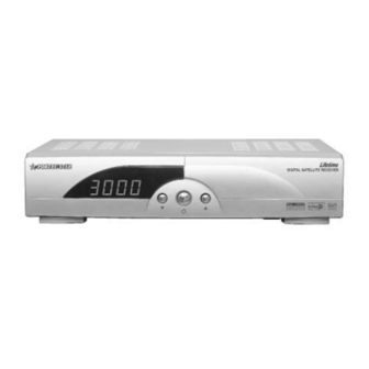
OVERVIEW 2. FRONT PANEL Figure 2-2 Front Panel 1. POWER Switches between Stand-by mode and normal mode (On/Off). 2. CH ▲, CH ▼ Changes Channel Up/Down 3. CHANNEL DISPLAY (4 digit / 7 Segment) After pressing the power button, “ON” is showed on screen . After the receiver searches the program, the program number is displayed as “0001~3000”. -
Page 8: Rear Panel
OVERVIEW 3. REAR PANEL NAME FUNCTION IF INPUT IF INPUT from LNB to receiver IF OUTPUT IF Loop-through output to 2 receiver ANT IN Input from terrestrial TV antenna or cable TV OUT Output to TV VIDEO Composite video output (RCA jack) Left audio output (RCA jack) Right audio output (RCA jack) S/P DIF... -
Page 9: Connection Diagram
OVERVIEW 1 4. CONNECTION DIAGRAM 1) Receiver to TV with RF output and terrestrial antenna: Connect the TV antenna to the ANT IN socket of the receiver. Connect the TV out of the receiver to the RF INPUT of the TV set. Search on the TV set for UHF Channel 38 (for Europe), or channel VHF channel 3 or 4 for North America. - Page 10 OVERVIEW 3) Receiver to TV with Audio and Video cables: Connect the TV antenna to the ANT IN socket of the receiver if a Terrestrial antenna also needs to be connected. Connect the TV out socket of the receiver to the RF IN of the TV set. This connection is not necessary if the Video RCA connection is used in the next step.
-
Page 11: Connection Diagram (Dish)
OVERVIEW 1 5. CONNECTION DIAGRAM (DISH) 1) One dish: 2) 2 dishes with 0/12V switch (0/12V jack not available on North American model):... - Page 12 OVERVIEW 1 3) Two dishes using DiSEqC mode:...
-
Page 13: Operation 2
OPERATION 2 1. Start Up If you are watching TV through the RF-cable, you need to adjust the Channel number. The type of TV and Channel number are set to PAL-G and Channel 38 (for Europe), or to NTSC and Channel 3 (for North America) at the factory. 1.1 Language Select the desired language and press OK to confirm it. -
Page 14: User Setup
OPERATION 3. User Setup In the USER SETUP mode, you can select the sub-mode as shown in the right figure by pressing the CH ▲▼key and then selecting the OK key. Any changes are stored by pressing the EXIT key. 3.1 Language Press EXIT or the OK key after you select your preferred language by using the VOL ◄►... - Page 15 OPERATION 2 3.5 Modulator You may need to change the modulator setting to support your program source: 1) PAL-G, PAL-I, PAL-K, NTSC is supported. 2) Modulator channel can be changed from channel 21 to channel 69 for PAL, and from 3 to 4 for NTSC. 3.6 OSD setting You can adjust the transparency level by using the Vol◄►keys.
-
Page 16: Installation
4.1.2 LNB type • Select proper LNB type using ◄►keys according to the LNB type you are using. The default settings are the Fortec Star Universal LNB (Universal 1). All settings for the LNB type are shown below: o Universal 1 (975MHz & 10600 MHz) o Universal 2 (975MHz &... - Page 17 OPERATION • Option DiSEqC box If the option switch is used according to figure below, there are two different ways to scan the satellites depending on LNB type. (1) For universal LNB: Select a DiSEqC number to which the RF signal is fed the LNB. (2) For standard LNB: For low band scanning, “set 22kHz”...
- Page 18 OPERATION 4.1.6 LNB POWER Set the LNB power On/Off by using ◄►keys. 4.1.7 0/12V (Not available on the North American model) By turning this function On or Off, the receiver will either supply or not supply 12V from this terminal using ◄►keys. 4.1.8 TP Select a specific transponder by using the VOL ◄►keys.
- Page 19 OPERATION 2 2) USALS (DiSEqC 1.3) (1) Satellite Position: It indicates the position for the saved satellite. You can change the position of the satellite by using the numeric keys. (2) My Longitude: Input Local Longitude by using the numeric keys. (3) My latitude: Input Local Latitude by using the numeric keys.
- Page 20 OPERATION 2 4.3 TP Scan The selected transponders are scanned in this menu. 1) Select TP scan in the installation menu. 2) Select a satellite by using the ◄►keys. 3) Select the scan mode FTA or ALL. 3) Scroll through the TP list by using the ▲▼key, and select the desired TPs by using the ◄►keys, then press OK to start the search.
- Page 21 OPERATION 2 4.6 Edit TP/Satellite In this mode, you can add new, edit or delete satellite and transponder information. 4.6.1 How to add a new satellite • Select “New”. It is located at the bottom of satellite name list. Enter the new satellite name by using the numeric keys, ▲▼...
-
Page 22: Channel Edit
OPERATION 2 4.6.5 How to delete or edit a transponder • Press OK key after selecting a satellite. • Select Edit TP, then the transponder list will appear. • Scroll through the list of transponders. • Press OK to select the TP you want to Edit or Delete. - Page 23 OPERATION 5.3 How to delete the channel 1) Select “Delete” and press OK. 2) Select a channel you want to delete by using the ◄►key. More than one channel can be selected. 3) Press the OK key after selecting all the channels to be deleted. 5.4 How to store channels in a Favorite List 1) Select “Favorite”...
-
Page 24: System Setup
OPERATION 6. Systems Setup 6.1 Parental Control The factory set default Password is “0-0-0-0”. 6.1.1 Change PIN Code You can change the PIN Code (Password), if you want to. 1) Enter the Old password. If you enter this mode for the first time after purchasing the receiver, the OLD PIN Code is the default password. - Page 25 OPERATION 2 3) In the Code Mode, you are transferring the “main” s/w” from the STB (Master) receiver to the STB (Slave) receiver. To start the transfer, you must press the “Channel Up” key on the Front panel of STB (Master), not STB (Slave). 4) In the Data Mode, you are transferring the “main”...
-
Page 26: Channel List
OPERATION 7. View the Channel List While Watching TV • You can see the channel list as shown in the figure to the right by pressing the OK key. • You can view the channels alphabetically by pressing the MENU key. •... -
Page 27: How To Download Software Via Rs-232 Serial Cable
1) Connect between Receiver and PC by RS-232 Female-to Female Nul Modem Cable. The PIN configuration is shown below. 2) Please go to the Fortec Star Web site to get the Uploader software and the software available for this receiver. The Uploader program is illustrated below. -
Page 28: Specifications
SPECIFICATIONS Tuner/LNB RF Modulator Input Connector F-type, IEC 169-24 Connector IEC 169-2 IF Input Frequency 950MHz to 2150MHz Male/Female IF Loop throughout 950MHz to 2150MHz Frequency 470 MHz to 860 MHz IF Frequency Zero-IF Output Channel CH 21-69 or Ch 3 -4 Input Level -65dBm~ -25Bm TV Standard... - Page 29 TROBLE SHOOTING Problem Possible Causes Remedy LED on front AC power cord disconnected Connect power cord properly panel does not into the power socket light up No picture or Wrong connection of the video/audio Connect two terminals sound output to TV input terminal correctly with SCART cable or RCA or RF cable.
Need help?
Do you have a question about the Lifetime and is the answer not in the manual?
Questions and answers