Table of Contents
Advertisement
Advertisement
Table of Contents
Troubleshooting

Related Manuals for CognitiveTPG C series


Summary of Contents for CognitiveTPG C series
- Page 1 Cxi and Ci Printers USER’S MANUAL CXI-UGML001-EN...
- Page 2 Copyright © 2011, CognitiveTPG, Inc. CognitiveTPG™, Cxi™, Ci™, and Compact Industrial™ are trademarks of CognitiveTPG. Microsoft® and Windows™ are trademarks of Microsoft Corporation. Other product and corporate names used in this document may be trademarks or registered trademarks of other companies, and are used only for explanation and to their owner’s benefit, without intent to infringe.
-
Page 3: Table Of Contents
Table of Contents Chapter 1: Welcome ������������������������������������������������������������������������ 1 Chapter 2: Getting Started������������������������������������������������������������� 2 Outside the Printer ....................... 2 Inside the Printer ......................3 Connection Ports and Power Connector .............. 4 Setting Up the Cxi and Ci Printers ................9 Chapter 3: Software Installation ������������������������������������������������� 35 Chapter 4: Using the Administrator Tool ������������������������������������... - Page 4 Chapter 8: Troubleshooting ��������������������������������������������������������� 59 Isolating Problems ......................59 Common Issues ......................60 General Troubleshooting Tips ................62 Chapter 9: Printer Specifications ������������������������������������������������� 64 Standard Features .......................64 Optional Features .......................64 Printing Specifications ....................65 Media Specifications ....................65 Ribbon Specifications ....................66 Font Specifications .....................66 Bar Code Symbologies and Specifications ............66 Cognitive Programming Language (CPL) ............67 Communications Specifications ................67 Electrical Specifications ....................67...
-
Page 5: Chapter 1: Welcome
A printed copy of this document is provided with every C Series printer. Chapter 2 of this User’s Manual provides further instructions on setting up your Cxi and Ci printers. -
Page 6: Chapter 2: Getting Started
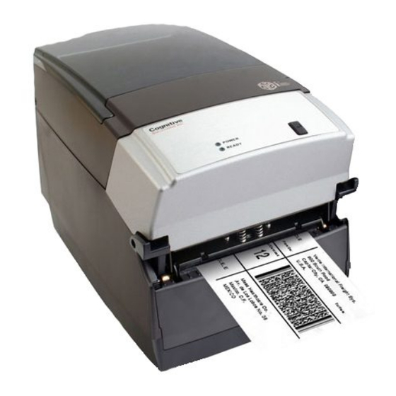
Chapter 2: Getting Started First, take a tour around the printer to understand its parts and functions. Outside the Printer Figure 2-1. C Series Top and Front View Device A – LCD control panel (Cxi only) Back-lit, two-line, 16-character display with full menus to change setup options B –... -
Page 7: Inside The Printer
Contains user interface buttons D – Printhead Printing mechanism E – Printhead bracket Holds the printhead F – Ribbon drive gears Feeds ribbon through the printer Paper Media Guide Bar Figure 2-3. C Series Inner Side View of Media Bar... -
Page 8: Connection Ports And Power Connector
Chapter 2: Getting Started Figure 2-4. C Series Top View of Media Guide from Behind Printer Device A – Media guide (silver bar) Guides the labels through the printer Connection Ports and Power Connector Figure 2-5. C Series Connections and Power (Back View) Connector A –... - Page 9 Chapter 2: Getting Started Take Up Spindle and Take Up Clutch (Gears) Figure 2-6. Take Up Spindle, Clutch, and Side view of Clutch Gears Components Description Take Up Spindle Take Up Clutch Supply Spindle and Supply Clutch Figure 2-7. Supply Spindle and Clutch Components Description Supply Spindle...
- Page 10 Chapter 2: Getting Started Printhead Assembly (TPH, Shield, Bracket, and LED Array) Figure 2-8. Printhead Assembly Components Description Printhead Bracket LED Array Shield Platen and Index Sensor Figure 2-9. Platen Assembly and Index Sensor Components Description Index Sensor Platen...
- Page 11 Chapter 2: Getting Started Understanding the Control Panel Buttons and LCD (Cxi Only) When the printer is powered on, the LCD displays COGNITIVE CXI. After approximately 2 seconds, the LCD displays COGNITIVE. This is an indication that the menu is at its highest level.
- Page 12 Chapter 2: Getting Started Understanding the LCD Menu Structure MAIN MENU USER MENU LCD Contrast Contrast 0 … 8 Backlight Control ON or OFF Language Menu English, Spanish, French, Russian Beeper Volume Volume 0 … 3 Set Date and Time Date (MM/DD/YY) Time (HH:MM:SS) SETUP MENU...
-
Page 13: Setting Up The Cxi And Ci Printers
Chapter 2: Getting Started Setting Up the Cxi and Ci Printers Setting up a C Series printer is an easy process. This chapter describes printer requirements, printer controls, loading thermal transfer ribbon, and loading print media. The printer self test is also described. Be sure to follow all steps in sequential order as listed in this User’s Manual to avoid electric shock or damage to the C Series printer. - Page 14 Chapter 2: Getting Started Controls, Indicators, and Connectors Controls and indicators for the C Series printer are located on the front panel and right side of the printer. Cxi printers also have an LCD display on the user interface. Figure 2-12. C Series Printer Controls and Indicators...
- Page 15 The USB flash drive can be used upgrade printer firmware. This topic is discussed further in Chapter 5 “USB-A Host. ” Connecting Power to the Printer The next step is to provide power to the C Series printer. Use only the AC adapter...
- Page 16 Connect the power supply cord into the power connector located in the back corner of the C Series printer. The flat end of the power supply cord, listed as B below in Figure 2-15, has an arrow to indicate which end is on top. There is also an indented key, shown as A below in Figure 2-15, to illustrate which end should be inserted upright into the C Series power connector.
- Page 17 NOTE: THE POWER LIGHT ON THE TOP USER INTERFACE COVER TURNS GREEN TO INDICATE THE UNIT IS RECEIVING POWER. THE READY LIGHT FIRST TURNS RED, THEN AUBURN, THEN GREEN WHEN THE PRINTER IS READY TO PRINT. Figure 2-17: Powering ON the C Series Printer Device Primary Function A - POWER light Shows power status ON –...
- Page 18 NOTE: POWER OFF THE PRINTER BEFORE PROCEEDING. Thermal Transfer Ribbon Loading (TT Printers Only) To run the C Series printers in thermal transfer mode, a ribbon must be loaded properly into the C Series printer in order to print. This section details step-by-step instructions on how to load thermal transfer ribbon into the printer.
- Page 19 Chapter 2: Getting Started Figure 2-21. Removing the Test Sample from the Printer Place sample ribbon provided with printer in front of printer. Place large media end towards printer with small take up roll end facing away from printer as shown in Fig. 2-22 below.
- Page 20 Chapter 2: Getting Started Figure 2-24. Unlatching the Printhead Mechanism Next, raise the printhead mechanism fully. Refer to the figure below. Figure 2-25. Fully Raised Printhead Mechanism CLEANING NOTE: THIS IS THE IDEAL POSITION FOR CLEANING THE PRINTHEAD, PRINTHEAD SHIELD, AND PLATEN. FOR MORE INFORMATION ABOUT CognitiveTPG APPROVED CLEANING SUPPLIES, PLEASE REFER TO THE CognitiveTPG WEB SITE.
- Page 21 Chapter 2: Getting Started Figure 2-26. Ribbon Supply Core Notches Figure 2-27. Lining up Ribbon Supply Core Notches with Supply Spindle Notches While holding the ribbon in place, pull gently on the green supply spindle to insert the ribbon supply roll into place. Figure 2-28.
- Page 22 Chapter 2: Getting Started Figure 2-29. Lining up the Supply Roll Core with the Ribbon Spindle Notches When the ribbon feels secure, gently push and rotate the green supply spindle clockwise, while holding the supply clutch hug, until the ribbon seats properly. Figure 2-30.
- Page 23 Chapter 2: Getting Started NOTE: IF THE PRINTHEAD MECHANISM LATCHES, A CLICKING NOISE WILL SOUND. IF PRINTHEAD MECHANISM IS LATCHED BY MISTAKE, PUSH UP THE BLACK PRINTHEAD LATCHES TO RELEASE THE PRINTHEAD MECHANISM AS SHOWN IN FIGURE 2-24. Next, install the ribbon take up roll. Examine the ends of the ribbon take up core and notice the notches on the ribbon core.
- Page 24 Chapter 2: Getting Started Figure 2-34. Seating the Ribbon Take Up Core Into the Take Up Spindle Notches Once the ribbon take up core has been installed, turn the take up spindle clockwise to wind the ribbon leader onto the take up core. Rotate the green take up spindle clockwise until the black ribbon begins winding on the take up core as shown in Figure 2-35.
- Page 25 Chapter 2: Getting Started Loading Media All C Series printers have media loading instruction labels on the bottom of the dust cover. To increase the life of the printhead, CognitiveTPG recommends using CognitiveTPG approved media with all C Series printer models. The CognitiveTPG printhead warranty requires CognitiveTPG approved media.
- Page 26 Chapter 2: Getting Started Figure 2-39a. Inserting the Spindle Into the CognitiveTPG Approved Inward Wound Media Figure 2-39b. Inserting the Spindle into Outward Wound Media NOTE: FOR MORE INFORMATION REGARDING CognitiveTPG APPROVED MEDIA PLEASE CONTACT A LOCAL RESELLER OR CUSTOMER SERVICE AT +1.303.586.8340 OR TOLL FREE AT +1.800.732.8950.
- Page 27 Chapter 2: Getting Started Figure 2-40. Media Guide Locking Tab To initially set the media guides to the proper setting, try to push either guide to the outside of the printer. If the guide does not move, lift up slightly on the green lock until it stops in the upright position.
- Page 28 Chapter 2: Getting Started Figure 2-42. C Series Top View of Media Guide from Behind Printer Device A – Media guide (silver bar) Guides the labels through the printer Unroll a few labels. Position the media, print side up, into the printer as shown in Figure 2-43.
- Page 29 Chapter 2: Getting Started Figure 2-44. Place the Media Under the Media Guide Bar Lower the media between the two media guides. Position the media as shown in Figure 2-45. Before completely lowering the spindle in the slots as shown, unlock the guides if they are locked so they can spring load against sides of the media roll.
- Page 30 Chapter 2: Getting Started Figure 2-47. Lift the Mechanism The media should be visible as shown in Figure 2-48. Figure 2-48. Front View of Media Being Loaded Under Media Guide Pull the media forward three to four inches from within the mechanism, past the drive platen, as shown in Figure 2-49.
- Page 31 Chapter 2: Getting Started Figure 2-50. Latching the Mechanism Close the dust cover to enclose standard size media while printing. Figure 2-51. Closed Dust Cover Loading Large Roll OD Media Locate the rear door screws at the rear of the printer as identified with the arrows in Figure 2-52.
- Page 32 Chapter 2: Getting Started Figure 2-53. Open Rear Door as Shown Open the media covers as shown in Figure 2-54. Upper Media Cover Intermediate Media Cover Figure 2-54. Open Media Covers Remove the manufacturing test sample if this is the first time loading media, and take a moment to review operation of the media guides.
- Page 33 NOTE: THE LOCK CAN BE REMOVED IF IT IS PULLED UP TOO HARD. IF THIS HAPPENS, RE-INSERT THE LOCK IN THE MEDIA GUIDE. Locate the media guide bar. Figure 2-57. C Series Top View of Media Guide from Behind Printer Device A – Media guide (silver bar)
- Page 34 Chapter 2: Getting Started Figure 2-58. Load Media Under Media Guide Bar If the locking tab is in the locked position, unlock it. Then, place a spindle in the core of the media roll, and position it in the printer, print side up, as shown in Figure 2-59 and Figure 2-60.
- Page 35 Figure 2-61. Closing the Top Cover User Adjustable Sensor The C Series printers have an adjustable index sensor system. By moving the reflective sensor laterally, shown in the next picture, the sensor system can accommodate a wide range of media index mark positions. The sensor has a spring detent feature. To adjust it to the position you require, simply slide it in its channel until it aligns with the feature you are trying to index.
- Page 36 Black Mark Mode Both the 2” and 4” printers are adjustable the full width of the media path. Please see the C Series technical specification for the exact width of adjustment. Performing the Self Test The self test checks the printer’s overall operability, and lists the printer’s current settings.
- Page 37 Chapter 2: Getting Started 1) Press and hold the FEED button. 2) Turn the printer ON while holding the FEED button. 3) Release the FEED button when the self test starts to print. 4) Turn the printer off and then on again to return to normal printing operation. IMPORTANT! AFTER PERFORMING THE SELF TEST, THE PRINTER IS IN HEXADECIMAL DUMP MODE AND CANNOT PRINT NORMALLY UNTIL THE POWER IS CYCLED (TURNED OFF, THEN TURNED ON AGAIN).
- Page 38 Chapter 2: Getting Started The output from the self test is described in the table below. Setting Description Example (Actual settings may vary from examples listed below) Firmware version and date FW: 195-170-120 V1.20 Printer serial number S/N: P012345678 RAM, FLASH RAM and FLASH size RAM=18MB, FLASH=8MB Inches Printed...
-
Page 39: Chapter 3: Software Installation
Chapter 3: Software Installation Follow the CognitiveTPG Printer installation instructions at: http://www.CognitiveTPG.com/resources_Utility.aspx for the C Series printer. You can also follow this path: http://www.CognitiveTPG.com > Downloads > Utility. This process will also install the Windows drivers for the printer on your computer. Note that USB, Serial, or Ethernet connection is required for configuration via this utility. -
Page 40: Chapter 4: Using The Administrator Tool
Chapter 4: Using the Administrator Tool Connect to the Printer Select the connection method being used between computer and printer. • If using serial, select the appropriate communication port and baud rate. The C Series default serial baud rate is 9600. • If using USB, select the appropriate printer driver. NOTE: REFER TO CHAPTER 3: SOFTWARE INSTALLATION FOR MORE DETAILS •... -
Page 41: Change A Printer Setting
Chapter 4: Using the Administrator Tool Change a Printer Setting To change the printer’s setting, select the section to change and either manually enter the new value, or select the new value from a list. Select the Apply button to send the new setting to the printer. Selecting the Refresh button will refresh the printer’s current settings to verify the new change. -
Page 42: Connection Settings Tab
Chapter 4: Using the Administrator Tool Connection Settings Tab Controls Host PC to Printer communication options, Printer Serial and Network options, and Self-Test label printing. Printer Settings Tab This tab is for settings such as thermal printing method, darkness, print speed, pitch, and real time clock settings, etc. -
Page 43: Label Positioning
Chapter 4: Using the Administrator Tool Label Positioning The Label Positioning tab gives you control over settings that affect the position of the print-media in the printer and the position of the label image on the media. This includes setting the width of the media, the type of indexing, top-of-form, shift-left, label presentation, and calibration. -
Page 44: Fonts/Objects
Chapter 4: Using the Administrator Tool status message. Method 2: Calibrate by Performing a Self Test (See Chapter 2 of this manual) When the self test has finished printing the printer’s default settings, the text Press Feed Switch Now to Calibrate Index prints on the media. Press the FEED button at this time to perform the calibration. -
Page 45: Profile Management
Chapter 4: Using the Administrator Tool To load an item, select the Load Object to Printer button and browse to the location of the file on the host PC. Profile Management Profile Management provides the ability to download, save, open and apply printer profiles to printers. -
Page 46: Firmware Upgrade
Chapter 4: Using the Administrator Tool To open and previously saved file, select the “Open Stored Profile. ” To apply the displayed profile to a printer, select the “Apply Profile to Current Printer” Firmware Upgrade Ability to view the current firmware version as well as upgrade firmware. The current firmware version displays automatically. -
Page 47: Pcl Windowing
Then, enter the length and width of the label you’ll be using to print on with your C Series printer. A test print will appear to ensure your label size settings are correct. The box printed should fit within the edges of your label. -
Page 48: Script Editor
Chapter 4: Using the Administrator Tool Script Editor The CPL editor is a text editor/terminal program for communicating with the C Series printer. This editor allows the user to create, open, or save text files, and send them to the printer. -
Page 49: Chapter 5: Usb-A Host
Chapter 5: USB A Host Chapter 5: USB-A HOST This chapter describes use of the USB-A connector (referred to as “E” below in Figure 5-1). Figure 5-1. C Series Connections Including the USB A Host Port Connector A – ON/OFF switch Controls printer power B –... -
Page 50: Loading Settings Using A Usb Flash Drive
Chapter 5: USB A Host Loading Settings Using a USB Flash Drive This feature allows easy loading of settings. This feature is available starting with version 1.40 firmware. A settings file can contain any collection of VARIABLE commands including VARIABLE WRITE. To load settings using the USB-A Host, follow these steps: 1. - Page 51 At this time, the new firmware is loaded and executed in the C Series printer. NOTES: THE PRINTER WILL ONLY READ THE CONTENTS OF THE USB FLASH DRIVE IF IT IS INSERTED AFTER THE PRINTER IS READY.
-
Page 52: Chapter 6: Network Printing
Chapter 6: Network Printing Chapter 6: Network Printing Network-enabled printers can be connected directly to a network, providing the flexibility of printing to the same printer from multiple workstations. To configure the printer’s network settings, connect to the Administrator program over a local USB or serial or parallel port. -
Page 53: Using Automatic Address Assignment
Automatic address assignment, known as DHCP configuration, is only possible if the network being used supports it. If the network does support DHCP, put the C Series printer into DHCP mode by selecting the DHCP checkbox under the address fields in the Ethernet Settings area. -
Page 54: Configuring A Printer Driver For Network Use
Chapter 6: Network Printing To connect to the printer using the Administrator through the network, go to the I/O Settings tab and select the Network Printer method of connection. Type the IP address assigned or received from the network, and click the Connect button. Once connected, the Administrator functions as it did with a local connection. -
Page 55: Sharing The Printer On A Network
Chapter 6: Network Printing 6) Click Next. 7) In the Printer Name or IP Address box, enter the IP address assigned to the printer. The Port Name box is auto-populated. Click Next. 8) If necessary, choose Generic Network Card as shown below and then click Next. 9) Click Finished. -
Page 56: Network Support Materials
Chapter 6: Network Printing 4) Select Share this printer and give the printer a Share name. 5) Once a share name has been typed, click Apply. Network Support Materials For more information on configuring Ethernet settings on CognitiveTPG printers, please refer to the Ethernet Printing Information section of the Programmer’s Guide. -
Page 57: Chapter 7: Printing Standard Labels And Tags
Chapter 7: Printing Standard Labels and Tags Chapter 7: Printing Standard Labels and Tags Sources for printed label and tag data include the following: • Label software • CPL programming • Third party applications or interfaces Using Label Software A version of NiceLabel labeling software, designed specially for CognitiveTPG printers, is available on www.CognitiveTPG.com. -
Page 58: Using Third-Party And Proprietary Applications
Chapter 7: Printing Standard Labels and Tags Using Third-Party and Proprietary Applications Labels are frequently printed from commercial software or proprietary applications. Printing from Microsoft Word The instructions below describe how to create both simple and complex labels using Microsoft Word software. The instructions assume the following conditions: •... -
Page 59: Setting Label Size
Chapter 7: Printing Standard Labels and Tags 4) Click Close to close the Print dialog box. Setting Label Size Set up the Word document for the desired label size. 1) On the File menu, click Page Setup. The Page Setup dialog box displays. 2) Set all margins to 0. - Page 60 Chapter 7: Printing Standard Labels and Tags 4) Set the correct width and height for the label. The example shows a 2.4” wide by 1” tall label.
-
Page 61: Creating A Label And Barcode
Chapter 7: Printing Standard Labels and Tags 5) Click OK and, if necessary, Fix to reset the margins. The Word document should look similar to the figure below. Creating a Label and Barcode Design the label in a Word document. Use the following steps to design a barcode. 1) Select the desired Barcode Font/Type. -
Page 62: Printing A Label
Chapter 7: Printing Standard Labels and Tags Printing a Label Make sure that the printer is connected to the computer and powered on. Ensure that the media is loaded correctly. Use the following steps to print the label: 1) Press Ctrl+P or, on the File menu, choose Print. The Print dialog appears. 2) Verify that the CognitiveTPG printer is selected. -
Page 63: Chapter 8: Troubleshooting
Chapter 8: Troubleshooting Chapter 8: Troubleshooting C Series printers require minimal user maintenance. When problems do occur, however, it is important to isolate the root cause between hardware or programming issues. Isolating Problems Programming issues can often make problems appear hardware related. Use the following steps to determine the source of the problem. -
Page 64: Common Issues
If the printer feeds out multiple blank labels, it needs to be calibrated. Refer to the calibration section of Chapter 4. Make sure that the correct power supply for the printer is being used. The C Series printers use a 90-264VAC output power supply. The output voltage is printed on the... -
Page 65: Printer Drivers
Chapter 2 of this User’s Manual. Serial Communication If a serial port will be used for printing to the C Series printer, a custom null-modem serial cable is required. Refer to the accessories section listed in Chapter 10 of this document. -
Page 66: General Troubleshooting Tips
If the C Series printer is a thermal transfer unit it requires ribbon to print, and a ribbon will need to be installed in the printer. - Page 67 If the C Series printer is a thermal transfer unit it requires ribbon to print, and a ribbon will need to be installed in the printer.
-
Page 68: Chapter 9: Printer Specifications
CognitiveTPG brand ribbons and labels. Results may vary in actual application settings or when using products other than recommended CognitiveTPG supplies. We recommend always qualifying any application with thorough testing. For updated C Series technical specifications please visit us online at: http://www.cognitivetpg.com/specifications_16.aspx... -
Page 69: Printing Specifications
Chapter 9: Printer Specifications Printing Specifications Nominal Printer 2” Ci or Cxi 4” Ci or Cxi Size Print Resolutions 203 dpi Standard 300 dpi Optional 203 dpi Standard 300 dpi Optional Max Print width 2.118” (53.8mm) 2.205” (56.0mm) 4.094” (104.0mm) 4.153”... -
Page 70: Ribbon Specifications
Chapter 9: Printer Specifications Ribbon Specifications Ribbon width: • 2” Printer: 2.4” (61mm) Max. • 2” Nominal Length: 6500” (165m) Max. • 4” Printer: 4.25” (108mm) Max. • 4” Nominal Length: 5500” (140m) Max. Types: Available in Wax, Wax/Resin, and Premium Resin varieties Label Roll Changes per Ribbon Label Roll OD Label Roll ID 2” Label Rolls per Ribbon Roll 4” Label Rolls per Ribbon Roll 5”... -
Page 71: Cognitive Programming Language (Cpl)
Chapter 9: Printer Specifications Cognitive Programming Language (CPL) • Communicates in printable ASCII characters • Compatible with mainframe, mini, and PC hosts • Downloadable objects include graphics and bitmap fonts • Automatic serialization of fields • Format inversion (white on black) • Four position field rotation (0°, 90°, 180°, 270°) • Programmable label quantities with print and pause control • Status messages to host upon request Communications Specifications Parallel Interface: Centronics compatible parallel interface (requires cable). High-speed serial interfaces: • Serial RS-232 (requires cable) • Configurable baud rate (1,200 – 115,200 baud), parity, and data bits. Stop bits at 1 or 2. -
Page 72: Physical Specifications
5.23 lbs (Cxi) 5.00 lbs (Ci) 6.10 lbs (Cxi) 6.00 lbs (Ci) Software C Series Administrator: Printer with USB/Serial bi-directional configuration software, included with printer requires Windows driver installation. C Clean Driver Utility: Self contained driver cleanup utility that entirely removes old drivers. -
Page 73: Chapter 10: Consumables
Chapter 10: Consumables Please refer to the online Media Guide for more information on consumables which are compatible with all C Series printer models. Compatible Media CognitiveTPG stocks a wide variety of labels, tags and ribbons for use in our thermal printers. - Page 74 C Series 04-00-0046-02 Accessories For more details on C Series accessories please visit our Web site under the C Series product page at: http://www.cognitivetpg.com/Accessories_16.aspx For more details on CognitiveTPG cleaning supplies please refer to Chapter 12 of this User’s Manual.
-
Page 75: Chapter 11: Cleaning And Preventive Maintenance
Chapter 11: Cleaning and Preventive Maintenance Chapter 11: Cleaning and Preventive Maintenance The C Series printer is designed to provide exceptional service with a minimum of preventive maintenance. CognitiveTPG recommends cleaning the printer on a regular basis using standard CognitiveTPG printer parts and cleaning supplies. -
Page 76: Printhead Assembly Removal And Replacement
Printhead Assembly Removal and Replacement NOTE: IF THE C SERIES PRINTER IS WITHIN THE WARRANTY PERIOD, THE USER MUST SEND THE PRINTER IN TO AN AUTHORIZED REPAIR CENTER. ALL USERS MUST NOT REPLACE THE PRINTHEAD ASSEMBLY OR PLATEN ASSEMBLY IF THE PRINTER IN UNDER WARRANTY. - Page 77 LED harness from the LED connector. Printhead Assembly Replacement NOTE: IF THE C SERIES PRINTER IS WITHIN THE WARRANTY PERIOD, THE USER MUST SEND THE PRINTER IN TO AN AUTHORIZED REPAIR CENTER. ALL USERS MUST NOT REPLACE THE PRINTHEAD ASSEMBLY OR PLATEN ASSEMBLY IF THE PRINTER IN UNDER WARRANTY.
- Page 78 Chapter 11: Cleaning and Preventive Maintenance 2) Position a cable tie through the hole in the printhead bracket and around all wires. 3) Position and tighten the tie as shown. Clip off the excess tie. 4) Secure the ground wire to the bracket, ensuring that the lock washer is between the wire lug and the bracket shield.
- Page 79 Chapter 11: Cleaning and Preventive Maintenance 5) Position springs over spring guides on bracket, then slide the right printhead bracket support tab over the mechanism right side printhead support platform feature. 6) Keeping the right side tab on the platform, rotate the left side of the printhead forward so that it clears the left side printhead platform support.
-
Page 80: Platen Assembly Removal And Replacement
Platen Assembly Removal and Replacement NOTE: IF THE C SERIES PRINTER IS WITHIN THE WARRANTY PERIOD, THE USER MUST SEND THE PRINTER IN TO AN AUTHORIZED REPAIR CENTER. ALL USERS MUST NOT REPLACE THE PRINTHEAD ASSEMBLY OR PLATEN ASSEMBLY IF THE PRINTER IN UNDER WARRANTY. - Page 81 Chapter 11: Cleaning and Preventive Maintenance 2) Slightly spread the enclosure away from the side of the bezel. Then, lift the bezel up and away from the printer. 3) Remove the three screws indicated. 4) Remove two screws at the rear of the printer.
- Page 82 Chapter 11: Cleaning and Preventive Maintenance 5) Remove media guides by removing the four screws holding down media guide bottom plate. 6) Remove media guide gear and set aside. Unscrew 2 screws exposed after guides were removed. 7) Locate and remove screw behind head down switch on right side of mechanism.
- Page 83 Chapter 11: Cleaning and Preventive Maintenance 8) Spread enclosure apart slightly, then lift enclosure back and up, away from printer. To access base portion of enclosure, refer to Mechanism Repair and GMC Repair in the repair guide. Remove both mechanism and GMC to access base enclosure. 9) Remove front bezel.
- Page 84 PLATEN SHAFT AFTER THE PLATEN HAS BEEN REMOVED. Platen Assembly Replacement NOTE: IF THE C SERIES PRINTER IS WITHIN THE WARRANTY PERIOD, THE USER MUST SEND THE PRINTER IN TO AN AUTHORIZED REPAIR CENTER. ALL USER’S MUST NOT REPLACE THE PRINTHEAD ASSEMBLY OR PLATEN ASSEMBLY IF THE PRINTER IS UNDER WARRANTY.
- Page 85 Chapter 11: Cleaning and Preventive Maintenance 2) Slightly bias the enclosure away from the left side of the platen. Slide the left side of the platen into its plastic snap. 3) Slide right side platen bearing into its plastic snap. Ensure platen rotates in its bearings.
- Page 86 Chapter 11: Cleaning and Preventive Maintenance 5) Slightly spread the front of the enclosure, and begin sliding it forward on the base. Ensure that the green ground wire shown at right is placed in the cavity of the enclosure as shown. 6) Ensure that the enclosure on-off switch tab is above the on-off switch as shown.
- Page 87 Chapter 11: Cleaning and Preventive Maintenance 8) Install and torque the mechanism screw located on the right side of the mechanism, behind the head down switch. Torque to 3 in.-lbs. 9) Expose the underside of the printer, install and torque the three screws at the locations shown.
- Page 88 Chapter 11: Cleaning and Preventive Maintenance 11) Slightly separate the enclosure, and install the front bezel. 12) Snap the enclosure into position, and ensure a good fit between both sides of the enclosure and the front bezel. 13) Install and tighten the two bezel screws as shown. Torque to 3 in.-lbs.
-
Page 89: Chapter 12: Support
E-Mail: Support@CognitiveTPG.com The Technical Support Team can answer questions regarding the setup, configuration, installation, and operation of the C Series printer. They can also help troubleshoot and diagnose printer problems and give instructions for service and repair. For printers not covered under warranty, please contact the Service Center for a free repair estimate. -
Page 90: Index
Index Index Accessories 70 Media Guide 3 Administrator 36 Media Guide Locking Tab 23 Automatic Address 49 menu navigation 7 Microsoft Word 54 Barcode 57 Network Support Materials 52 Cleaning 71 Communications 67 ON/OFF switch 2 Compatible Media 69 operational requirements 9 Connectors 10 Controls 10 CPL Programming 53...
Need help?
Do you have a question about the C series and is the answer not in the manual?
Questions and answers