
Related Manuals for York VITALITY series


Summary of Contents for York VITALITY series
- Page 1 VITALITY LARGE SPLIT AIR ‑ AIR Air conditionating units User manual Ref.: N-40340_EN 0210...
-
Page 2: Table Of Contents
Index Index User manual..........................1 General description of the unit ....................2 1.1.1 Operating diagram........................2 1.1.2 Parts of the VITALITY......................2 1.1.3 Description of the unit......................4 1.1.4 YKN2 Open Control Circuit....................6 1.1.5 Service and Maintenance Access..................6 Intended use of the unit...................... -
Page 3: User Manual
User manual... -
Page 4: General Description Of The Unit
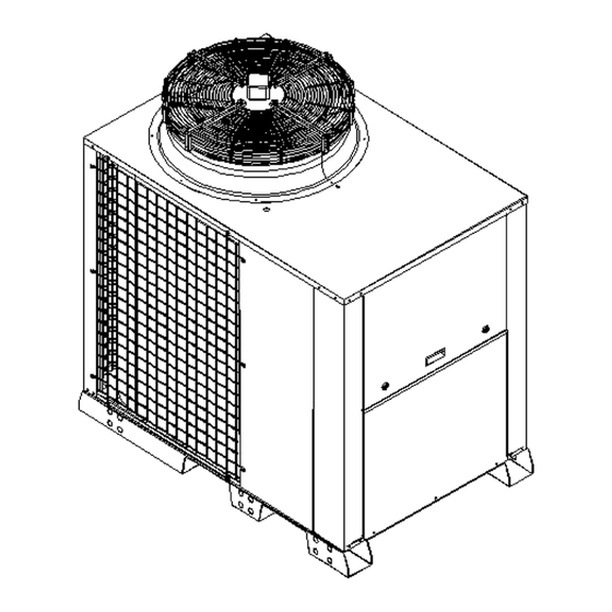
Compressor 1.1.2 Parts of the VITALITY The VITALITY series range is made up of a series of air ‑ air units with centrifugal fans in the indoor unit and axial fans in the outdoor unit. The outdoor unit includes: •... - Page 5 Software installed on the YKN2 Open electronic board provides electronic management for the YKN2 Open control board. In addition, a wide range of accessories is available to adapt the units to the specific requirements of each application. The VITALITY series air conditioning units can be used in extreme weather conditions.
-
Page 6: Description Of The Unit
User manual General description of the unit 1.1.3 Description of the unit Compressors type compressors with internal motor protection and external sump resistor included as standard, which keeps the oil hot for easier start-up and to prevent its drag outside the compressor. They are charged with a POE (polyol-ester) oil to avoid the formation of foam. - Page 7 User manual General description of the unit Electrical panel The electrical panel is directly accessible from the outside by means of a panel with 1/4 turn closures. It includes a connection terminal strip, protectors, electronic boards and sensors, power contactors, switch‐ ing relays, phase control relay and transfer for the 24V control circuit.
-
Page 8: Ykn2 Open Control Circuit
The unit is fitted with connections for specific manometers for easier reading of cooling circuit pressures. 1.2 Intended use of the unit The VITALITY series of units is exclusively designed for the air conditioning of buildings and properties. Therefore, the unit has a cold generating system, a heat pump and, as optional, auxiliary electrical re‐... -
Page 9: Description Of The Unit's Main Control Panel
User manual Description of the unit's main control panel 1.3 Description of the unit's main control panel The main control panel is found on the unit itself and is protected from the outside by a removable metal panel. 1 Connection entry. 2 Grommet support tray. -
Page 10: General Instructions
User manual Operating instructions 1.4.3 General instructions C A U T I O N • Always keep the electrical power supply connected to the unit. • Only disconnect the unit if it is not to be used for a long period of time. •... -
Page 11: Thermostat Connections
User manual Safety and equipment protection systems 1.5.2 Thermostat connections Yellow cable. Red cable. White cable. A. Shielded cable, 2 x 0.5 mm . Maximum length: 100 m. B. Shielded cable, 10 x 0.22 mm . Maximum length: 100 m. 1.6 Safety and equipment protection systems The VITALITY range of air conditioning units includes an entire series of safety and protection systems intended to provide a high degree of safety for users and maintenance personnel. -
Page 12: Placing The Unit Out Of Service For Planned Stoppage Or Malfunction
User manual Placing the unit out of service for planned stoppage or malfunction 1.7 Placing the unit out of service for planned stoppage or mal‐ function 1.7.1 Placing the unit out of service for planned stoppage To stop the air conditioning unit using the DPC-1 ther‐ mostat, press the MODE, -1- key repeatedly until the following appears: OFF, -2-. -
Page 13: Restarting The Air Conditioning Unit In The Case Of Breakdown
User manual Regular maintenance by the user Code Description 13 / 23 / 33 Low pressure switch Indoor fan thermal switch 15 / 25 / 35 Repeated cold start-up or suction temperature < ‑25 °C Gas control 1 or resistor 1 fault Gas control 2 or resistor 2 fault Resistor stage 3 fault Resistor stage 4 fault... -
Page 14: Maintenance Responsibilities Of The User
User manual Regular maintenance by the user 1.8.2 Maintenance responsibilities of the user Like any other machine, the air conditioning unit requires regular maintenance, as the wear to which some of its parts are subjected can effect its mechanical reliability and the safety of those responsible for its maintenance.
Need help?
Do you have a question about the VITALITY series and is the answer not in the manual?
Questions and answers