Table of Contents
Advertisement
Operation Manual
Obtaining Other Language Versions: To obtain information in another language about the use of this product, please contact your local Crown Distributor. If you need
assistance locating your local distributor, please contact Crown at 574-294-8000.
This manual does not include all of the details of design, production, or variations of the equipment; nor does it cover every possible situation which may arise during
installation, operation or maintenance.
The information provided in this manual was deemed accurate as of the publication date; however, updates to this information may have occurred. To obtain the latest
version of this manual, please visit the Crown website at www.crownaudio.com.
Trademark Notice: Crown, Crown Audio, IQ, BCA, and Amcron are registered trademarks of Crown International. HiQnet is a trademark of
Harman International Industries, Inc. Other trademarks are the property of their respective owners.
Some models may be exported under the name Amcron
.
®
©2010 by Crown Audio
, Inc., 1718 W. Mishawaka Rd., Elkhart, Indiana 46517-9439 U.S.A. Telephone: 574-294-8000.
®
142483-1 - 7/10
Advertisement
Table of Contents

Subscribe to Our Youtube Channel
Related Manuals for Crown VRACK


Summary of Contents for Crown VRACK
-
Page 1: Operation Manual
Crown website at www.crownaudio.com. Trademark Notice: Crown, Crown Audio, IQ, BCA, and Amcron are registered trademarks of Crown International. HiQnet is a trademark of Harman International Industries, Inc. Other trademarks are the property of their respective owners. -
Page 2: Important Safety Instructions
Important Safety Instructions 1. Read these instructions. WATCH FOR THESE SYMBOLS: 2. Keep these instructions. The lightning bolt triangle is used to alert the user to the risk of electric shock. 3. Heed all warnings. The exclamation point triangle is used to alert the user to important 4. -
Page 3: Declaration Of Conformity
Yateley, GU46 6YS United Kingdom Equipment Type: Commercial Audio Power Amplifiers Family Name: ITECH-HD Model Names: VRack EMC Standards: EN 55103-1:1997 Electromagnetic Compatibility - Product Family Standard for Audio, Video, Audiovisual and Entertainment Lighting Control Apparatus for Professional Use, Part 1: Emissions EN 55103-1:1997 Magnetic Field Emissions-Annex A @ 10 cm and 20 cm EN 61000-3-2:2005 &... -
Page 4: Table Of Contents
Table of Contents Features ..................................5 Setup ..................................6 VRack Power Distribution Overview ............................9 I-Tech HD Amplifier Specifications ............................12 Input Panel ..................................15 Input Wiring Modes................................16 Analog ..................................16 Digital ..................................21 Hybrid ..................................24 Network Wiring Schematic ..............................26 VDrive ..................................27 Output Panel ..................................28 Output Wiring Modes ................................29 HiQnet™... -
Page 5: Features
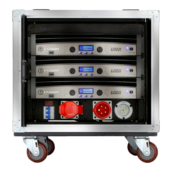
Welcome The VRack is comprised of a rugged touring rack fitted with three Crown IT12000HD amplifiers, a power input panel, and input and output panels. The input panel is mounted at the top rear and supplies CobraNet™ network connections as well as AES/EBU and analog connections. -
Page 6: Setup
Setup Rack Specific Weight: 184 lbs (84.5 kg) Dimensions: L x W x H with caster plate – 22 ½” X 23 ½” X 31 ¼” ( 57.2 cm X 59.7 cm X 79.4 cm ) L x W x H without caster plate – 22 ½” X 23 ½” X 25 7/8” (57.2 cm X 59.7 cm X 65.7 cm) Front View (23-1/2"... - Page 7 Do not suspend the speaker until the proper corrective action has been taken. Use only load-rated hardware when suspending the VRack. Are You New to Suspension? If you are new to suspension, you should do the following: •...
- Page 8 Accessory suspension hardware provided with or for the Crown VRack must be inspected for fatigue at least annually. The inspection shall include a visual material survey for signs of corrosion, bending or any other condition that may decrease strength of the fastener. For other fittings used, refer to the manufacturer’s inspection and maintenance guidelines for process.
-
Page 9: Vrack Power Distribution Overview
220VAC – 240VAC input to 220VAC – 240VAC output. It also features a 32A per circuit, 3-pole, single-throw breaker as well as an LCD readout that indicates AC Voltage. Also, built-in +5V and +12V outputs power the VRack’s built-in network switch and rear rack lighting features. - Page 10 240VAC operation from the Cee-Form pin and sleeve connector. From an external power distribution system, send 3 phase 220VAC-240VAC power to the X, Y, and Z pin of the Cee-Form connector and the VRack will operate in 220VAC-240VAC operation mode. Each I-Tech HD amplifier will see a dedicated line-to-neutral connection as well as a ground.
- Page 11 Setup Power Supply Schematic Operation Manual page 11...
-
Page 12: I-Tech Hd Amplifier Specifications
I-Tech HD Amplifier Specifications The Crown I-Tech HD Series offers amazing power, light weight and ease of use for touring sound applications. Unlike other ® amplifiers, it includes onboard high-definition DSP, an LCD control screen, and a built-in network connection. Modern power amplifiers are sophisticated pieces of engineering capable of producing extremely high power levels. -
Page 13: Front Panel Features
Front Panel Features Three IT12000HD Amplifiers LCD Voltage Readout L21-30 Hubbell Connector 32A Breakers 5-Pin Cee-Form Input 5-Pin Cee-Form Loop Out Back Panel Features Input Panel Output Panel Operation Manual page 13... - Page 14 Setup Choose Input Wire and Connectors Crown recommends using pre-built or professionally wired, balanced line (two-conductor plus shield), 22-24 gauge cables and connectors. Use 3-pin male XLR connectors. Unbalanced line may also be used but may result in noise over long cable runs.
-
Page 15: Input Panel
Network Connection. Function 2 - If no AES3 connection is landed to the rack, this will pull the AES3 signal from a VRack within the network's ring topology that has AES3 landed to its connector and the VDrive switch engaged. See VDrive section for more information. -
Page 16: Input Wiring Modes
Analog Input Wiring Schematic Analog Input Rack Wiring Schematic Operation Manual page 16... -
Page 17: Operation Manual
Input Wiring Modes - Analog Mono 1 MONO 1 MONO 2 STEREO MONO (1+2) 3-MIX MONO 1 + AUX MONO 2 + AUX Mono 2 MONO 1 MONO 2 STEREO MONO (1+2) 3-MIX MONO 1 + AUX MONO 2 + AUX Operation Manual page 17... - Page 18 Input Wiring Modes - Analog Stereo MONO 1 MONO 2 STEREO MONO (1+2) 3-MIX MONO 1 + AUX MONO 2 + AUX Mono (1+2) MONO 1 MONO 2 STEREO MONO (1+2) 3-MIX MONO 1 + AUX MONO 2 + AUX Operation Manual page 18...
- Page 19 Input Wiring Modes - Analog 3-Mix MONO 1 MONO 2 STEREO MONO (1+2) 3-MIX MONO 1 + AUX MONO 2 + AUX Mono 1 + Aux MONO 1 MONO 2 STEREO MONO (1+2) 3-MIX MONO 1 + AUX MONO 2 + AUX Operation Manual page 19...
- Page 20 Input Wiring Modes - Analog Mono 2 + Aux MONO 1 MONO 2 STEREO MONO (1+2) 3-MIX MONO 1 + AUX MONO 2 + AUX Operation Manual page 20...
-
Page 21: Digital
Digital Input Wiring Schematic Digital Input Rack Wiring Schematic Operation Manual page 21... - Page 22 Input Wiring Modes – Digital Mono 1 MONO 1 MONO 2 STEREO MONO (1+2) Mono 2 MONO 1 MONO 2 STEREO MONO (1+2) Operation Manual page 22...
- Page 23 Input Wiring Modes - Digital Stereo MONO 1 MONO 2 STEREO MONO (1+2) Mono (1+2) MONO 1 MONO 2 STEREO MONO (1+2) Operation Manual page 23...
-
Page 24: Hybrid
Input Wiring Modes – Hybrid, Digital and Analog 3-Mix 3-MIX MONO 1 + AUX MONO 2 + AUX Mono 1 + Aux 3-MIX MONO 1 + AUX MONO 2 + AUX Operation Manual page 24... - Page 25 Input Wiring Modes – Hybrid, Digital and Analog Mono 2 + Aux 3-MIX MONO 1 + AUX MONO 2 + AUX Stereo + Aux 3-MIX MONO 1 + AUX MONO 2 + AUX Operation Manual page 25...
-
Page 26: Network Wiring Schematic
Network Wiring Schematic Network Input Rack Wiring Schematic Network Switch info: ProSafe 8-Port Gigabit Smart Switch (GS108T) ® Operation Manual page 26... -
Page 27: Vdrive
VDrive VDrive Wiring Schematic Wire Diagram 10Base-T Signal RJ45 Pin # Wire Color (T568A) 1000Base-T Signal (T568A) 100Base-TX Signal White/Green Transmit + BI_DA+ Green Transmit - BI_DA- White/Orange Receive + BI_DB+ Blue AES 1/2 + BI_DC+ White/Blue AES 1/2 - BI_DC- Orange Receive -... -
Page 28: Output Panel
Output Panel NOTE: All SUB outputs jumpered: 1+ -> 2+ and 1- -> 2- Operation Manual page 28... -
Page 29: Output Wiring Modes
Output Wiring Modes 3-Way + 3-Way Mode 2x 3-WAY + 2x 3-WAY 4x 3-WAY + 2x SUB 4x 3-WAY + 4x 2-WAY 6-12 x SUB 18x HF; 18x MF; 18x LF 6-12 x 2-WAY 8x 2-WAY + 6x SUB 24x PASSIVE (1-way) 16x PASSIVE + 4x SUB 12x PASSIVE + 6x SUB Operation Manual... - Page 30 Output Wiring Modes 3-Way + Sub Mode 2x 3-WAY + 2x 3-WAY 4x 3-WAY + 2x SUB 4x 3-WAY + 4x 2-WAY 6-12 x SUB 18x HF; 18x MF; 18x LF 6-12 x 2-WAY 8x 2-WAY + 6x SUB 24x PASSIVE (1-way) 16x PASSIVE + 4x SUB 12x PASSIVE + 6x SUB Operation Manual...
- Page 31 Output Wiring Modes 3-Way + 2-Way Mode 2x 3-WAY + 2x 3-WAY 4x 3-WAY + 2x SUB 4x 3-WAY + 4x 2-WAY 6-12 x SUB 18x HF; 18x MF; 18x LF 6-12 x 2-WAY 8x 2-WAY + 6x SUB 24x PASSIVE (1-way) 16x PASSIVE + 4x SUB 12x PASSIVE + 6x SUB Operation Manual...
- Page 32 Output Wiring Modes Sub Mode/Passive Mode 2x 3-WAY + 2x 3-WAY 4x 3-WAY + 2x SUB 4x 3-WAY + 4x 2-WAY 6-12 x SUB 18x HF; 18x MF; 18x LF 6-12 x 2-WAY 8x 2-WAY + 6x SUB 24x PASSIVE (1-way) 16x PASSIVE + 4x SUB 12x PASSIVE + 6x SUB Operation Manual...
- Page 33 Output Wiring Modes 2-Way Mode 2x 3-WAY + 2x 3-WAY 4x 3-WAY + 2x SUB 4x 3-WAY + 4x 2-WAY 6-12 x SUB 18x HF; 18x MF; 18x LF 6-12 x 2-WAY 8x 2-WAY + 6x SUB 24x PASSIVE (1-way) 16x PASSIVE + 4x SUB 12x PASSIVE + 6x SUB Operation Manual...
- Page 34 Output Wiring Modes 2-Way + Sub Mode 2x 3-WAY + 2x 3-WAY 4x 3-WAY + 2x SUB 4x 3-WAY + 4x 2-WAY 6-12 x SUB 18x HF; 18x MF; 18x LF 6-12 x 2-WAY 8x 2-WAY + 6x SUB 24x PASSIVE (1-way) 16x PASSIVE + 4x SUB 12x PASSIVE + 6x SUB Operation Manual...
- Page 35 Output Wiring Modes 1-Way Passive Mode 2x 3-WAY + 2x 3-WAY 4x 3-WAY + 2x SUB 4x 3-WAY + 4x 2-WAY 6-12 x SUB 18x HF; 18x MF; 18x LF 6-12 x 2-WAY 8x 2-WAY + 6x SUB 24x PASSIVE (1-way) 16x PASSIVE + 4x SUB 12x PASSIVE + 6x SUB Operation Manual...
- Page 36 Output Wiring Modes 1-Way Passive + Sub Mode 2x 3-WAY + 2x 3-WAY 4x 3-WAY + 2x SUB 4x 3-WAY + 4x 2-WAY 6-12 x SUB 18x HF; 18x MF; 18x LF 6-12 x 2-WAY 8x 2-WAY + 6x SUB 24x PASSIVE (1-way) 16x PASSIVE + 4x SUB 12x PASSIVE + 6x SUB...
- Page 37 Output Wiring Modes 1-Way Passive + Sub Mode 2x 3-WAY + 2x 3-WAY 4x 3-WAY + 2x SUB 4x 3-WAY + 4x 2-WAY 6-12 x SUB 18x HF; 18x MF; 18x LF 6-12 x 2-WAY 8x 2-WAY + 6x SUB 24x PASSIVE (1-way) 16x PASSIVE + 4x SUB 12x PASSIVE + 6x SUB...
-
Page 38: Hiqnet™ Software
HiQnet™ Software Preset Tab Preset Name Indication Recall Preset Signal Generator Amp Info Store Preset Internal Switching Frequency of DSP Enable / Disable Output Switching Enable / Disable Front Panel Lockout Enable / Disable USB Lockout Voltage Monitoring for all 3 Amplifiers Monitoring, Mutes, and Attenuation Input Clip Indication Input RMS Meter... -
Page 39: Hiqnet Software
HiQnet Software Input Tab Select which input mode you would like from the list. After selecting the desired input mode, a visual representation of how to connect the VRack input panel will be shown. Compressor Tab Master Input Compressor Compressor Link... - Page 40 HiQnet™ Software Delay Tab Channel-Specific Input Delay in Feet, Meters, and Seconds Input EQ Tab VRack Input Parametric EQ (affects all amps in the rack) Operation Manual page 40...
- Page 41 Enable / Disable Enable / Disable Device Tab Single click on the device to select amplifier-specific settings not included in the VRack device panel. By selecting one of the amplifiers, the I-Tech HD device panel will appear. Operation Manual page 41...
- Page 42 Designing and Recalling Presets The VRack Preset Tab recalls the same preset numbers on all amplifiers; therefore, it is recommended you save system-specific presets by preset numbers. Below is an example of how to set up a 3-Way + Sub VerTec 4889/4880 preset.
-
Page 43: System Diagrams
System Diagrams VerTec 4889 - 6 Per Side - Economy Mode Operation Manual page 43... - Page 44 System Diagrams VerTec 4889/4880 - 3:2 Ratio - High-Performance Mode Operation Manual page 44...
- Page 45 System Diagrams VerTec 4888 - 4 Per Side - Economy Mode Operation Manual page 45...
- Page 46 System Diagrams VerTec 4888 - 6 Per Side - Economy Mode Operation Manual page 46...
- Page 47 System Diagrams VerTec 4888/4880 - 3:2 Ratio - High-Performance Mode Operation Manual page 47...
- Page 48 System Diagrams VerTec 4887A - 6 Per Side - High-Performance Mode Operation Manual page 48...
- Page 49 System Diagrams VerTec 4887A/4880 - 6 Per Side 4887A, 4 per side 4880 - Nominal-Performance Mode Operation Manual page 49...
- Page 50 Notes Operation Manual page 50...
-
Page 51: Product Registration
PRODUCT REGISTRATION Crown Audio, Inc. 1718 W. Mishawaka Rd. Elkhart, IN 46517-9439 Phone: 574-294-8000 Fax: 574-294-8329 www.crownaudio.com Online registration is also available at http://crownweb.crownintl.com/webregistration. Warranty is only valid within the country in which the product is purchased. When this form is used to register your product, it may be mailed or faxed. -
Page 53: Crown Audio Factory Service Information
Crown Audio Factory Service Information Shipping Address: Crown Audio Factory Service, 1718 W. Mishawaka Rd., Elkhart, IN 46517-9439 PLEASE PRINT CLEARLY SRA #: ______________________ (if sending product to Crown factory service) Model: ______________________ Serial number: __________________________ Purchase date: ____________________ PRODUCT RETURN INFORMATION...
Need help?
Do you have a question about the VRACK and is the answer not in the manual?
Questions and answers