Table of Contents
Advertisement
CE Series
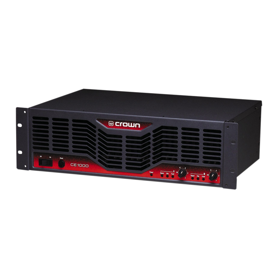
CE 1000
Operation Manual
CE 2000
Obtaining Other Language Versions: To obtain information in another language about the use of this product, please contact your
local Crown Distributor. If you need assistance locating your local distributor, please contact Crown at 574-294-8000.
This manual does not include all of the details of design, production, or variations of the equipment. Nor does it cover every possible
situation which may arise during installation, operation or maintenance.
The information provided in this manual was deemed accurate as of the publication date. However, updates to this information may have
occurred. To obtain the latest version of this manual, please visit the Crown website at www.crownaudio.com.
Trademark Notice: Crown and Amcron are registered trademarks of Crown International. Other trademarks are the property of their
respective owners.
®
Some models may be exported under the name Amcron.
©2003 by Crown Audio Inc., P.O. Box 1000, Elkhart, Indiana 46515-1000 U.S.A. Telephone: 574-294-8000
125645-8
8/03
Advertisement
Table of Contents

Related Manuals for Crown CE Series


Summary of Contents for Crown CE Series
-
Page 1: Operation Manual
Trademark Notice: Crown and Amcron are registered trademarks of Crown International. Other trademarks are the property of their respective owners. ® Some models may be exported under the name Amcron. ©2003 by Crown Audio Inc., P.O. Box 1000, Elkhart, Indiana 46515-1000 U.S.A. Telephone: 574-294-8000 125645-8 8/03... -
Page 2: Important Safety Instructions
TIES SERVICEABLE À L’INTÉRIEUR. TOUS REPA- RATIONS DOIT ETRE FAIRE PAR PERSONNEL QUALIFIÉ SEULMENT. IMPORTANT CE Series amplifiers require Class 2 output wiring. MAGNETIC FIELD CAUTION! Do not locate sensitive high-gain equip- ment such as preamplifiers or tape decks directly above or below the unit. -
Page 3: Declaration Of Conformity
CE Series Power Amplifiers Crown International, Inc. Issued By: Crown International, Inc. 1718 W. Mishawaka Road Elkhart, Indiana 46517 U.S.A. Competent Body’s Name and Address: Technology International (Europe) Limited 41-42 Shrivenham Hundred Business Park, Shrivenham, Swindon, Wilts, SN6 8TZ Equipment Type: Commercial Audio Power Amplifiers... -
Page 4: Table Of Contents
3.4 Back Panel Controls ... 14 4 Advanced Features and Options ... 15 4.1 Protection Systems ... 15 page 4 CE Series Power Amplifiers 4.1.1 Bias Servo ...15 4.1.2 Fault ...15 4.1.3 Ultrasonic and Radio Frequency Protection ...15 4.1.4 Drive Protection...15 4.1.5 Compression ...15... -
Page 5: Welcome
• Selectable input sensitivity. In addition, CE Series amplifiers include a • Proportional-speed fan optimizes cooling number of features which require some expla- efficiency. -
Page 6: Setup
NOTE: When transporting, amplifiers should be supported at both front and back. Figure 2.1 CE 1000 and CE 2000 Dimensions CE Series Power Amplifiers 2.3 Ensure Proper Cooling When using an equipment rack, mount units directly on top of each other. Close any open spaces in rack with blank panels. -
Page 7: Choose Input Wire And Connectors
CE Series Power Amplifiers 2 Setup 2.4 Choose Input Wire and Connectors You have three choices of input connectors: 1/4-inch (6.35-mm) phone, 3-pin XLR, or barrier strip. You can also use either balanced or unbalanced wiring. Figure 2.3 shows balanced connector pin assignments for XLR and phone. -
Page 8: Choose Output Wire And Connectors
(Figure 2.6) at one end and appropriate connectors to fit your speakers at the other end. If your CE Series amplifier came equipped with the CEAS1 (barrier strip) or CEAS2 (5-way bind- ing post) optional output connectors, you may wire your output to these connectors instead. -
Page 9: Wire Your System
CE Series Power Amplifiers 2 Setup 2.6 Wire Your System 2.6.1 Stereo Mode Make sure the amplifier is turned off and the level controls are turned down before you wire the system. Typical input and output wiring is shown in Figure 2.9. -
Page 10: Bridge-Mono Mode
Channel 1 level control works both channels. NOTE: Crown provides a reference of wiring pin assignments for commonly used connector types in the Crown Amplifier Application Guide available at www.crownaudio.com. page 10 Figure 2.11 Typical System Wiring, Bridge-Mono Mode CE Series Power Amplifiers Operation Manual... -
Page 11: Input Sensitivity Switch
CE Series Power Amplifiers 2 Setup 2.7 Input Sensitivity Switch A two-position Input Sensitivity switch is located on the back panel near the input connectors (Figure 2.12). Your amplifier is shipped from the factory with this switch set to the 1.4V position. -
Page 12: Operation
3. Do not short the ground lead of an output cable to the input signal ground. This may form a ground loop and cause oscillations. page 12 CE Series Power Amplifiers 4. WARNING: Never connect the output to a power supply, battery or power main. Electrical shock may result. -
Page 13: Controls, Indicators And Connectors
CE Series Power Amplifiers 3 Operation 3.2 Controls, Indicators and Connectors Figure 3.1 Controls, Indicators & Connectors Operation Manual page 13... -
Page 14: Front Panel Controls And Indicators
If you wish, the level control knobs may be pulled from the front panel and the holes plugged with the supplied caps to minimize tampering of control set- tings. CE Series Power Amplifiers 3.4 Back Panel Controls and Connectors Input Sensitivity Switch This two-position Input Sensitivity switch is located near the input connectors. -
Page 15: Advanced Features And Options
Higher slew rates actually let the amplifier reproduce undesirable frequencies. By design, the CE Series amplifi- ers have a controlled slew rate to put a fre- quency limit on the highest frequencies that they reproduce. - Page 16 SST-4632 Like the SST-3632 but for the JBL 4632 cinema speaker systems. CE Series Power Amplifiers Figure 4.1 SST-SBSC Crossover Network Figure 4.2 SST-4622 Crossover Network Operation Manual...
-
Page 17: Fault Monitoring
4.2.2 Fault Monitoring The Fault (RJ-11) jack, which looks like a telephone jack, is located on the back of your CE Series ampli- fier (Figure 4.3). It gives you an easy way to remotely monitor the amplifier’s fault status. To set... -
Page 18: Options
Center. For more information, please contact Crown Technical Support. page 18 4.3.3 Tamper-Resistant Hole Plugs Your CE Series amplifier comes with a set of tamper-resistant hole plugs, which allow you to “protect” the level controls against unauthorized adjustment. To use, simply pull off the control knobs from the front of the amp, and slip the hole plugs into place (see Figure 4.8). -
Page 19: Principles Of Operation
CE Series Power Amplifiers 5 Principles of Operation For the sake of simplicity, only channel one of the amplifier is described. Signal is presented to the CE amplifier through one of three connectors when using the stan- dard input module. Each channel is outfitted with a balanced XLR/phone jack and a barrier strip. - Page 20 COMPRESSOR CONTROL TRANSLATOR BUFFER ERROR VARIABLE GAIN STAGE –VCC TO SIGNAL PRESENCE INDICATOR DC PROTECT LOGIC FAULT CONNECTOR MUTE CE Series Power Amplifiers HEATSINK TRIPLE-DEEP TEMPERATURE DARLINGTON NPN POSITIVE OUTPUT STAGE TDVI BIAS BIAS BIAS BIAS BIAS BIAS LIMITER TRIPLE-DEEP...
-
Page 21: Troubleshooting
CE Series Power Amplifiers 6 Troubleshooting CONDITION: Fault indicator is flashing. POSSIBLE REASON: • • • • • The fault status of the amplifier can also be moni- tored remotely by attaching a signal device to the Fault jack located on the amplifier back panel. See Section 4.2.2 for more detail. -
Page 22: Specifications
90 watts Proportional speed fan EIA Standard 19 in. (48.3 cm) x 5.25 in. (13.34 cm) x 12.25 in. (31.11 cm) 32.6 lb (14.79 kg), 38.6 lb (17.49 kg) CE Series Power Amplifiers CE 2000 975 W 660 W 400 W... -
Page 23: Service
CE Series Power Amplifiers 8 Service Crown amplifiers are quality units that rarely require servicing. Before returning your unit for servicing, please contact Crown Technical Support to verify the need for servicing. This unit has very sophisticated circuitry which should only be serviced by a fully trained techni- cian. -
Page 24: Warranty
DISCLAIMER OF CONSEQUENTIAL AND INCIDENTAL DAMAGES THIS STATEMENT OF WARRANTY SUPERSEDES ANY OTHERS CONTAINED IN THIS MANUAL YOU ARE NOT ENTITLED TO RECOVER FROM FOR CROWN PRODUCTS. US ANY INCIDENTAL DAMAGES RESULTING CE Series Power Amplifiers 12/01 Operation Manual... - Page 25 CE Series Power Amplifiers 9 Warranty SUMMARY OF WARRANTY Crown International, 1718 West Mishawaka Road, Elkhart, Indiana 46517-4095 U.S.A. warrants to you, the ORIGINAL PURCHASER and ANY SUB- SEQUENT OWNER of each NEW Crown1 product, for a period of three (3) years from the date of pur- chase by the original purchaser (the “warranty...
- Page 26 CE Series Power Amplifiers This page intentionally left blank. page 26 Operation Manual...
-
Page 27: Crown Factory Service Information Form
CE Series Power Amplifiers Owner’s Name : ________________________________________________________________________________________________________________________________________________________________ Shipping Address: ______________________________________________________________________________________________________________________________________________________________ Phone Number: ________________________________Fax Number: ________________________________ Email ________________________________________________________________________________ Model: __________________________________________________________________________________ Serial Number: ________________________________________________________________________ Purchase Date : ________________________________________________________________________________________________________________________________________________________________ (Be sure to describe the conditions that existed when the problem occurred and what attempts were made to correct it.)
Need help?
Do you have a question about the CE Series and is the answer not in the manual?
Questions and answers