Table of Contents
Advertisement
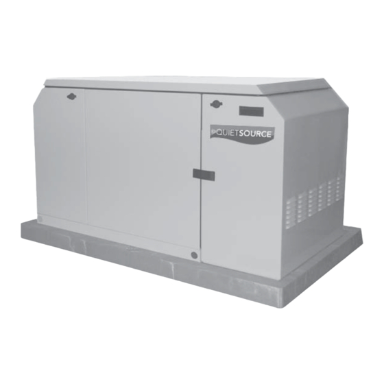
Installation and
Owner's Manual
Air-cooled, Prepackaged
Automatic Standby Generators
Model No. 004916-0
(10 kW NG, 11 kW LP)
*This manual should
remain with the unit.
Not intended for use as Primary Power in place of utility or in
life-support applications.
DANGER
DEADLY EXHAUST FUMES. OUTDOOR INSTALLATION ONLY!
Advertisement
Table of Contents

Subscribe to Our Youtube Channel
Related Manuals for Generac Power Systems Quietsource 004916-0


Summary of Contents for Generac Power Systems Quietsource 004916-0
- Page 1 Installation and Owner’s Manual Air-cooled, Prepackaged Automatic Standby Generators Model No. 004916-0 (10 kW NG, 11 kW LP) *This manual should remain with the unit. Not intended for use as Primary Power in place of utility or in life-support applications.
-
Page 2: Introduction
INTRODUCTION Thank you for purchasing this model of the Quiet Source product line by Generac Power Systems Inc. This model is a compact, high performance, air- cooled, engine-driven generator designed to auto- matically supply electrical power to operate critical loads during a utility power failure. -
Page 3: Table Of Contents
Introduction ... Inside Front Cover Read This Manual Thoroughly ... IFC Contents ... IFC Operation and Maintenance ... IFC How to Obtain Service ... IFC Authorized Dealer Locator Number ... IFC Safety Rules ... 2 Standards Index ... 3 Section 1 – General Information ... 4 Unpacking/Inspection ... -
Page 4: Important Safety Instructions
IMPORTANT SAFETY INSTRUCTIONS Air-cooled 11 kW Generators SAVE THESE INSTRUCTIONS – The manufacturer suggests that these rules for safe operation be copied and posted near the unit’s installation site. Safety should be stressed to all operators and potential operators of this equipment. ... -
Page 5: Electrical Hazards
ELECTRICAL HAZARDS • All generators covered by this manual produce dangerous electrical voltages and can cause fatal electrical shock. Utility power delivers extremely high and dangerous voltages to the transfer switch as does the standby generator when it is in opera- tion. -
Page 6: Section 1 - General Information Air-Cooled 11 Kw Generators
Section 1 — General Information Air-cooled 11 kW Generators DANGER Only qualified electricians or contractors should attempt such installations, which must comply strictly with applicable codes, standards and regulations. UNPACKING/INSPECTION After unpacking, carefully inspect the contents for damage. • This standby generator set has been factory sup- plied with a weather protective enclosure that is intended for outdoor installation only. -
Page 7: 120 Volt Ac Outlet
1.4.2 120 VOLT AC OUTLET The generator is equipped with an external, 15 amp, 120 volt, GFCI convenience outlet located on the front of the unit (Figure 1.2). When the generator is running, in the absence of utility power, this outlet may be used to power items outside the home such as lights or power tools. -
Page 8: Specifications
Section 1 — General Information Air-cooled 11 kW Generators SPECIFICATIONS 1.6.1 GENERATOR Rated Max. Continuous Power Capacity (Watts*) Rated Voltage Rated Max. Continuous Load Current (Amps) 120 Volts** 240 Volts Main Line Circuit Breaker Phase Number of Rotor Poles Rated AC Frequency Power Factor Recommended Air Filter Battery Requirement... -
Page 9: Fuel Requirements And Recommendations
FUEL REQUIREMENTS AND RECOMMENDATIONS With LP gas, use only the vapor withdrawal sys- tem. This type of system uses the vapors formed above the liquid fuel in the storage tank. The engine has been fitted with a fuel carburetion system that meets the specifications of the 1997 California Air Resources Board for tamper-proof dual fuel systems. -
Page 10: Transfer Switch
Section 1 — General Information Air-cooled 11 kW Generators 1.10.2 TRANSFER SWITCH This generator should only be installed with a com- patible transfer switch. A range of transfer switches are offered by the manufacturer. 1.11 BATTERY INSTALLATION If the AUTO/OFF/MANUAL switch is not set to its OFF position, the generator can crank and start as soon as the battery cables are connected. -
Page 11: Section 2 - Post Installation Start-Up And Adjustments
The following procedures are to be observed: • Wear full eye protection and protective clothing; • Where electrolyte contacts the skin, wash it off immediately with water; • Where electrolyte contacts the eyes, flush thoroughly and immediately with water and seek medical attention;... -
Page 12: Generator Tests Under Load
Section 2 — Post Installation Start-up and Adjustments Air-cooled 11 kW Generators DANGER Proceed with caution! Generator power voltage is now supplied to the transfer switch. Contact with live transfer switch parts will result in dan- gerous and possibly fatal electrical shock. 10. -
Page 13: Voltage Regulator Adjustment
With the generator running and loads powered by generator AC output, turn ON the utility power supply to the transfer switch. The following should occur: • After about six seconds, the switch should transfer loads back to the utility power source. •... -
Page 14: Off" Position
Section 3 — Operation Air-cooled 11 kW Generators 3.2.2 “OFF” POSITION This switch position shuts down the engine. This position also prevents automatic operation. 3.2.3 “MANUAL” POSITION Set the switch to Manual to crank and start the engine. Transfer to standby power will not occur unless there is a utility failure. -
Page 15: Setting The Exercise Timer
SETTING THE EXERCISE TIMER This generator is equipped with an exercise timer. Once it is set, the generator will start and exercise once every seven days, on the day of the week and at the time of day the following sequence is completed. During this exercise period, the unit runs for approx- imately 12 minutes and then shuts down. -
Page 16: Low Battery
Section 4 — Maintenance Air-cooled 11 kW Generators 3.6.5 LOW BATTERY The microprocessor will continually monitor the bat- tery voltage and turn on the Low Battery LED if the battery voltage falls below 11.0 volts for one minute. Low battery voltage is a non-latching alarm, which will automatically clear if the battery voltage rises above 11.0 volts. -
Page 17: Oil Change Procedure
Any attempt to crank or start the engine before it has been properly serviced with the recom- mended oil may result in an engine failure. 4.3.2 OIL CHANGE PROCEDURE To change the oil, proceed as follows: 1. Run the engine until it is thoroughly warmed up then shut OFF the engine. -
Page 18: Battery Maintenance
Section 4 — Maintenance Air-cooled 11 kW Generators Figure 4.5 – Setting the Spark Plug Gap BATTERY MAINTENANCE The battery should be inspected per the “Service Schedule,” Section 4.13. The following procedure should be followed for inspection: 1. Inspect the battery posts and cables for tightness and corrosion. -
Page 19: Cooling System
• Loosen the rocker jam nut. Use an 10mm allen wrench to turn the pivot ball stud while checking clearance between the rocker arm and the valve stem with a feeler gauge. Correct clearance is 0.002-0.004 inch (0.05-0.1 mm). NOTE: Hold the rocker arm jam nut in place as the pivot ball stud is turned. -
Page 20: Return To Service
Section 4 — Maintenance Air-cooled 11 kW Generators 7. Remove the spark plug(s) and spray fogging agent into the spark plug(s) threaded openings. Reinstall and tighten the spark plug(s). 8. Remove the battery and store it in a cool, dry room on a wooden board. -
Page 21: Service Schedule
4.13 SERVICE SCHEDULE ATTENTION: It is recommended that all service work be performed by the nearest Authorized Dealer. SYSTEM/COMPONENT X = Action R = Replace as Necessary * = Notify Dealer if Repair is Needed. FUEL Fuel lines and connections* LUBRICATION Oil level Oil filter... -
Page 22: Section 5 - Troubleshooting Air-Cooled 11 Kw Generators
Section 5 — Troubleshooting Air-cooled 11 kW Generators TROUBLESHOOTING GUIDE Problem The engine will not crank. The engine cranks but will not start. The engine starts hard and runs rough. The AUTO/OFF/MANUAL switch is set to OFF , but the engine continues to run. -
Page 23: Section 6 - Installation Diagram
Section 6 — Installation Diagram Air-cooled 11 kW Generators Installation Diagram – Drawing No. 0E7612-A... -
Page 24: Section 7 - Electrical Data Air-Cooled 11 Kw Generators Wiring Diagram - Drawing No. 0E7071-B
Section 7 — Electrical Data Air-cooled 11 kW Generators Wiring Diagram – Drawing No. 0E7071-B GOVERNOR ACTUATOR CONTROL PRINTED CIRCUIT BOARD 1 - ON=50Hz OFF=60Hz 2 - SPARE L.E.D - ALARM INDICATORS VOLTAGE REGULATOR BATTERY CHARGER 224B BA - BRUSH ASSEMBLY BCR - BATTERY CHARGE RELAY C1 - 8 POS. - Page 25 11 22 GRD 1 GRD 2 EXTERNAL GFCI OUTLET LOAD LINE 240V GENERATOR OUTPUT TO TRANSFER SWITCH CONTACTOR CUSTOMER CONNECTION Wiring Diagram – Drawing No. 0E7071-B 11 11 Section 7 — Electrical Data Air-cooled 11 kW Generators CLOSEST TO BEARING ENGINE WIRING STATOR BLACK...
- Page 26 Section 7 — Electrical Data Air-cooled 11 kW Generators Electrical Schematic – Drawing No. 0E7073-B BATTERY CHARGER 224B 225B ELECTRONIC VOLTAGE REGULATOR MANUAL AUTO 12VDC ACCESSORY SOCKET CONTROL PRINTED CIRCUIT BOARD GOVERNOR ACTUATOR 224B 225B 225B 224B...
- Page 27 225B 224B 224A 225A 224A 225A 225A 56VA 224A Section 7 — Electrical Data Air-cooled 11 kW Generators Electrical Schematic – Drawing No. 0E7073-B ENGINE AND ALTERNATOR FIELD NEUTRAL 240VAC GENERATOR 12Vdc OUTPUT TO TRANSFER TRANSFER SWITCH RELAY CONTACTOR COIL DIAGRAM KEY BA - BRUSH ASSEMBLY BCR - BATTERY CHARGE RELAY...
-
Page 28: Section 8 - Exploded Views And Parts Lists Air-Cooled 11 Kw Generators Enclosure - Drawing No. 0E4884-B
Section 8 — Exploded Views and Parts Lists Air-cooled 11 kW Generators Enclosure – Drawing No. 0E4884-B "A" "A"... - Page 29 ITEM PART NO. QTY. DESCRIPTION 0E7325 HHFS, 1/4"-20 X 5/8" GRADE 5 0E6884 SEAL, ALTERNATOR SHAFT 0E4706A SOUND BAFFLE INTAKE SCROLL 0D1131 GUARD,FAN 0E4706 SCROLL, INTAKE 0C2824 SCREW TAP-R #10-32 X 9/16" 039253 SCREW HHC M8-1.25 X 20 0A8250 SCREW HHC 3/8"-24 X 2" G8 0C3032 PLATE, FAN 0C3031...
- Page 30 Section 8 — Exploded Views and Parts Lists Air-cooled 11 kW Generators Control Panel – Drawing No. 0E4879-D 11,13 11,12...
- Page 31 ITEM PART NO. QTY. DESCRIPTION 0E3312 ASSEMBLY, HOME STANDBY CONTROLLER 0A1801 ASSEMBLY, BATTERY CHARGER ENGINE 083049 ASSEMBLY, POTTED REGULATOR 092036 PPHM S/LW #6-32 X 1/4" LONG 0D3062A HEX STAND-OFF #6-32 X 3/4" 075235 SCREW HHC M5-0.8 X 30mm 049226 WASHER LOCK M5 051716 NUT HEX M5-0.8 023484D...
- Page 32 Section 8 — Exploded Views and Parts Lists Air-cooled 11 kW Generators GT-990 Engine – Drawing No. 0F2000...
- Page 33 ITEM PART NO. 0C5730A 0E9843 090388 0C5372 0C3005 0E3372A 0D8067A 0C2981C 071983 0E2950 021533 0E1466 0D4041 0C2977 0C5943 0E4357A 082774 0E3223 0C2978 093873 021374 0C2994 0C2997 0C2995 0C2996 0C3011 0C3009 0C3010 050873A 0E9842 0D9756 0C5732A 0C3006 080318 0C2982 093064 0C2979 086515 0D2274 0D3867...
- Page 34 Section 8 — Exploded Views and Parts Lists Air-cooled 11 kW Generators Engine Accessories – Drawing No. 0F2001-D "A" "C" "E" TO REGULATOR "A" "C" "B" "B" "E" 47 46...
- Page 35 ITEM PART NO. QTY. DESCRIPTION 045756 SCREW HHTT M6-1.0 X 10 YC 0D1131 GUARD, FAN 0F1169G HOUSING, BLOWER V-TWIN RV 0C9763 NUT,GROMMET 1/4 PLUG 0E4386 TUBE, INTAKE 0E5079 HOSE, BREATHER 0C3034 NUT HEX M24-2.0 G8 YEL CHR 0C3033 WASHER,BELLEVILLE 25MM BOLT 051754 SCREW HHC M8-1.25 X 12 G8.8 0A5992...
- Page 36 Section 8 — Exploded Views and Parts Lists Air-cooled 11 kW Generators Alternator & Pulleys – Drawing No. 0E4880...
- Page 37 ITEM PART NO. 0E0196A 022129 022145 022259 0C7758 0C3168 0C2417 0E2424A 0E2425 0E2421 0E1078A 0E3020 040976 056893 023897 0E1078 0C4138 043116 022097 022473 0C1752 0C1753B 075224D 073118 0E5984 022131 0C2824 0A9827B 042633 022237 049451 0C1441 0C1112 083512 039288 029459 075215 052858 075237 075242...
- Page 38 Section 8 — Exploded Views and Parts Lists Air-cooled 11 kW Generators Regulator – Drawing No. 0E4881-C...
- Page 39 ITEM PART NO. 0D5694 0F5022 0C4647 0C4680 0C6070 0F4795 0D3973 0E6183 0E6184 0D3308 0C5761 0C5968 0C6066 0C5759 0C5764 070728 0C6069 0C5762 045764 0C6731 0C6067 0C4706 0C6068 0C4643A 026073 0E1010A 0C5760G 0C6606 Section 8 — Exploded Views and Parts Lists Regulator – Drawing No. 0E4881-C QTY.
-
Page 40: Section 9 - Notes Air-Cooled 11 Kw Generators
Section 9 — Notes Air-cooled 11 kW Generators... - Page 41 Section 9 — Notes Air-cooled 11 kW Generators...
-
Page 42: Section 10 - Warranty Air-Cooled 11 Kw Generators
Warranty (ECS Warranty), which is provided to you by Generac pursuant to California law. See also the “Generac Limited Warranties for Generac Power Systems, Inc.,” which is enclosed herewith on a separate sheet, also provided to you by Generac. The ECS Warranty applies only to the emission control system of your new engine. If there is any conflict in terms between the ECS Warranty and the Generac Warranty, the ECS Warranty shall apply except in circumstances where the Generac Warranty may provide a longer warranty period. -
Page 43: Emission Control System Warranty
Emission Control System Warranty (ECS Warranty) for 1995 and later model year engines: (a) Applicability: This warranty shall apply to 1995 and later model year engines. The ECS Warranty Period shall begin on the date the new engine or equipment is purchased by/delivered to its original, end-use purchaser/owner and shall continue for 24 consecutive months thereafter. -
Page 44: Warranty Schedule
“PREPACKAGED EMERGENCY AUTOMATIC STANDBY GENERATORS” For a period of two years from the date of original sale, Generac Power Systems, Inc. (Generac) warrants that its Quietsource gen- erator will be free from defects in material and workmanship for the items and period set forth below. Generac will, at its option, repair or replace any part which, upon examination, inspection and testing by Generac or an Authorized Warranty Service Dealer, is found to be defective.
Need help?
Do you have a question about the Quietsource 004916-0 and is the answer not in the manual?
Questions and answers