
Related Manuals for Generac Power Systems 00941-4


Summary of Contents for Generac Power Systems 00941-4
-
Page 1: Installation Instructions
Owner’s Manual and Installation Instructions Air-cooled Recreational Vehicle Generator • Model No: 00941-4 IMPACT-36 plus II with Inverter This manual should remain with the unit. -
Page 2: Introduction
INTRODUCTION Thank you for purchasing this generator by Generac Power Systems, Inc. This model is designed and manufactured to supply electrical power for recre- ational vehicles. ◆ READ THIS MANUAL THOROUGHLY If any portion of this manualis not understood, con- tact the nearest Generac Authorized Service Dealer for starting, operating, and servicing procedures. -
Page 3: Table Of Contents
Installation Checklist ...34 Section 4 – Troubleshooting ...35 Troubleshooting Guide ...35 Section 5 – Electrical Data...36 Section 6 – Exploded Views and Parts Lists ...38 Section 7 – Installation Diagram ...47 Section 8 – Warranty...48 Generac ® Power Systems, Inc. -
Page 4: Safety Rules
Ensure all steps are taken to render the machine safe before attempting to work on the generator. GENERAL HAZARDS • For safety reasons, Generac recommends that the installation, initial startup, and maintenance of this equipment be performed by a Generac Authorized Service Dealer. -
Page 5: Fire Hazards
Never work on the equipment when physically or mentally fatigued. • Inspect the generator regularly, and contact the nearest Generac Authorized Service Dealer imme- diately for parts needing repair or replacement. • Before performing any maintenance on the genera- tor, disconnect its battery cables to prevent acci- dental startup. -
Page 6: Section 1 - General Information
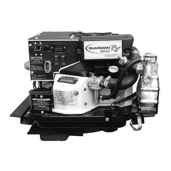
3. Air Intake Tube 4. LP Fuel Regulator 5. Oil Dipstick and Filler Tube 6. LP Carburetor 7. LP Fuel Solenoid 8. Fuel Primer Switch Generac ® Power Systems, Inc. 2. Serial Number __________________ 4. Rated Voltage __________________ 6. Hertz __________________________ REFERENCE NUMBER IDENTIFICATION 9. - Page 7 1.1.2 INVERTER FEATURES (PART NO. 0D4885) 1. Inverter 2. 12 Pin Connection 3. Customer AC Output Section 1 – General Information IMPACT-36 plus II Recreational Vehicle Generator REFERENCE NUMBER IDENTIFICATION 4. DC Input 5. Cooling Fan Generac ® Power Systems, Inc.
-
Page 8: Generator Applicability
Before using the generator set, carefully read GEN- ERAL SAFETY RULES inside the cover. Comply with these RULES to prevent accidents and damage to equipment and/or property. Generac suggests copy- ing and posting the GENERAL SAFETY RULES in potential hazard areas of the recreational vehicle. -
Page 9: Engine Protective Devices
◆ 2.1.3 FUEL SUPPLY The engine must have adequate supply of proper fuel to operate. Before starting, check that sufficient fuel is available. Generac NOTE: ® Power Systems, Inc. -
Page 10: Cooling And Ventilating Air
CLES MAY USE AN ISOLATING RECEPTACLE. SOME VEHICLES MAY BE EQUIPPED WITH A DC CONVERTER WHICH ALLOWS THE GENERATOR TO POWER CERTAIN DC LIGHTING AND OTHER DC LOADS. Generac ® Power Systems, Inc. To crank and start the generator engine, proceed as follows: 1. -
Page 11: Applying Loads To Generator
If the motor home generator has been submerged in water, it must NOT be started or operated. Following any submersion in water, have an authorized Generac Service Facility thoroughly clean and dry the generator. OPERATION IN HIGH GRASS OR BRUSH Never operate the generator while the vehicle is parked in high grass, weeds, brush or leaves. -
Page 12: Section 3 - Maintenance
Figure 3.1 — Oil Dipstick and Fill Tube Oil Dipstick and Fill Tube NOTE: See “Engine Oil Requirements”, Section 2.9 for recommended oils. 10 Generac ® Power Systems, Inc. CHANGE ENGINE OIL Change engine oil after the first 25 hours of opera- tion. -
Page 13: Engine Air Cleaner
Salt, as from sea air, worsens the problem since it tends to absorb moisture from the air. The combination of salt and moisture makes a good elec- trical conductor. Generac ® Power Systems, Inc. 11... -
Page 14: Battery
The carburetor should not be tampered with, as this will void the emission control system warranty. If the generator is used at altitudes in excess of 5,000 feet, consult the Generac Authorized Service Facility regarding high altitude jetting changes. 3.13 ADJUSTING VALVE CLEARANCE After the first 50 hours of operation, adjust the valve clearance in the engine. -
Page 15: Major Service Manual
Be sure to identify the unit’s MODEL NUMBER and SERIAL NUMBER. 3.15 EXERCISING THE GENERATOR Generac recommends that the generator is started and operated at least once every seven days. Let the unit run for at least 30 minutes to “exercise” the engine. -
Page 16: Section 4 - Notes
Section 4 – Notes IMPACT-36 plus II Recreational Vehicle Generator 14 Generac ® Power Systems, Inc. -
Page 17: Part Ii - Installation Instructions
PART II – INSTALLATION INSTRUCTIONS DANGER ONLY QUALIFIED ELECTRICIANS OR CONTRACTORS SHOULD ATTEMPT INSTALLATION!! -
Page 18: Safety Rules
(a) use of common hand tools, (b) use of special Generac tools, and (c) use of any tools and/or equipment from other suppliers. Generac cannot possibly know of, nor advise the... -
Page 19: Electrical Hazards
There must be no possibility of fuel vapors enter- ing the vehicle interior. • It is required to install an approved, flexible, non- conductive fuel line between the generator fuel con- nection point and the rigid fuel lines. Generac Safety Rules ® Power Systems, Inc. 17... -
Page 20: Section 1 - General Information
Boulevard, Rexdale, Ontario, Canada, M9W 1R3. EQUIPMENT DESCRIPTION Instructions and information in this section pertain to Generac Impact air-cooled generators — more specifically, the installation of Impact-34 plus II and IMPACT-36 plus II Recreational Vehicle Generators. These generators are designed specifically for installing in recreational vehicles. -
Page 21: Location And Support
Figure 2.2 — Typical Suspended Mounting • The installer must make certain that selected loca- tion will permit adequate cooling and ventilating air flow to be supplied. Generac System ® Power Systems, Inc. 19... -
Page 22: Generator Restraint
ALTERNATIVE TO GALVANIZED STEEL, DUE TO ALUMINUM'S LOW MELTING POINT. • If the compartment is lined with galvanized steel, it may be constructed of any material. Generac rec- ommends that the compartment be constructed of 1/2-inch thick plywood, with the floor made of a double thickness of plywood for added strength. -
Page 23: Compartment Size
Use approved non-flam- mable insulating materials in high tempera- ture areas. Generac NOTE: DANGER NOTE: DANGER ® Power Systems, Inc. 21... -
Page 24: Sound Insulating Materials
For example, a sheet of lead or visco-elastic material, along with a layer of other acoustical mate- rial, is more effective than when a single material is used. Figure 2.7 – Compartment Floor Cutout (0A6203-A) 22 Generac ® Power Systems, Inc. ◆ 2.2.4 COMPARTMENT FLOOR CUTOUTS Provide openings in the generator compartment for the following items (Figure 2.7):... -
Page 25: Cooling And Ventilating Air
The heated air flow is then deflected out the bottom toward the ground. Figure 2.9 — Air Flow Through Engine- Generac DANGER Generator ® Power Systems, Inc. 23... -
Page 26: Cooling Air Inlet Openings
• Provide a door in the vehicle skirt having an air inlet opening (Figure 2.11). 24 Generac ® Power Systems, Inc. Figure 2.11 — Suspended Mount Inlet Door •... -
Page 27: Compensating For Restrictions
12 feet. If the cables are longer than needed, coil the excess near the inverter unit. If a greater length is needed, contact Generac. DO NOT ATTEMPT TO SHORTEN OR LENGTHEN THE SUPPLIED sensing harnesses. The DC power wires may be cut to the required length. -
Page 28: Some Important Considerations
11 inch- es water column. Do NOT exceed 14 inches water column. Figure 2.16 — Propane Gas Carburetion Diagram 26 Generac ® Power Systems, Inc. • The installer must be sure the primary regulator is rated at sufficient gas flow to operate the generator plus all other gas appliances in the circuit. -
Page 29: Fuel Supply Lines
U.S. Forest Service. Use only mufflers and parts approved by Generac. Any per- son(s) installing an unapproved muffler, or an unap- proved exhaust system part, or modifying an exhaust... -
Page 30: Type Of Exhaust System
• Use enough exhaust system hangers to prevent any part of the system from being dislocated. • Use exhaust system parts recommended by Generac. Using unapproved exhaust mufflers and exhaust system parts is the responsibility of the person(s) installing such unauthorized parts. -
Page 31: Generator Ac Connection System
INTERRUPTERS The National Electric Code (NFPA 70, 551-7) requires installation of ground fault circuit inter- rupters (GFCIs) on all external and some internal electrical receptacles. Contact the dealer for recom- mendations. Generac less than units rated ® Power Systems, Inc. 29... - Page 32 Section 2 – Installation IMPACT-36 plus II Recreational Vehicle Generator Figure 2.20 — Transfer Switch Isolation Method Figure 2.21 — Installation with Isolation Receptacle 30 Generac ® Power Systems, Inc. INVERTER POWER CORD FOR DOCKSIDE POWER INVERTER POWER SUPPLY CORD...
-
Page 33: Battery Installation
Select battery cables based on (a) cable length, and (b) prevailing ambient temperatures. Generally, the longer the cable and the colder the weather, the larg- er the cable size must be as shown in the following chart. Generac ® Power Systems, Inc. 31... -
Page 34: Battery Compartment
The minimum size of openings should be 2 square inches at the top of the compartment. Mount the battery on a strong, rigid supporting structure, where leaks and spills of battery fluid will not cause damage. 32 Generac ® Power Systems, Inc. CABLE SIZE ◆... -
Page 35: Section 3 - Post-Installation Startup Checks
The generator engine is equipped with a high tem- perature switch. The switch has normally-open (N.O.) contacts. When the temperature is too high, switch contacts close, and engine shuts down automatically. IMPORTANT: GENERAC RECOMMENDS THAT THE GENERATOR IS TESTED FOR ADEQUATE COOLING. Generac CHECKS SHIPPING. -
Page 36: Installation Checklist
❑ Fuel tank complies with all applicable codes. ❑ Fuel system is properly installed and checked for leaks. DATE OF INSTALLATION NAME OF INSTALLER SIGNATURE OF INSTALLER 34 Generac ® Power Systems, Inc. ◆ EXHAUST SYSTEM ❑ Exhaust system complies with all applicable codes. -
Page 37: Section 4 - Troubleshooting
Reconnect or close wire. Replace board. Reset to ON or CLOSED. Reset and replace if necessary. Set to GENERATOR position. Take generator to an Authorized Generac facility. Take generator to an Authorized Generac facility. Generac ® Power Systems, Inc. 35... -
Page 38: Section 5 - Electrical Data
Section 5 — Electrical Data IMPACT-36 plus II Recreational Vehicle Generator Wiring Diagram and Schematic – Drawing No. 0D4947-B 36 Generac ® Power Systems, Inc. - Page 39 Section 5 — Electrical Data IMPACT-36 plus II Recreational Vehicle Generator Wiring Diagram and Schematic – Drawing No. 0D4947-B Generac ® Power Systems, Inc. 37...
-
Page 40: Section 6 - Exploded Views And Parts Lists
Section 6 — Exploded Views and Parts Lists IMPACT-36 plus II Recreational Vehicle Generator Control Panel – Drawing No. 0E7560 38 Generac ® Power Systems, Inc. - Page 41 SHAKEPROOF EXT. #10 INVERTER ASSEMBLY M3-0.5 NUT WIRE HARNESS-HEATSINK TO PCBI WIRE HARNESS HARNESS-PCBI TO PANEL (NOT SHOWN FOR CLARITY) HARNESS-HEATSINK TO TERM. BLOCK (NOT SHOWN FOR CLARITY) HARNESS, CONTROL PANEL (NOT SHOWN FOR CLARITY) Generac ® Power Systems, Inc. 39...
- Page 42 Section 6 — Exploded Views and Parts Lists IMPACT-36 plus II Recreational Vehicle Generator Sheet Metal – Drawing No. 0F1091 40 Generac ® Power Systems, Inc.
- Page 43 089047 0A9172 091526 084867 0A9031 050830 047290 0C7649 023484D 0E8245 Generac DESCRIPTION BRACKET, MUFFLER HANGER SCREW HHC M6-1.0 X 16mm W/ LOCK WASHER ASSEMBLY, MUFFLER CLAMP EXHAUST SCREEN, SPARK ARREST HOUSING, LOWER FAN SCREW CRIMPTITE #10-24 X 3/8" DEFLECTOR, AIR OUT...
- Page 44 Section 6 — Exploded Views and Parts Lists IMPACT-36 plus II Recreational Vehicle Generator GN 220 RV Long Block – Drawing No. 0A6202-H 42 Generac ® Power Systems, Inc.
- Page 45 HEADBOLT M8 X 56 MM COVER ROCKER W/OUT BREATHER GASKET, BREATHER SCREW HHTT M6-1.0 X 12 YC GEROTER, OUTER 6/5 ASSY,OIL SUMP 220RV WEAR WSHER,VLV SPRNG SEAL,VALVE STEM 6.0 SPARK PLUG (00940 ONLY) SPARK PLUG (00941 ONLY) WASHER,SPRING Generac ® Power Systems, Inc. 43...
- Page 46 Section 6 — Exploded Views and Parts Lists IMPACT-36 plus II Recreational Vehicle Generator Generator – Drawing No. 0F1134 66 83 44 Generac ® Power Systems, Inc.
- Page 47 039253 082774 092800 088905 083512 059636 0D4408 022145 0912970002 092059 049821 Generac DESCRIPTION PLATE, DIVIDER WASHER, CARBURETOR CLIP, ADJUSTMENT ROD, THROTTLE CONTROL SNAP, RETAINING BOLT, AIR CLEANER COVER COVER, AIR BOX ELEMENT, AIR FILTER PLASTITE SC #8 X 0.37" COVER, BREATHER CANAL...
- Page 48 BARBED ELBOW 90 1/2"NPT X 3/8" HOSE 072683A PLUG 1/8" NPTF PIPE 0D3308 WASHER FLAT 3.2MM ID X 10MM OD 070728 SCREW PFILHM M3-0.5 X 5 46 Generac ® Power Systems, Inc. ITEM PART NO. QTY. DESCRIPTION 0C5764A SPRING, REGULATOR 45N/M 29MM 0C4643A INLET, TWIN REG 11.11 DIA.
-
Page 49: Section 7 - Installation Diagram
Section 7 — Installation Diagram IMPACT-36 plus II Recreational Vehicle Generator Major Features and Dimensions – Drawing No. 0F1119 Generac ® Power Systems, Inc. 47... -
Page 50: Section 8 - Warranty
Owner’s Manual. For warranty purposes, Generac recommends that you retain all receipts covering maintenance on your engine. However, Generac cannot deny warranty solely because of the lack of receipts or for your failure to ensure the completion of all scheduled maintenance. - Page 51 Such use voids this ECS Warranty and shall be sufficient grounds for disallowing an ECS Warranty claim. Generac shall not be held liable hereunder for failures of any warranted parts of a Generac engine caused by the use of such an unapproved, add-on, modified, counterfeit and/or “grey market”...
-
Page 52: Generac Power Systems' Three-Year Limited Warranty For Guardian Recreational Vehicle Generators
NOTE: ALL UNITS MUST BE INSTALLED BY GENERAC POWER SYSTEMS AUTHORIZED SERVICE FACILITIES. For a period of 3 (three) years of operation from the date of original sale, Generac Power Systems, Inc. (Generac) will, at its option, repair or replace any part which, upon examination, inspection and testing by Generac or a Generac Authorized Warranty Service Facility, is found to be defective under normal use and service, in accordance with the warranty schedule set forth below.
Need help?
Do you have a question about the 00941-4 and is the answer not in the manual?
Questions and answers