Table of Contents
Advertisement
Copyright and Warranty Notice
The information in this document is subject to change without notice and does not
represent a commitment on part of the vendor, who assumes no liability or
responsibility for any errors that may appear in this manual.
No warranty or representation, either expressed or implied, is made with respect to
the quality, accuracy or fitness for any particular part of this document. In no event
shall the manufacturer be liable for direct, indirect, special, incidental or
consequential damages arising from any defect or error in this manual or product.
Product names appearing in this manual are for identification purpose only and
trademarks and product names or brand names appearing in this document are the
property of their respective owners.
This document contains materials protected under International Copyright Laws. All
rights reserved. No part of this manual may be reproduced, transmitted or
transcribed without the expressed written permission of the manufacturer and
authors of this manual.
If you do not properly set the motherboard settings, causing the motherboard to
malfunction or fail, we cannot guarantee any responsibility.
Advertisement
Table of Contents

Related Manuals for Abit SL6


Summary of Contents for Abit SL6
- Page 1 Copyright and Warranty Notice The information in this document is subject to change without notice and does not represent a commitment on part of the vendor, who assumes no liability or responsibility for any errors that may appear in this manual. No warranty or representation, either expressed or implied, is made with respect to the quality, accuracy or fitness for any particular part of this document.
-
Page 3: Table Of Contents
SL6 Motherboard User’s Manual Index TABLE OF CONTENTS CHAPTER 1. INTRODUCTION OF SL6 FEATURES 1-1. EATURES OF OTHERBOARD 1-2. PECIFICATIONS 1-3. AYOUT IAGRAM 1-4. YSTEM LOCK IAGRAM CHAPTER 2. INSTALLING THE MOTHERBOARD 2-1. NSTALLING THE OTHERBOARD TO THE HASSIS 2-2. - Page 4 APPENDIX E INSTALLING THE VGA DRIVER FOR THE ® WINDOWS NT 4.0 SERVER / WORKSTATION APPENDIX F INSTALLING THE AUDIO DRIVER FOR THE ® WINDOWS NT 4.0 SERVER / WORKSTATION ® APPENDIX G ATA INSTALLATION FOR THE WINDOWS NT 4.0 SERVER / WORKSTATION APPENDIX H INF INSTALLATION FOR THE WINDOWS 2000...
-
Page 5: Features Of Thism
Slot will support a 4MB display cache AGP In-line Memory Module (AIMM). AIMM is a lower cost alternative to a video card. A Communication / Network Riser Slot (CNR Slot) is found on the SL6. The CNR Slot provides audio, modem connectivity. The specification’s main objective is to reduce the cost of audio and modem functionality. -
Page 6: Specifications
Chapter1 1-2. Specifications 1.CPU ® Supports Intel Pentium III FC-PGA based on 100 & 133 MHz FSB. ® Supports Intel Celeron based on 66 MHz FSB ® Reserves support for future Intel Pentium III processors. 2. Chipset Intel 815 chipset Supports 66/100/133MHz (Front Side Bus) Supports AGP 1X/2X/4X (Sideband) 1.5V/3.3V device Supports Advanced Configuration and Power Management Interface (ACPI) - Page 7 Introduction of SL6 Features 7. Multi I/O Functions 2 Channels of Bus Master IDE Ports supporting Ultra DMA 33/66 and future specification devices PS/2 Keyboard and PS/2 Mouse Connectors 1x Floppy Port (up to 2.88MB) 1x Parallel Port (EPP/ECP) 2x Serial Ports...
-
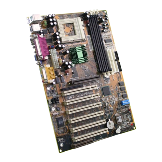
Page 8: Layout Diagram
Chapter1 1-3. Layout Diagram Figure 1-2. SL6 Motherboard component location... -
Page 9: The System Blockd
Introduction of SL6 Features 1-4. The System Block Diagram Figure 1-3. System diagram of the INTEL 815 Chipset User’s Manual... - Page 10 Chapter1...
- Page 11 Chapter 2. Installing the Motherboard This SL6 motherboard not only provides all standard equipment for classic personal computers, but also provides great flexibility for meeting future upgrade demands. This chapter will introduce step by step all of the standard equipment and will also present, as completely as possible, future upgrade capabilities.
-
Page 12: M Otherboard To The C Hassis
Chapter2 2-1. Installing the Motherboard to the Chassis Most computer chassis will have a base on which there will be many mounting holes that allows the motherboard to be securely attached and at the same time, prevents short circuits. There are two ways to attach the motherboard to the base of chassis: ! with studs ! or with spacers Please refer to figure 2-1, which shows the studs and spacers. -
Page 13: P Entium Iii Cpu
Installing the Motherboard Note If the motherboard has mounting holes, but they don’t line up with the holes on the base and there are no slots to attach the spacers, do not despair, you can still attach the spacers to the mounting holes. Just cut the bottom portion of the spacers (the spacers may be a little hard to cut , so mind your fingers). -
Page 14: Installing System Memory
Chapter2 2-3. Installing System Memory This motherboard provides three 168-pin DIMM sites for memory expansion. The DIMM sockets support 8Mx64 (64MB), 16Mx64 (128MB), 32Mx64 and (256MB) DIMM modules. Minimum memory size is 64MB and maximum memory size is 512MB SDRAM. In order to create a memory array, certain rules must be followed. - Page 15 Installing the Motherboard Step 3. Before touching any electronic components, make sure you first touch an unpainted, grounded metal object to discharge any static electricity stored on your clothing or body. Step 4. Locate your computer’s 168-pin memory expansion DIMM socket. Step 5.
-
Page 16: H Eaders And S Witches
Some features you may (or may not) have and need to connect or configure depending on the peripheral. If your system doesn't have such add-on cards or switches you can ignore some special feature connectors. Figure 2-5. All Connectors and Headers for the SL6... - Page 17 Installing the Motherboard First, Let’s look at the headers that the SL6 uses, and what their functions are. (1) ATXPWR1: ATX Power Input Connector Caution If the power supply connectors are not properly attached to the ATXPR1 power supply, the power supply or add-on cards may be damaged.
- Page 18 Chapter2 (3) IR1: IR Header (Infrared) There is a specific orientation for pins 1 through 5, attach the connector from the IR KIT or IR device to the IR1 header (left row only). This motherboard supports standard IR transfer rates. Note: Watch the pin position and the orientation (4) WOL1: Wake on LAN Header...
- Page 19 Installing the Motherboard (5) SMB1: System Management Bus Connector This connector is reserved for system management bus (SM bus). The SM bus is a specific implementation of an I C bus. I C is a multi-master bus, which means that multiple chips can be connected to the same bus and each one can act as a master by initiating a data transfer.
- Page 20 2-10 Chapter2 (8) DIPSW: Front Side Bus Speed Setting DIP Switch This switch allows you to manually setting the front side bus speed. (1) SW1 - SW2 on, SW3 - SW4 off: This is to use the CPU default value (66 / 100 / 133MHz).
- Page 21 Installing the Motherboard 2-11 Note Before you clear the CMOS, you have to first turn the power off (including the +5V standby power). Otherwise, your system may work abnormally or malfunction. (10) PN1 and PN2 Headers PN1 and PN2 are for switches and indicators of the chassis’...
- Page 22 2-12 Chapter2 Note: Watch the HDD LED pin position and the orientation. PN1 (Pin 10 - 11): Power on Switch Header Attach the cable from the case’s front panel power switch to this header. PN1 (Pin 13-14): Hardware Suspend Switch (SMI Switch) Header Attach the cable from the case’s front panel suspend switch (if there is one) to this header.
- Page 23 PIN 13 No connection PIN 14 Suspend signal PIN 14 No connection Let’s now see the I/O connectors that the SL6 uses, and what their functions are. (11) FDC1 Connector This 34-pin connector is called the “floppy disk drive connector”. You can connect a 360K, 5.25”, 1.2M, 5.25”, 720K, 3.5’’,...
-
Page 24: Connectors
2-14 Chapter2 Note A red mark on a wire typically designates the location of pin 1. You need to align pin 1 of the wire to pin 1 of the FDC1 connector and then insert. (12) IDE1 and IDE2 Connectors An IDE hard disk drive ribbon cable has 40 wires and two connectors to provide a connection for two IDE hard disk drives. - Page 25 Installing the Motherboard 2-15 The SL6 supports the Ultra ATA/66 (Also known as Ultra DMA/66) specification. It enhances existing Ultra ATA/33 technology by increasing both performance and data integrity. This new high-speed interface doubles the Ultra ATA/33 burst data transfer rate to 66.6 Mbytes/sec.
- Page 26 Please refer figure 2-10. Figure 2-11. SL6 back panel connectors Figure 2-11 shows the SL6 back panel connectors. These connectors are for connection to outside devices to the motherboard. We will describe which devices will attach to these...
- Page 27 Installing the Motherboard 2-17 KM1 Lower: PS/2 Keyboard Connector Attach a PS/2 keyboard connector to this 6-pin Din-connector. If you use an AT keyboard, you can go to a computer store to purchase an AT to ATX converter adapter. You can then connect your AT keyboard to this connector.
- Page 28 2-18 Chapter2 Serial Port COM1 Connector This motherboard provides one COM port. You can connect an external modem, mouse other devices that support this communication protocol to this connector. You can decide which external device you want to connect to COM1. The COM port can only have one device connected at a time.
- Page 29 Installing the Motherboard 2-19 Line Out, Line In and Mic In Connector Line Out connector: You can connect an external stereo speaker signal input plug to this connector, or you can connect the plug from here to the stereo audio equipment AUX signal input socket.
- Page 30 2-20 Chapter2 MIDI/GAME Port Connector You can connect your joystick, game pad, or other simulation hardware device DIN 15-pin plugs to this connector. Please refer to the further connection notes of the device’s user's manual for further detailed information. Note This chapter contains many color drawing diagram and photos, we strongly recommend you to read this chapter using the PDF file that is included on the CD.
- Page 31 BIOS Setup Chapter 3. Introducing the BIOS The BIOS is a program located on a Flash Memory chip on the motherboard. This program will not be lost when you turn the computer off. This program is also referred to as the boot program.
- Page 32 Chapter3 Figure 3-1. CMOS Setup Utility In the BIOS Setup main menu of Figure 3-1, you can see several options. We will explain these options step by step in the following pages of this chapter, but let us first see a short description of the function keys you may use here: ! Press Esc to quit the BIOS Setup.
- Page 33 BIOS Setup Computer Knowledge: CMOS Data Maybe you have heard somebody saying that his or her CMOS DATA was lost. What is the CMOS? Is it important? The CMOS is the memory used to store the BIOS parameters that you have configured. This memory is passive. You can read its data, and you can also store data in it.
-
Page 34: Cpu Setup
Chapter3 ™ 3-1. CPU Setup [SOFT MENU ™ The CPU can be setup through a programmable switch (CPU SOFT MENU II), that replaces the traditional manual hardware configuration. This feature allows the user to more easily complete the installation procedures. You can install the CPU without configuring any jumpers or switches. - Page 35 BIOS Setup 300 (66) 333 (66) 366 (66) 400 (66) 433 (66) 466(66) 500 (66) 500 (100) 533 (66) 550 (100) 500 (100) 533 (66) 550 (100) 566 (66) 600 (66) 600 (100) 600 (133) 633 (66) 650 (100) 667 (133) 700 (100) 733 (133) 750 (100)
- Page 36 Chapter3 FSB has been set, all of the other components will be able derive their proper operating frequencies. For example: If you have a CPU rated for a 100MHz FSB, the operating frequencies for the proper values for the FSB : SDRAM : PCI for your CPU would be calculated thusly: ®...
- Page 37 BIOS Setup 100MHz (1: 1: 1/3) each multiplied times 3 then (divided by 3) 100MHz (3/3: 3/3: 1/3) each multiplied times 3 then (divided by 3) which both equal: (divided by 3) 100MHz (3:3:1) Now the final point about this table is that it does not show the necessary divider, i.e. for the 100MHz (3:3:1) example you still need to divide each by 3, even though it does not show that in the table.
- Page 38 Giving you all the proper values (within a few MHz or so, its never exactly precise.) ABIT patented technology, SoftMenu™ allows you to adjust the FSB working frequency, when you adjust the working frequency, please choose the proper values for the FSB : SDRAM : PCI for your CPU. For example: ™...
- Page 39 BIOS Setup Note ™ ™ According to Celeron PPGA MMX processor types, some Celeron PPGA MMX processors will have the multiplier factor locked and the signal disabled. In this situation, there is no way to choose a higher multiplier factor. Speed Error Hold: The default setting is “Disabled”.
- Page 40 3-10 Chapter3 CPU and to enter BIOS Setup to set up CPU parameters again. Attention After setting up the parameters and leaving the BIOS SETUP, and having verified that the system can be booted, do not press the Reset button or turn off the power supply. Otherwise the BIOS will not read correctly, the parameters will fail and you must enter ™...
-
Page 41: Standard Cmos Features Setup Menu
BIOS Setup 3-11 3-2. Standard CMOS Features Setup Menu This section contains the basic configuration parameters of the BIOS. These parameters include date, hour, VGA card, FDD and HDD settings. Figure 3-3A. Standard CMOS Setup Screen Shot Date (mm:dd:yy): You can set the date in this item: month (mm), date (dd) and year (yy). Time (hh:mm:ss): You can set the time in this item: hour (hh), minute (mm) and second (ss). - Page 42 3-12 Chapter3 Figure 3-3B. IDE Primary Master Setup Screen Shot IDE HDD Auto-Detection: Press the Enter key for the BIOS to auto detect all detailed parameters of the hard disk drivers (HDD). If auto detection is successful, the correct values will be shown in the remaining items of this menu.
- Page 43 BIOS Setup 3-13 IDE Primary Master: Three settings are available: Auto, Manual and None. If you choose Auto, the BIOS will automatically check what kind of hard disk you are using. If you want to set the HDD parameters yourself, make sure you fully understand the meaning of the parameters, and be sure to refer to the manual provided by the HDD manufacture to get the settings right.
- Page 44 3-14 Chapter3 size given by a disk checking program of a formatted disk. Note All the items below are available when you set the item Primary IDE Master to Manual. Cylinder: When disks are placed directly above one another along the shaft, the circular vertical "slice"...
- Page 45 BIOS Setup 3-15 Floppy 3 Mode Support: Four options are available: Disabled ) Driver A ) Driver B ) Both. The default setting is Disabled. 3 Mode floppy disk drives (FDD) are 3 1/2” drives used in Japanese computer systems. If you need to access data stored in this kind of floppy, you must select this mode, and of course you must have a 3 Mode floppy drive.
-
Page 46: Advanced Bios Features Setup Menu
3-16 Chapter3 3-3. Advanced BIOS Features Setup Menu With each item, you can press <Enter> at any time to display all the options for that item. Attention Advanced BIOS Features Setup Menu has already been set for maximum operation. If you do not really understand each of the options in this menu, we recommend you use the default values. -
Page 47: Virus Warning
BIOS Setup 3-17 Virus Warning: This item can be set to Enabled or Disabled, the default setting being Disabled. When this feature is enabled, if there is any attempt from a software or an application to access the boot sector or the partition table, the BIOS will warn you that a boot virus is attempting to access the hard disk. - Page 48 3-18 Chapter3 First Boot Device: When the computer boots up, the BIOS attempts to load the operating system from the devices in the sequence selected in these items: floppy disk drive A, LS/ZIP devices, hard drive C, SCSI hard disk drive or CD-ROM. There are eleven options for the boot sequence that you can choose (The default setting is Floppy.): Floppy ) LS120 ) HDD-0 ) SCSI ) CDROM ) HDD-1 ) HDD-2 ) HDD-3 ) ZIP100 ) LAN ) Disabled.
- Page 49 BIOS Setup 3-19 Typematic Rate Setting: This item allows you to adjust the keystroke repeat rate. When set to Enabled, you can set the two keyboard typematic controls that follow (Typematic Rate and Typematic Rate Delay). If this item is set to Disabled, the BIOS will use the default setting. The default setting is Enabled.
- Page 50 3-20 Chapter3 Notice Don’t forget your password. If you forget the password, you will have to open the computer case and clear all information in the CMOS before you can start up the system. But by doing this, you will have to reset all previously set options. OS Select For DRAM >...
-
Page 51: Advanced Chipset Features Setup Menu
BIOS Setup 3-21 3-4. Advanced Chipset Features Setup Menu The Chipset Features Setup Menu is used to modify the contents of the buffers in the chipset on the motherboard. Since the parameters of the buffers are closely related to hardware, if the setup is not correct or is false, the motherboard will become unstable or you will not be able to boot up. - Page 52 3-22 Chapter3 The first chipset settings deal with CPU access to DRAM. The default timings have been carefully chosen and should only be altered if data is being lost. Such a scenario might well occur if your system has mixed speed DRAM chips installed. In such a case, greater delays may be required to preserve the integrity of the data held in the slower memory chips.
- Page 53 BIOS Setup 3-23 caching of the video BIOS, resulting in better system performance. However, if any program writes to this memory area, a system error may result. Memory Hole At 15M-16M: Two options are available: Enabled and Disabled. The default setting is Disabled. This option is used to reserve the memory block 15M-16M for ISA adapter ROM.
- Page 54 3-24 Chapter3 Onboard Display Cache Setting: When using the onboard VGA function, you had best use the default setting. CAS# Latency: Two options are available: 2 and 3. The default setting is 3. You can select the local memory clock periods. Paging Mode Control: Two options are available: Close and Open.
-
Page 55: Integrated Peripherals
BIOS Setup 3-25 3-5. Integrated Peripherals In this menu, you can change the onboard I/O device, I/O port address and other hardware settings. Figure 3-6A. Integrated Peripherals Menu Default Screen User’s Manual... - Page 56 3-26 Chapter3 Figure 3-6B. Integrated Peripherals Menu Full Items Screen Onboard IDE-1 Controller: The onboard IDE 1 controller can be set as Enabled or Disabled. The default setting is Enabled. The integrated peripheral controller contains an IDE interface with support for two IDE channels.
- Page 57 BIOS Setup 3-27 third-party IDE bus master driver). Auto: If your hard drive and your system software both support Ultra DMA/33, select Auto to enable BIOS support. For Ultra DMA/66 devices, please refer the requirements mentioned in page 2-18. (Default setting) Disabled: If you encounter a problem in using Ultra DMA devices, you can try to disable this item.
- Page 58 3-28 Chapter3 AC97 Modem: Two options are available: Auto and Disabled. The default setting is Auto. If you set it to Enabled, it will allow the BIOS to detect the modem device you use. If a modem device is ® detected, the onboard modem controller (Intel 815E chipset family) will be able to support it.
- Page 59 BIOS Setup 3-29 The default setting is Ctrl-F1. Onboard FDC Controller: Two options are available: Enabled and Disabled. The default setting is Enabled. You can enable or disable the onboard FDD controller. Onboard Serial Port 1: This is used to specify the I/O address and IRQ of Serial Port 1. Six options are available: Disabled ) 3F8/IRQ4 ) 2F8/IRQ3 ) 3E8/IRQ4 ) 2E8/IRQ3 ) AUTO.
- Page 60 3-30 Chapter3 Rx2Tx2. If you choose RxD2, TxD2, your motherboard must support a COM port IR KIT connection. Otherwise, you can only choose the IR-Rx2Tx2 to use the IR header on your motherboard to connect your IR KIT. Please use the default setting. Onboard Parallel Port: Sets the I/O address and IRQ of the onboard parallel port.
- Page 61 BIOS Setup 3-31 Midi Port IRQ: Two options are available: 5 ) 10. The default setting is 10. This item sets the IRQ of the onboard midi port connector. If you choose disable the Midi Port Address, then this field is not available.
-
Page 62: Power Management Setup Menu
3-32 Chapter3 3-6. Power Management Setup Menu The difference between Green PCs and traditional computers is that Green PCs have a power management feature. With this feature, when the computer is powered on but inactive, the power consumption is reduced in order to save energy. When the computer operates normally, it is in Normal mode. - Page 63 BIOS Setup 3-33 Figure 3-7A. Power Management Setup Main Menu Figure 3-10. Power Management Setup Lower Screen Shot 2. Use the arrow keys to go to the item you want to configure. To change the settings, use ,,- and Enter key. 3.
- Page 64 3-34 Chapter3 There are two options that can be selected, “Enabled” and “Disabled”. You can select “Enabled” to enable ACPI functions. If you want ACPI functions to work normally, you should notice two things. One is your operating system must support ACPI, as of now only ®...
- Page 65 BIOS Setup 3-35 These device/events can wake up the computer…… ……from this state Power switch Sleeping mode or power off mode RTC alarm Sleeping mode or power off mode Sleeping mode or power off mode Modem Sleeping mode or power off mode IR command Sleeping mode Sleeping mode...
-
Page 66: Power Management
3-36 Chapter3 To transition into the S1 state, the operating software does not have to flush the processor's cache. The S3 (STR) State (STR means Suspend to RAM): The S3 state is logically lower then the S2 state and is assumed to conserve more power. The behavior of this state is defined as follows: ! Processor is not executing instructions. - Page 67 BIOS Setup 3-37 User Define “User Define” defines the delay for accessing the power modes. Disabled ) 1 Min ) 2 Min ) 4 Min ) 8 Min ) 12 Min ) 20 Suspend Mode: Min ) 30 Min ) 40 Min ) 1 Hour. The default setting is Disabled.
- Page 68 3-38 Chapter3 Suspend Type: Two options are available: Stop Grant and PwrOn Suspend. The default setting is Stop Grant. Modem Use IRQ: You can specify the IRQ for modem use. Eight options are available: N/A ) 3 ) 4 ) 5 ) 7 ) 9 ) 10 ) 11.
- Page 69 BIOS Setup 3-39 another computer via a network by sending a wake-up frame signal. This feature also allows the PCI card built-in hardware function to support the wake up function without special cables connected to the motherboard. Note This feature needs a specific network interface which is optional. Also your ATX power supply +5V standby power must be at least 720mA compatible.
- Page 70 3-40 Chapter3 IDE Primary Master / IDE Primary Slave: Two options are available: Enabled and Disabled. The default setting is Disabled. If any primary IDE master/slave I/O activity occurs, it will cause the computer to re-count the time elapsed. IDE Secondary Master / IDE Secondary Slave: Two options are available: Enabled and Disabled.
-
Page 71: Pnp/Pci Configurations
BIOS Setup 3-41 3-7. PnP/PCI Configurations This section describes configuring the PCI bus system. PCI, or Personal Computer Interconnect, is a system which allows I/O devices to operate at speeds nearing the speed the CPU itself uses when communicating with its own special components. This section covers some very technical items and it is strongly recommended that only experienced users should make any changes to the default settings. - Page 72 3-42 Chapter3 Computer Knowledge: ESCD (Extended System Configuration Data) The ESCD contains the IRQ, DMA, I/O port, memory information of the system. This is a specification and a feature specific to the Plug & Play BIOS. Resources Controlled By: Two options are available: Auto(ESCD) and Manual. Default setting is Auto(ESCD). When the setting is Auto(ESCD), the IRQ Resources and Memory Resources can not be changed.
- Page 73 BIOS Setup 3-43 For example, if you want to move your hard disk to another computer and don’t want to ® re-install Windows NT, then you can specify the IRQ for the device installed on the new computer to fit the original computer settings. Note If you specify the IRQ in this item, then you cannot specify the same IRQ to the ISA bus, otherwise, it will cause a hardware conflict.
-
Page 74: Pc Health Status
3-44 Chapter3 3-8. PC Health Status You can set the warning temperature for your computer system, and you can check the fan speeds and power supply voltages of your computer system. The features are useful for monitoring all the important parameters within your computer system. We call it the PC Health Status. - Page 75 BIOS Setup 3-45 Note The hardware monitoring features for temperatures, fans and voltages will occupy the I/O address from 294H to 297H. If you have a network adapter, sound card or other add-on cards that might use those I/O addresses, please adjust your add-on card I/O address, to avoid the use of those addresses.
-
Page 76: Load Fail -Safed
3-46 Chapter3 3-9. Load Fail-Safe Defaults Figure 3-14. Load Fail-Safe Defaults Screen Shot When you press <Enter> on this item you get a confirmation dialog box with a message similar to: Load Fail-Safe Defaults (Y/N) ? N Pressing ‘Y’ loads the BIOS default values for the most stable, minimal-performance system operations. -
Page 77: Set Password
BIOS Setup 3-47 When you press <Enter> on this item you get a confirmation dialog box with a message similar to: Load Optimized Defaults (Y/N) ? N Pressing ‘Y’ loads the default values that are factory settings for optimal performance system operations. - Page 78 3-48 Chapter3 message will confirm the password will be disabled. Once the password is disabled, the system will boot and you can enter Setup freely. PASSWORD DISABLED. When a password has been enabled, you will be prompted to enter it every time you try to enter Setup.
-
Page 79: Save & Exit Setup
BIOS Setup 3-49 3-12. Save & Exit Setup Figure 3-18. Save & Exit Setup Screen Shot Pressing <Enter> on this item asks for confirmation: Save to CMOS and EXIT (Y/N)? Y Pressing “Y” stores the selections made in the menus in CMOS - a special section of memory that stays on after you turn your system off. -
Page 80: Exit Without Saving
3-50 Chapter3 3-13. Exit Without Saving Figure 3-19. Exit Without Saving Screen Shot Pressing <Enter> on this item asks for confirmation: Quit without saving (Y/N)? Y This allows you to exit Setup without storing in CMOS any change. The previous selections remain in effect. - Page 81 ® INF Installation Utility for Windows 98 SE Appendix A INF Installation Utility for ® Windows 98 SE ® After you’ve installed Windows 98, you need to install the drivers for your IDE & USB devices. We will tell you step by step in the following section how to do this. Note A-1 You have to install the INF Installation Utility before you install the VGA and audio drivers.
- Page 82 Appendix A Exit the Device manager and insert the SL6 CD-Title into your CD-ROM drive. It should execute the program automatically. If not, you can go to the CD location and execute the execution file from the main directory of this CD-Title. After it is executed, the screen below will appear.
- Page 83 ® INF Installation Utility for Windows 98 SE The License screen will appear. Read it and click "Yes" to go on. This screen will show you the Readme.txt information of this INF installation utility. When you have read it all, click "Next". When installation is complete please choose the item: "Yes, I want to restart my computer now".
- Page 84 Appendix A...
- Page 85 Your system now shows the "Standard Display Adapter [VGA]". Exit the device manager and insert the SL6 CD-Title into your CD-ROM drive, it should execute the program automatically. If not, you can go to the CD location and execute the execution file at the main directory of this CD-Title.
- Page 86 Appendix B Move the cursor to "Intel 815 Graphics Driver" and click on it. Go to the next screen. Move the cursor to "For Windows 95/98" and click on it. Go to the next screen. You will now see the welcome screen and its dialogue box. Click "Next" to go on.
- Page 87 ® Installing the VGA Driver for Windows 98 SE The License screen will appear. Click the "Yes" button to go on. Now you can choose the folder for the destination location you want to install the driver. We suggest you use the default folder as the destination location.
- Page 88 Appendix B When the computer restarts and enters Windows, check System Properties ) Device Manager ) Display Adapters. You should see the device has changed to " Intel [R] 82815 Graphics Controller 4.12.01.2586". After you confirm this change, the update process is now fully complete.
- Page 89 ® Installing the Audio Driver for Windows 98 SE Appendix C Installing the Audio Driver for ® Windows 98 SE ® We will show you how to install the audio drivers for Windows 98 SE operating system. Please enter Control Panel, then check System Properties ) Device Manager ) Other Devices.
- Page 90 Appendix C Select “Search for a better driver than the your device using now. (Recommended)”, and then click “Next.” Select “Specify a Location” and then type “D:\Drivers\YMF752\WIN9X” in the text box. (D is your CD-ROM drive letter) Click “Next.” Click “Next.” Click “Finish.”...
- Page 91 ® Installing the Audio Driver for Windows 98 SE Once Windows has restarted, go to "System Properties" to double check. You should find the "?PCI Multimedia Audio Device" has disappeared, and Yamaha AC-XG audio Codec is there instead. User’s Manual...
- Page 92 Appendix C...
- Page 93 Currently these devices are not Ultra ATA devices. Exit the Device manager and insert the SL6 CD-Title into your CD-ROM drive. It should execute the program automatically. If not, you can go to the CD location and execute the execution file from the main directory of this CD-Title. After it is executed, the screen below will appear.
- Page 94 Appendix D Move the cursor to "Intel Ultra ATA Storage Driver - Install" and click on it. Go to the next screen. The "Welcome" screen and its dialogue box will appear. Click "Next" to go on. The License screen will appear. Read it and click "Yes"...
- Page 95 ® ATA Installation Utility for Windows 98 SE Now you can choose the program folder. Setup will add program icons to those program folders listed. Click "Next" to go When installation is complete please choose the item: "Yes, I want to restart my computer now".
- Page 96 Appendix D...
- Page 97 ® Installing the VGA Drivers for the Windows NT 4.0 Server / Workstation Appendix E Installing the VGA Drivers for the ® Windows NT 4.0 Server / Workstation ® In this section we will show you how to install the VGA drives to your Windows NT 4.0 ®...
- Page 98 Appendix E Leave "Display Properties" and insert the SL6 CD-Title into your CD-ROM drive. It should execute the program automatically. If not, you can go to the CD location and execute the execution file from the main directory of this CD-Title. After it is executed, you will see the screen below.
- Page 99 ® Installing the VGA Drivers for the Windows NT 4.0 Server / Workstation The "Welcome” screen and its dialogue box will appear. Click the "Next" button to go The License screen will appear next. Click the "Yes" button to continue. Now you can choose the folder for the destination location you want.
- Page 100 Appendix E When installation is complete please choose the item: "Yes, I want to restart my computer now". Then click the "Finish" button to restart your computer. Go to check your "Display Properties" again. You will see that the graphics driver is recognized pertinent information is displayed.
- Page 101 ® Installing the Audio Drivers for the Windows NT 4.0 Server / Workstation Appendix F Installing the Audio Drivers for ® the Windows NT 4.0 Server / Workstation ® In this section we will show you how to install the audio drives to your Windows NT 4.0 ®...
- Page 102 NOTE If you want to play a MIDI file in Windows NT, you have to install Soft Synthesizer S- YXG50. You can find this software in the SL6 CD-ROM. You have to specify and manually type the path of driver location. We’ve put the audio drivers under the "DRIVERS\YMF752\...
- Page 103 ® Installing the Audio Drivers for the Windows NT 4.0 Server / Workstation When Windows finds the driver you can choose the item "YAMAHA AC-XG Driver" and click "OK" button. Click “OK.” The screen shows the "System Setting Change" message. You need to restart your computer to complete the updating process.
- Page 104 Appendix F...
- Page 105 You will note that no Intel ATA devices are recognized by the system. Exit the Device Manager and insert the SL6 CD-Title into your CD-ROM drive. It should execute the program automatically. If not, you can go to the CD location and execute the execution file from the main directory of this CD-Title.
- Page 106 Appendix G Move the cursor to “Drivers” and click on it. Move the cursor to “Intel Ultra ATA Storage Driver – Install” and click on it. Go to the next screen. A screen notifying you that the InstallShield Wizard is setting up will appear. Click “Next”...
- Page 107 ® ATA Installation Utility for the Windows NT 4.0 Server / Workstation Now you can choose the folder for the destination location you want to install the driver. We suggest you use the default folder as the destination. When you have decided on the destination, click “Next”.
- Page 108 Appendix G Now, going back to the “Control Panel” and “SCSI ADAPTERS”, you will see that the Intel ATA devices are now recognized.
- Page 109 ® INF Installation Utility for the Windows 2000 Server / Workstation Appendix H INF Installation Utility for the ® Windows 2000 Server / Workstation ® In this section we will show you how to install the ATA Utility to your Windows 2000 ®...
- Page 110 Appendix H Exit the Device Manager and insert the SL6 CD-Title into your CD-ROM drive. It should execute the program automatically. If not, you can go to the CD location and execute the execution file from the main directory of this CD-Title. After it is executed, the screen below will appear.
- Page 111 ® INF Installation Utility for the Windows 2000 Server / Workstation This screen will show you the Readme.txt information of this INF installation utility. When you have read it all, click “Next”. When the installation is complete, please choose the item: “Yes, I want to restart my computer now”.
- Page 112 Appendix H...
- Page 113 ® Installing the VGA Drivers for the Windows 2000 Server / Workstation Appendix I: Installing the VGA Drivers for the ® Windows 2000 Server / Workstation ® In this section we will show you how to install the VGA Drivers to your Windows 2000 ®...
- Page 114 Then choose “Driver”. You will see that the VGA Devices are not recognized. Exit the Device Manager and insert the SL6 CD-Title into your CD-ROM drive. It should execute the program automatically. If not, you can go to the CD location and execute the execution file from the main directory of this CD-Title.
- Page 115 ® Installing the VGA Drivers for the Windows 2000 Server / Workstation The Upgrade Device Driver Wizard screen will appear. Enter “Next” to go on. The Wizard will ask you if you would like the computer to select a suitable driver for you or if you would like to manually select one.
- Page 116 Appendix I Insert the Manufacturers Disk and press “OK” You will be asked which device driver you would like to install. Here, be sure to choose the Intel 82815 Graphics Controller. You will be told that the Wizard is ready to install the driver.
- Page 117 ® Installing the VGA Drivers for the Windows 2000 Server / Workstation Going back to the “Device Manager” and “Display Adapters”, you will see that the VGA Driver has been installed successfully. User’s Manual...
- Page 118 Appendix I...
- Page 119 ® Installing the Audio Drivers for the Windows 2000 Server / Workstation Appendix J: Installing the Audio Drivers for ® the Windows 2000 Server / Workstation ® In this section we will show you how to install the Audio Drivers to your Windows 2000 ®...
- Page 120 Appendix J You will be asked to choose a hardware device. Choose “Add/Troubleshoot a device” and then “Next” to go on. Windows will search for new hardware. Choose “Add a new Device”. Then press “Next” to go on. When asked if you want Windows to search for hardware, choose “No, I want to select the hardware from a list”...
- Page 121 “(Standard system devices)” and “Audio Codecs” and then “Next” to go on. You will be asked to install the driver from disk. Insert the SL6 CD-Title into your CD-ROM drive. Press “Next” to go on. Under Select a Device Driver, the “Yamaha Ac-XG Audio Device”...
- Page 122 Appendix J Press “Next” to begin installation of the Yamaha AC-XG Audio Device. When asked if you wish to continue with installation, press “Next” to go on. You will see that the installation is proceeding without problem.
- Page 123 ® Installing the Audio Drivers for the Windows 2000 Server / Workstation You will be informed that the installation is complete. Press “Finish” When asked if you want to restart your computer in order for the changes to take effect, press “Yes”. Going back to the “Device Manager”...
- Page 124 Appendix J...
- Page 125 Intel ATA devices are recognized by the system. Exit the Device Manager and insert the SL6 CD-Title into your CD-ROM drive. It should execute the program automatically. If not, you can go to the CD location and execute the execution file from the main directory of this CD-Title.
- Page 126 Appendix K Move the cursor to “Drivers” and click on it. Move the cursor to “Intel Ultra ATA Storage Driver – Install” and click on it. Go to the next screen. A screen notifying you that the InstallShield Wizard is setting up will appear. Click “Next”...
- Page 127 ® ATA Installation Utility for the Windows 2000 Server / Workstation Now you can choose the program folder. Setup will add program icons to those program folders listed. Click “Next” to go The system will now start to install the drivers.
- Page 128 Appendix K...
- Page 129 BIOS Flashing User Instructions Appendix L BIOS Flashing User Instructions When your motherboard needs to be upgraded with new features or some compatibility problems in the BIOS need to be fixed, you will need to use this BIOS flash utility. This utility is provided by Award Software makes it easy to flash by yourself.
- Page 130 Appendix L Figure M-2. Award Flash Memory Writer V7.52C Complete Screen Figure M-3 shows you what commands you can use for the flashing program. You need to go into the pure DOS environment and type awdflash. Figure M-3 will then appear. Figure M-3.
- Page 131 .bin names. Please read the BIOS file description before you download it. For example, if you want to update the SL6 BIOS, please follow the procedures described below.
- Page 132 Appendix L Note L-3 Please do not use the Award flash memory writer version earlier than Version 7.52C to flash your SL6 motherboard BIOS. Otherwise, it may cause flash fail or anticipate problems.
- Page 133 Hardware Monitoring Function (Installing the Winbond Hardware Doctor Utility) M-1 Appendix M Hardware Monitoring Function (Installing the Winbond Hardware Doctor Utility) Winbond Hardware Doctor is a self-diagnostic system for PCs and must be used with the Winbond chipset: W83627HF IC series products. It protects PC hardware by monitoring several critical items including power supply voltages, CPU &...
- Page 134 Appendix M Step 3. You can specify the program install path by clicking the “Change Directory” button. Or if you want to use the default path, click the icon to continue the install process. Now the screen will show percentage of installation progress. Step 4.
- Page 135 Hardware Monitoring Function (Installing the Winbond Hardware Doctor Utility) M-3 Step 6. This screen will appear. You will see voltages, fan speeds and temperature readings as well. If any item readings are critical or over their limitations, the reading will turn red. Also, a pop-up window will appear to warn you the system has a problem! The figure below shows the warning message window.
- Page 136 Appendix M Please pay attention to two things when you want to make any changes to the “Configuration” option. Firstly, you have to make sure your new setting is in the proper range. Secondly, after you finished the configuration, you have to save it. Otherwise, the program will start with the default value the next time.
- Page 137 The Installation Guide for Suspend to RAM Appendix N Installation Guide for Suspend to Suspend To RAM (STR) is a cost-effective, optimal implementation of the ACPI 1.0 specification. The ACPI specification defines the S3 sleep state, in which all system context is lost except system memory.
- Page 138 Appendix N After these items show up, you can go to the next step for the STR function setting. 0 How to use the STR function: There are two ways to put your system into STR mode: Method 1: Select “Stand by” in the “Shut Down Windows” area. Step 1: Click “Star”...
- Page 139 The Installation Guide for Suspend to RAM Method 2: Define the case “Power” button to initiate STR sleep Mode Step 1: Open “Control Panel”, and then enter “Power Management”. Step 2: Select “Advanced”, and then set the “Power Buttons” to “Standby”. Step 3: Restart your computer to put these settings into effect.
- Page 140 Appendix N...
- Page 141 Fax this form to your dealer or to the company where you bought the hardware or your nearest ABIT branch office in order to benefit from our technical support. (You can refer to the examples given below) Example 1: With a system including: motherboard (with CPU, DRAM, COAST...) HDD,...
- Page 142 Appendix O line that loads the Sound Card Driver, add a remark REM, in order to disable the Sound Card Driver. See the example below. CONFIG.SYS: DEVICE=C:\DOS\HIMEM.SYS DEVICE=C:\DOS\EMM386.EXE HIGHSCAN DOS=HIGH, UMB FILES=40 BUFFERS=36 REM DEVICEHIGH=C:\PLUGPLAY\DWCFGMG.SYS LASTDRIVE=Z Restart the system. If the system starts and does not reset, you can be sure that the problem is due to the Sound Card Driver.
- Page 143 Troubleshooting (Need Assistance?) 4. DRIVER REV: Note the driver version number indicated on the DEVICE DRIVER disk (if have) as “Release *.**”. For example: User’s Manual...
- Page 144 Appendix O . OS/APPLICATION: Indicate the operating system and applications your are running on the system. ® ® ® Example: MS-DOS 6.22, Windows 95, Windows NT..CPU: Indicate the brand and the speed (MHz) of your CPU. Example:(A) In the “Brand” space, write “Intel”, in the “Specifications” space, write ®...
-
Page 145: Technical Support Form
Troubleshooting (Need Assistance?) % Technical Support Form Company Name: Phone Number: " Contact Person: Fax Number: E-mail Address: Model BIOS ID # Motherboard DRIVER REV Model No. OS/Application Hardware name Brand Specifications IDE1 IDE2 IDE1 IDE2 Drive System Memory (DRAM) ADD-ON CARD Problem Description: User’s Manual... - Page 146 Appendix O...
- Page 147 Also please make sure you have the latest drivers from your peripheral cards makers! 3. Check the ABIT Technical Terms Guide and FAQ on our website. We are trying to expand and make the FAQs more helpful and information rich. Let us know if you have any suggestions.
- Page 148 How they serve you is also a good reference for your next purchase. 6. Contacting ABIT. If you feel that you need to contact ABIT directly you can send email to the ABIT technical support department. First, please contact the support team for the branch office closest to you.
- Page 149 Stevenage, Herts SG1 2UG, UK abituksales@compuserve.com abituktech@compuserve.com Tel: 44-1438-741 999 Fax: 44-1438-742 899 In Germany and Benelux (Belgium, Netherlands, Luxembourg) countries: AMOR Computer B.V. (ABIT's European Office) Van Coehoornstraat 5a, 5916 PH Venlo, The Netherlands sales@abit.nl technical@abit.nl Tel: 31-77-3204428 Fax: 31-77-3204420...
- Page 150 Please contact the reseller from whom you bought the product. You should be able to get RMA service there. 8. Reporting Compatibility Problems to ABIT. Because of tremendous number of email messages we receive every day, we are forced to give greater weight to certain types of messages than to others.
Need help?
Do you have a question about the SL6 and is the answer not in the manual?
Questions and answers