
Related Manuals for Abit NF8 Series


Summary of Contents for Abit NF8 Series
- Page 1 NF8 Series (NF8 Pro/NF8/NF8-V Pro/NF8-V) Socket 754 System Board User’s Manual 4200-0432-04 Rev. 1.01...
- Page 2 No part of this manual may be reproduced, transmitted or transcribed without the expressed written permission of the manufacturer and authors of this manual. If you do not properly set the motherboard settings, causing the motherboard to malfunction or fail, we cannot guarantee any responsibility. NF8 Series...
-
Page 3: Table Of Contents
Table of Contents Chapter 1. Introduction ................1-1 1-1. Features & Specifications ................1-1 1-2. Layout Diagram (NF8 Pro, NF8, NF8-V Pro, NF8-V)......1-3 Chapter 2. Hardware Setup..............2-1 2-1. Install The Motherboard................2-1 2-2. Install CPU and Heatsink.................2-2 2-3. Install System Memory ................2-3 2-4. - Page 4 Appendix C. Install USB 2.0 Driver ..............C-1 Appendix D. Install AMD64 Processor Driver.............D-1 Appendix E. ABIT EQ (The Hardware Doctor Utility) ........E-1 Appendix F. FlashMenu (BIOS Update Utility) ..........F-1 Appendix G. NF8 NVRaid Floppy Disk ...............G-1 Appendix H.
-
Page 5: Chapter 1. Introduction
• Supports NV RAID 3. Memory • Two 184-pin DIMM sockets • Supports DDR400/333/266 non-ECC un-buffered memory • Supports maximum memory capacity up to 2GB 4. ABIT Engineered • ™ ABIT SoftMenu Technology • ™ ABIT CPU ThermalGuard Technology 5. SATA NV RAID •... - Page 6 • ATX form factor: 305 x 245 mm 12. Order Information Model Features NF8 Pro IEEE 1394, S/P DIF In/Out IEEE1394 NF8-V Pro S/P DIF In/Out NF8-V Specifications and information contained herein are subject to change without notice. NF8 Series...
-
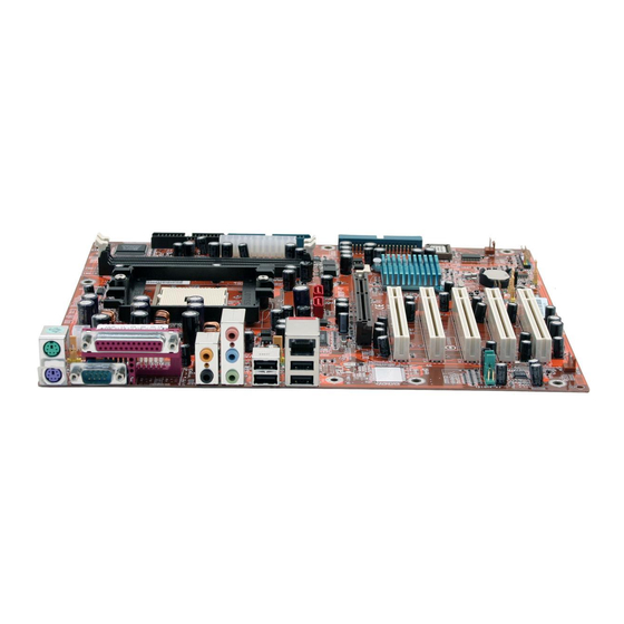
Page 7: Layout Diagram (Nf8 Pro, Nf8, Nf8-V Pro, Nf8-V)
Introduction 1-2. Layout Diagram (NF8 Pro, NF8, NF8-V Pro, NF8-V) User’s Manual... - Page 8 Chapter 1 Chapter 1 NF8 Series NF8 Series...
-
Page 9: Chapter 2. Hardware Setup
Hardware Setup Chapter 2. Hardware Setup Before the Installation: Turn off the power supply switch (fully turn off the +5V standby power), or disconnect the power cord before installing or unplugging any connectors or add-on cards. Failing to do so may cause the motherboard components or add-on cards to malfunction or damaged. 2-1. -
Page 10: Install Cpu And Heatsink
Spring Clip is fully installed. 7. Attach the fan connector of Heatsink & Fan Assembly with the CPU-FAN connector on the motherboard. ATTENTION: Do not forget to set the correct bus frequency and multiple for your processor. NF8 Series... -
Page 11: Install System Memory
Hardware Setup 2-3. Install System Memory This system board provides two 184-pin DDR DIMM slots for DDR 400 memory modules with memory expansion size up to 2GB. Bank Memory Module Total Memory Bank 0, 1 (DIMM1) 256MB, 512MB, 1GB 256MB ~ 1GB Bank 2, 3 (DIMM2) 256MB, 512MB, 1GB 256MB ~ 1GB... -
Page 12: Connectors, Headers And Switches
This motherboard provides two power connectors to connect ATX12V power supplier. NOTE: This 24-pin power connector “ATXPWR1” is compliant to the former 20-pin type. Pay attention to the orientation when doing so (Pin-11, 12, 23, and 24 should be left un-connected). NF8 Series... -
Page 13: Fan Power Connectors
Hardware Setup (2). FAN Power Connectors These connectors each provide power to the cooling fans installed in your system. • CPUFAN1: CPU Fan Power Connector • SYSFAN1: System Fan Power Connector • AUXFAN1, AUXFAN2, PWRFAN1: Auxiliary Fan Power Connector WARNING: These fan connectors are not jumpers. DO NOT place jumper caps on these connectors. User’s Manual... -
Page 14: Cmos Memory Clearing Header
Pin 1-2 shorted (default): Normal operation. • Pin 2-3 shorted: Clear CMOS memory. WARNING: Turn the power off first (including the +5V standby power) before clearing the CMOS memory. Failing to do so may cause your system to work abnormally or malfunction. NF8 Series... -
Page 15: Front Panel Switches & Indicators Headers
Hardware Setup (4). Front Panel Switches & Indicators Headers This header is used for connecting switches and LED indicators on the chassis front panel. Watch the power LED pin position and orientation. The mark “+” align to the pin in the figure below stands for positive polarity for the LED connection. -
Page 16: Additional Usb Port Headers
Ground Ground (6). Additional IEEE1394 Port Headers (NF8 Pro, NF8) This header provides one additional IEEE1394 port connection through an extension cable and bracket. Pin Assignment Pin Assignment TPA0 + TPA0 - TPB0 + TPB0 - +12V +12V NF8 Series... -
Page 17: Wake-Up Header
Hardware Setup (7). Wake-up Header These headers use a jumper cap to enable/disable the wake-up function. • KB-PWR1: Pin 1-2 shorted (default): Disable wake-up function support at Keyboard/Mouse port. Pin 2-3 shorted: Enable wake-up function support at Keyboard/Mouse port. • USBPWR1: Pin 1-2 shorted: Disable wake-up function support at USB1 port. -
Page 18: Front Panel Audio Connection Header
To use the audio connector at rear panel, disconnect the extension cable, attach the jumpers back at pin 5-6, and pin 9-10 (default setting). Pin Assignment Pin Assignment Audio Mic. Ground Audio Mic. Bias Speaker Out Right Speaker Out Right Channel Channel Return Speaker Out Left Speaker Out Left Channel Channel Return NF8 Series... -
Page 19: Internal Audio Connectors
Hardware Setup 2-11 (9). Internal Audio Connectors This connector connects to the audio output of internal CD-ROM drive or add-on card. (10). Accelerated Graphics Port Slot This slot supports an optional AGP graphics card up to AGP 8X mode. ATTENTION: This motherboard does not support 3.3V AGP cards. Use only 1.5V or 0.8V AGP cards. User’s Manual... -
Page 20: Floppy And Ide Disk Drive Connectors
NOTE: Make sure to configure the “Master” and “Slave” relation before connecting two drives by one single ribbon cable. The red line on the ribbon cable must be aligned with pin-1 on both the IDE port and the hard-drive connector. NF8 Series... -
Page 21: Serial Ata Connectors
Hardware Setup 2-13 (12). Serial ATA Connectors These connectors are provided to attach one Serial ATA device at each channel via Serial ATA cable. (13). Status Indicators • LED1 (5VSB): This LED lights up when the power supply is connected with power source. •... -
Page 22: Back Panel Connectors
5.1-channel or regular 2-channel audio system. • IEEE1394: Connects to devices of IEEE1394 protocol. (NF8 Pro, NF8) • LAN: Connects to Local Area Network. • USB1/USB2: Connects to USB devices such as scanner, digital speakers, monitor, mouse, keyboard, hub, digital camera, joystick etc. NF8 Series... -
Page 23: Chapter 3. Bios Setup
BIOS Setup Chapter 3. BIOS Setup This motherboard provides a programmable EEPROM that you can update the BIOS utility. The BIOS (Basic Input/Output System) is a program that deals with the basic level of communication between processor and peripherals. Use the BIOS Setup program only when installing motherboard, reconfiguring system, or prompted to “Run Setup”. -
Page 24: Softmenu Setup
Chapter 3 3-1. SoftMenu Setup The SoftMenu utility is ABIT’s exclusive and ultimate solution in programming the CPU operating speed. All the parameters regarding CPU FSB speed, multiplier factor, the AGP & PCI clock, and even the CPU core voltage are all available at your fingertips. - Page 25 BIOS Setup AGP Clock(MHz): This item allows you to set the AGP clock speed from 66MHz to 100MHz. Due to the AGP specification limit, the speed you set over its standard clock speed is supported, but not guaranteed. Voltage Control: This option allows you to switch between the default and user-defined voltages.
-
Page 26: Standard Cmos Features
2 Master, IDE Channel 3 Master: Click <Enter> key to enter its submenu: IDE HDD Auto-Detection: This item allows you to detect the parameters of IDE drives by pressing <Enter> key. The parameters will be shown on the screen automatically. NF8 Series... - Page 27 BIOS Setup IDE Channel 0 Master/Slave, IDE Channel 1 Master/Slave, IDE Channel 2 Master, IDE Channel 3 Master: When set to [Auto], the BIOS will automatically check what kind of IDE drive you are using. If you want to define your own drive by yourself, set it to [Manual] and make sure you fully understand the meaning of the parameters.
- Page 28 640K for system with 640K or more memory size installed on the motherboard. Extended Memory: This item displays the amount of extended memory detected during system boot-up. Total Memory: This item displays the total memory available in the system. NF8 Series...
-
Page 29: Advanced Bios Features
BIOS Setup 3-3. Advanced BIOS Features Quick Power On Self Test: When set to [Enabled], this item speeds up the Power On Self Test (POST) after powering on the system. The BIOS shorten or skip some check during the POST. Hard Disk Boot Priority: This item selects the hard disks booting priority. - Page 30 This item allows the BIOS to support some old or special IDE devices by prolonging this delay time. A larger value will give more delay time to the device for which to initialize and to prepare for activation. NF8 Series...
-
Page 31: Advanced Chipset Features
BIOS Setup 3-4. Advanced Chipset Features LDT Downstream Width: This item selects the LDT Bus Width. HT Frequency: This item selects the LDT Bus Frequency. DRAM Configuration: Click <Enter> key to enter its submenu: Max Memclock (Mhz): This item selects the maximum memory clock limit. 1T/2T Memory Timing: Leave this item to its default [Auto] setting. - Page 32 [PCI Slot]: When the system boots, it will first initialize PCI. [AGP]: When the system boots, it will first initialize AGP. System BIOS Cacheable: Two options are available: Disabled or Enabled. When you select Enabled, you get faster system BIOS executing speed via the L2 cache. NF8 Series...
-
Page 33: Integrated Peripherals
BIOS Setup 3-11 3-5. Integrated Peripherals OnChip IDE Device: Click <Enter> key to enter its submenu: IDE Function Setup: Click <Enter> key to enter its submenu: User’s Manual... -
Page 34: Raid Config
This option enables or disables the USB controller. If you choose to disable this item, the “USB 2.0 Controller” “USB Keyboard Support Via” “USB Mouse Support Via” and “USB Mass Storage Support” items will not be able to select in Integrated Peripherals menu. NF8 Series... - Page 35 BIOS Setup 3-13 USB 2.0 Controller: This option enables or disables the USB 2.0 controller. USB Keyboard Support Via: This item allows you to select [BIOS] for using USB keyboard in DOS environment, or [OS] in OS environment. USB Mouse Support Via: This item allows you to select [BIOS] for using USB mouse in DOS environment, or [OS] in OS environment.
-
Page 36: Power Management Setup
This item controls the CPU speed by cutting down its regular power to a percentage during the STR (Suspend To RAM) state. Cool ’n’ Quiet Control: This option enables or disables the AMD K8 cool and quiet function. NF8 Series... - Page 37 BIOS Setup 3-15 Power On Function: This item selects the way you want your system to power on. [Password]: Use a password to power on the system, select this option then press <Enter>. Enter your password. You can enter up to 5 characters. Type in exactly the same password to confirm, and then press <Enter>.
- Page 38 3-16 Chapter 3 Day of Month Alarm/ Time (hh:mm:ss) Alarm: You can set the Date (month) Alarm and Time Alarm (hh:mm:ss). Any event occurring will awaken a system that has powered down. NF8 Series...
-
Page 39: Pnp/Pci Configurations
BIOS Setup 3-17 3-7. PnP/PCI Configurations Resources Controlled By: This item configures all of the boot and Plug-and-Play compatible devices. [Auto]: The system will automatically detect the settings. [Manual]: Choose the specific IRQ resources in the “IRQ Resources” menu. IRQ Resources: Click <Enter>... -
Page 40: Pc Health Status
NOTE: The hardware monitoring features for temperatures, fans and voltages will occupy the I/O address from 294H to 297H. If you have a network adapter, sound card or other add-on cards that might use those I/O addresses, please adjust your add-on card I/O address to avoid using these addresses. NF8 Series... -
Page 41: Load Fail-Safe Defaults
BIOS Setup 3-19 3-9. Load Fail-Safe Defaults This option loads the BIOS default values for the most stable, minimal-performance system operations. 3-10. Load Optimized Defaults This option loads the BIOS default values that are factory settings for optimal-performance system operations. 3-11. - Page 42 3-20 Chapter 3 NF8 Series...
-
Page 43: Appendix A. Install Nvidia Nforce Chipset Driver
Install NVIDIA nForce Chipset Driver Appendix A. Install NVIDIA nForce Chipset Driver NOTE: Please install this NVIDIA nForce Chipset driver first after having installed the Windows operating system. The installation procedures and screen shots in this section are based on the Windows XP operating system. - Page 44 Appendix A 10. Click [Yes]. 6. Click [Next]. 11. Choose [Yes, I want to restart my computer now.], and click [Finish] to complete setup. 7. Click [Next]. 8. Click [Next]. 9. Click [Yes]. NF8 Series...
-
Page 45: Appendix B. Install Realtek Audio Driver
Install Realtek Audio Driver Appendix B. Install Realtek Audio Driver The installation procedures and screen shots in this section are based on Windows XP operating system. For those of other OS, please follow its on-screen instruction. Insert the Driver & Utility CD into CD-ROM drive, it should execute the installation program automatically. - Page 46 Appendix B Appendix B NF8 Series NF8 Series...
-
Page 47: Appendix C. Install Usb 2.0 Driver
Install USB 2.0 Driver Appendix C. Install USB 2.0 Driver NOTE: The installation for USB 2.0 driver for Windows XP or Windows 2000 is currently available by updating the latest Service Pack from Microsoft’s web site. User’s Manual... - Page 48 Appendix C Appendix C NF8 Series NF8 Series...
-
Page 49: Appendix D. Install Amd64 Processor Driver
Install AMD64 Processor Driver Appendix D. Install AMD64 Processor Driver The installation procedures and screen shots in this section are based on Windows XP operating system. For those of other OS, please follow its on-screen instruction. Insert the Driver & Utility CD into CD-ROM drive, it should execute the installation program automatically. - Page 50 “Power Options” when the Cool ‘n’ Quiet software for Windows 2000 and ME is installed. This must be set to “Automatic Mode” for Cool 7. Click [Finish]. ‘n’ Quiet to be enabled. 8. Click [Yes] to restart your system. NF8 Series...
-
Page 51: Appendix E. Abit Eq (The Hardware Doctor Utility
ABIT EQ (The Hardware Doctor Utility) Appendix E. ABIT EQ (The Hardware Doctor Utility) ABIT EQ is a self-diagnostic system for PC based on motherboards designed and manufactured by ABIT Computer Corporation. It will protect PC Hardware by monitoring critical items of Power Supply Voltage, CPU &... - Page 52 Appendix E 4. Choose [Yes, I want to restart my computer now.] and click [Finish] to complete setup. 6. This screen appears. ABIT EQ shows you the status of Voltage, Fan Speed, and Temperature readings as well. 5. Execute the ABIT EQ by entering the Windows Menu [Start] $ [All Programs] $ [ABIT] $ [ABIT EQ].
-
Page 53: Appendix F. Flashmenu (Bios Update Utility
ABIT FlashMenu is the most stable Windows-based BIOS flash available. No more worries from crashing. With one click of BIOS updating, ABIT users can flash their BIOS more easily and in less time. The installation procedures and screen shots in this section are based on the Windows XP operating system. - Page 54 Appendix F 5. Execute the FlashMenu by entering the Windows Menu [Start] $ [All Programs] $ [ABIT] $ [FlashMenu]. 6. This FlashMenu screen appears. You can easily update the BIOS from clicking [Update From File], [One Click LiveUpdate], or [LiveUpdate Step by Step] button.
-
Page 55: Appendix G. Nf8 Nvraid Floppy Disk
CD to enter the installation menu. After entering the installation menu, move your curser to [ABIT Utility] tab. Click [NF8 NVRaid Floppy Disk]. The following screen appears. 1. Insert one blank floppy disk to the selected floppy drive and click [Build]. - Page 56 Appendix G Appendix G NF8 Series NF8 Series...
-
Page 57: Appendix H. Troubleshooting (Need Assistance
Troubleshooting (Need Assistance?) Appendix H. Troubleshooting (Need Assistance?) Q & A: Q: Do I need to clear the CMOS before I use a new motherboard to assemble my new computer system? A: Yes, we highly recommend that you clear the CMOS before installing a new motherboard. Please move the CMOS jumper from its default 1-2 position to 2-3 for a few seconds, and then back. - Page 58 Write down the sound card model, motherboard model, BIOS identification number on the technical support file (refer to main instructions), and describe the problem in the space provided. We will show you how to fill the “Technical Support Form”. NF8 Series...
- Page 59 Troubleshooting (Need Assistance?) Main instructions: To fill in this “Technical Support Form”, refer to the step-by-step instructions given below: . MODEL: Note the model number given in your user’s manual. Example: NF8 Pro/NF8/NF8-V Pro/NF8-V . Motherboard model number (REV): Note the motherboard model number labeled on the motherboard as “REV:*.**”.
-
Page 60: Technical Support Form
) Phone Number: ! Company Name: " Contact Person: # Fax Number: * E-mail Address: Model BIOS ID # Motherboard Model No. DRIVER REV OS/Application Hardware Name Brand Specifications IDE1 IDE2 IDE1 CD-ROM-Drive IDE2 System Memory ADD-ON CARD Problem Description: NF8 Series... -
Page 61: Appendix I. How To Get Technical Support
Also please make sure you have the latest drivers from your peripheral cards makers! 3. Check the ABIT Technical Terms Guide and FAQ on our Website. We are trying to expand and make the FAQs more helpful and information rich. Let us know if you have any suggestions. - Page 62 They should have reasonable return or refund policies. How they serve you is also a good reference for your next purchase. 6. Contacting ABIT. If you feel that you need to contact ABIT directly you can send email to the ABIT technical support department. First, please contact the support team for the branch office closest to you.
- Page 63 Unit 3, 24-26 Boulton Road, Stevenage, Herts SG1 4QX, UK Tel: 44-1438-228888 Fax: 44-1438-226333 E-mail: sales@abitcomputer.co.uk Germany and Benelux (Belgium, AMOR Computer B.V. (ABIT's European Office) Netherlands, Luxembourg), Jan van Riebeeckweg 15, 5928LG, Venlo, France, Italy, Spain, Portugal, The Netherlands Greece, Denmark, Norway, Tel: 31-77-3204428...
- Page 64 Please contact the reseller from whom you bought the product. You should be able to get RMA service there. 8. Reporting Compatibility Problems to ABIT. Because of tremendous number of email messages we receive every day, we are forced to give greater weight to certain types of messages than to others.
Need help?
Do you have a question about the NF8 Series and is the answer not in the manual?
Questions and answers