Table of Contents
Advertisement
Quick Links
Copyright and Warranty Notice
The information in this document is subject to change without notice and does not
represent a commitment on part of the vendor, who assumes no liability or responsibility
for any errors that may appear in this manual.
No warranty or representation, either expressed or implied, is made with respect to the
quality, accuracy or fitness for any particular part of this document. In no event shall the
manufacturer be liable for direct, indirect, special, incidental or consequential damages
arising from any defect or error in this manual or product.
Product names appearing in this manual are for identification purpose only and
trademarks and product names or brand names appearing in this document are the
property of their respective owners.
This document contains materials protected under International Copyright Laws. All
rights reserved. No part of this manual may be reproduced, transmitted or transcribed
without the expressed written permission of the manufacturer and authors of this manual.
If you do not properly set the motherboard settings, causing the motherboard to
malfunction or fail, we cannot guarantee any responsibility.
Advertisement
Table of Contents

Related Manuals for Abit AB-NV7-133R


Summary of Contents for Abit AB-NV7-133R
- Page 1 Copyright and Warranty Notice The information in this document is subject to change without notice and does not represent a commitment on part of the vendor, who assumes no liability or responsibility for any errors that may appear in this manual. No warranty or representation, either expressed or implied, is made with respect to the quality, accuracy or fitness for any particular part of this document.
-
Page 3: Table Of Contents
NV7-133R Motherboard User’s Manual Index CHAPTER 1. INTRODUCTION OF NV7-133R FEATURES ....1-1 1-1. NV7-133R M ............1-1 EATURES OF OTHERBOARD 1-2.....................1-2 PECIFICATIONS 1-3....................1-4 HECKLIST 1-4. NV7-133R ..............1-5 AYOUT IAGRAM FOR CHAPTER 2. INSTALLING THE MOTHERBOARD......2-1 ™ ™ ™... - Page 4 ® APPENDIX C. USB 2.0 DRIVERS INSTALLATION FOR WINDOWS 2000 ....................C-1 APPENDIX D. BIOS UPDATE GUIDE ............D-1 APPENDIX E. TROUBLESHOOTING (NEED ASSISTANCE?) ....E-1 APPENDIX F. HOW TO GET TECHNICAL SUPPORT......F-1 NV7-133R...
-
Page 5: Chapter 1. Introduction Of Nv7-133R Features
AMD Socket-A structure, with up to 1.5 GB (Unbuffered & Non-ECC) of memory, super I/O. and Green PC functions. The ABIT NV7-133R is an excellent computer motherboard based on the innovative nForce 415 chipset, which supports AC3 audio and LAN for an all in one ATX form factor solution with high performance value. -
Page 6: Specifications
Chapter 1 1-2. Specifications 1. Processor ™ Supports AMD Athlon XP 1500+ ~ 2000+ or future Socket A processors based on 200 MHz/266 MHz (100 MHz/133 MHz Double Data Rate) ™ Supports AMD Athlon 700 MHz ~ 1.4 GHz or future Socket A processors based on 200 MHz/266 MHz (100 MHz/133 MHz Double Data Rate) ™... - Page 7 Introduction of NV7-133R Features 8. Multi I/O Functions Two channels of bus master IDE ports supporting up to four Ultra DMA 33/66/100 devices (IDE1 & IDE2) and two channels (IDE3 & IDE4) of bus master IDE ports supporting up to four Ultra DMA 33/66/100/133 (RAID 0/1/0+1) specifications HDD devices One floppy port connector (up to 2.88MB) One PS/2 keyboard and PS/2 mouse connectors...
-
Page 8: Item Checklist
Check that your package is complete. If you discover any damaged or missing items, please contact your retailer or dealer. $ One ABIT NV7-133R motherboard $ Two 80-wire/40-pin ribbon cable for master and slave Ultra DMA 133, Ultra DMA 100, Ultra DMA 66 or Ultra DMA 33 IDE devices $ One ribbon cable for 3.5”... -
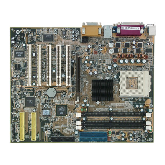
Page 9: Layout Diagram For Nv7-133R
Introduction of NV7-133R Features 1-4. Layout Diagram for NV7-133R Figure 1-1. NV7-133R motherboard component location User’s Manual... - Page 10 Chapter 1 NV7-133R...
-
Page 11: Chapter 2. Installing The Motherboard
Installing the Motherboard Chapter 2. Installing the Motherboard This NV7-133R motherboard not only provides all standard equipment for classic personal computers, but also provides great flexibility for meeting future upgrade demands. This chapter will introduce step by step all of the standard equipment and will also present, as completely as possible, future upgrade ™... -
Page 12: Installation Of The
Chapter 2 ™ ™ ™ 2-1. Installation of the AMD Athlon XP, Athlon and Duron Note ! Installing a heatsink and cooling fan is necessary for heat to dissipate from your processor. Failing to install these items may result in overheating and processor damage. ! The AMD Socket A processor will produce a lot of heat while operating, so you need to use a large heat sink that is especially designed for the AMD socket A processor. - Page 13 Installing the Motherboard Heatsink Installation Hints Because the processor will produce a lot of heat while operating, we suggest you use a heatsink approved by AMD to be safe and to keep the processor temperature within normal operation temperatures. The heatsink will be large and heavy, so the fixing plate has a strong tension.
- Page 14 Chapter 2 Insert a flat screwdriver into the middle slot of the right side fix plate and push down. Then you can push the fix plate over the socket hooks on the right side. Check the photo on the left. Check the photo on the left.
-
Page 15: Installing The Motherboard To The Chassis
Installing the Motherboard 2-2. Installing the Motherboard to the Chassis After you install the processor to the motherboard, you can start to fix the motherboard into the chassis. Most computer chassis will have a base on which there will be many mounting holes that allows the motherboard to be securely attached and at the same time, prevents short circuits. -
Page 16: Installing System Memory
Chapter 2 2-3. Installing System Memory This motherboard provides three 184-pin DDR DIMM sites for memory expansion. The DDR DIMM sockets support 8 M x 64 (64 MB), 16M x 64 (128 MB), 32 M x 64 (256 MB) and 64 M x 64 (512 MB) or double density DDR DIMM modules. -
Page 17: Connectors, Headers And Switches
Installing the Motherboard Figure 2-6 for the details. This insures the DDR DIMM module will be plugged into the socket in one way only. Firmly press the DDR DIMM module into DDR DIMM socket, making certain the module is completely seated in the DDR DIMM socket. Step 6. - Page 18 Chapter 2 Figure 2-7. All connectors and headers for the NV7-133R First, Let’s see the headers that NV7-133R uses, and what their functions are. We will show you all the connectors and headers. (1). ATXPWR1 and ATX12V1: ATX Power Input Connector NV7-133R requires a power supplier different from the regular one (Power supply designed for ®...
- Page 19 Installing the Motherboard Caution If the power supply connectors are not properly attached to the ATX power supply, the power supply or add-on cards may be damaged. One end of AC power core connects to ATX power supply, and the other end (AC plug) will plug into the wall outlet.
- Page 20 2-10 Chapter 2 (3). IR1: IR Header (Infrared) There is a specific orientation for pins 1 through 6, attach the connector from the IR KIT or IR device to the IR1 header. This motherboard supports standard IR transfer rates. Note: Watch the pin position and the orientation (4).
- Page 21 Installing the Motherboard 2-11 (5). RT1 & RT2: Processor & System Temperature Thermistor The RT1 is used to detect the processor temperature. The RT2 is used to detect the system environment temperature. You can see the readings in the BIOS or in the hardware monitoring application main screen.
- Page 22 2-12 Chapter 2 (7). CCMOS1 Header: CMOS Discharge Jumper Jumper CCMOS1 used to discharge CMOS memory. When you install the motherboard, make sure this jumper is set for normal operation (pin 1 and 2 shorted). See figure below. Note Before you clear the CMOS, you have to first turn the power off (including the +5V standby power). Otherwise, your system may work abnormally.
- Page 23 Installing the Motherboard 2-13 FPIO1 (Pin 5 & 7): Hardware Reset Switch Header Attach the cable from the case’s front panel Reset switch to this header. Press and hold the reset button for at least one second to reset the system. FPIO1 (Pin 15-17-19-21): Speaker Header Attach the cable from the system speaker to this header.
- Page 24 2-14 Chapter 2 (9). 6CHAUD1 Header: 6 Channels Audio Header You’ll see this header on NV7-133R motherboard. This header is designed to connect the CA-20. CA-20 can provide the analog audio output signals for center channel, subwoofer, rear right and rear left channel. It also provides one digital S/PDIF input and one digital S/PDIF output connector.
- Page 25 Installing the Motherboard 2-15 (11). FDC1 Connector This 34-pin connector is called the “floppy disk drive connector”. You can connect a 360K, 5.25”, 1.2M, 5.25”, 720K, 3.5’’, 1.44M, 3.5” or 2.88M, 3.5” floppy disk drive. A floppy disk drive ribbon cable has 34 wires and two connectors to provide the connection of two floppy disk drives.
- Page 26 2-16 Chapter 2 Figure 2-8. Ultra DMA 66 Ribbon Cable Outline Note ! The Master or Slave status of the hard disk drive is set on the hard disk itself. Please refer to the hard disk drive user’s manual. ! To connect Ultra DMA 100 devices on IDE1 and IDE2 or connect Ultra DMA 100 & Ultra DMA 133 devices on IDE3 and IDE4, an Ultra DMA 66 cable is required.
- Page 27 Installing the Motherboard 2-17 (14). PS/2 Mouse Connector Attach a PS/2 mouse to this 6-pin Din-connector. (15). Serial Port COM1 & COM2 Port Connectors This motherboard provides two COM ports, you can connect an external modem, mouse or other devices that support this communication protocol to these connectors.
- Page 28 2-18 Chapter 2 a built in amplifier, or you may not hear any sound or only a small volume of sound from the speaker. Line In Connector: You can connect the TV adapter audio output signal, or external audio sources, like a CD walkman, video camcorder, VHS recorder audio output signal plug to this connector.
-
Page 29: Introducing The Bios
Introducing the BIOS Chapter 3. Introducing the BIOS The BIOS is a program located on a Flash Memory chip on the motherboard. This program will not be lost when you turn the computer off. This program is also referred to as the boot program. It is the only channel the hardware circuit has to communicate with the operating system. - Page 30 Chapter 3 In the BIOS Setup main menu of Figure 3-1, you can see several options. We will explain these options step by step in the following pages of this chapter, but let us first see a short description of the function keys you may use here: Press Esc to quit the BIOS Setup.
-
Page 31: [Soft Menu ™ Ii]
Introducing the BIOS ™ 3-1. CPU Setup [SOFT MENU ™ The CPU can be setup through a programmable switch (CPU SOFT MENU II), that replaces the traditional manual hardware configuration. This feature allows the user to more easily complete the installation procedures. - Page 32 Chapter 3 FSB Ratio (CPU/ AGP): Two options are available: 3:2 ( 3:1.5 (When item “CPU EXT. CLK (CPU/AGP)” set between 100 MHz to 132 MHz) or 4:2 ( 4:1.5 (When item “CPU EXT. CLK (CPU/AGP)” set between 133 MHz or higher).
-
Page 33: Standard Cmos Features Setup Menu
Introducing the BIOS to use the CCMOS jumper to erase the parameters of the original CPU and to enter BIOS Setup to set up CPU parameters again. Attention After setting up the parameters and leaving the BIOS SETUP, and having verified that the system can be booted, do not press the Reset button or turn off the power supply. - Page 34 Chapter 3 Time (hh:mm:ss): You can set the time in this item: hour (hh), minute (mm) and second (ss). IDE Primary Master / Slave and IDE Secondary Master / Slave: These items have a sub-menu to let you choose further options. You can refer to figure 3-3B to check what options are available.
- Page 35 Introducing the BIOS Access Mode: Since old operating systems were only able to support HDDs with capacities no bigger than 528 MB, any hard disk with more than 528 MB was unusable. AWARD BIOS features a solution to this problem: you can, according to your operating system, choose four operating modes: NORMAL ( LBA ( LARGE (Auto.
- Page 36 Chapter 3 Warning Setting a value of 65536 means no hard disk exists. " Landing Zone: This is a non-data area on the disk's inner cylinder where the heads can rest when the power is turned off. The minimum number you can enter is 0, the maximum number you can enter is 65536. "...
-
Page 37: Advanced Bios Features Setup Menu
Introducing the BIOS 3-3. Advanced BIOS Features Setup Menu In each item, you can press <Enter> at any time to display all the options for this item. Attention Advanced BIOS Features Setup Menu has already been set for maximum operation. If you do not really understand each of the options in this menu, we recommend you use the default values. - Page 38 3-10 Chapter 3 CPU Level 2 Cache: Two options are available: Enabled or Disabled. The default setting is Enabled. This item is used to enable or to disable the CPU level 2 cache ECC checking function. Quick Power On Self Test: After the computer has been powered on, the BIOS of the motherboard will run a series of tests in order to check the system and its peripherals.
- Page 39 Introducing the BIOS 3-11 Typematic Rate Setting: This item allows you to adjust the keystroke repeat rate. When set to Enabled, you can set the two keyboard typematic controls that follow (Typematic Rate and Typematic Delay). If this item is set to Disabled, the BIOS will use the default setting.
-
Page 40: Advanced Chipset Features Setup Menu
3-12 Chapter 3 using another operating system, select Non-OS2. The default setting is Non-OS2. Report No FDD For WIN 95: ® When using Windows 95 without a floppy drive set this item to Yes. Otherwise, set it to No. The default setting is No. - Page 41 Introducing the BIOS 3-13 You can use the arrow keys to move between the items. Use PgUP, PgDn, + or - key to change the values. When you have finished setting up the chipset, press <ESC> to go back to the main menu. Note The parameters in this screen are for system designers, service personnel, and technically competent users only.
-
Page 42: Integrated Peripherals
3-14 Chapter 3 3-5. Integrated Peripherals In this menu, you can change the onboard I/O device, I/O port address and other hardware settings. Figure 3-6A. Integrated Peripherals Menu Upper Screen Figure 3-6B. Integrated Peripherals Menu Middle Screen NV7-133R... - Page 43 Introducing the BIOS 3-15 Figure 3-6C. Integrated Peripherals Menu Lower Screen Onboard IDE-1 Controller: The onboard IDE 1 controller can be set as Enabled or Disabled. The default setting is Enabled. Of course you can disable this item as well. The enable items will show as white color and disabled items will show blue green color.
- Page 44 3-16 Chapter 3 You first have to be sure that your IDE device supports this MODE. Otherwise, the hard disk will not be able to operate normally. IDE Prefetch Mode: Two options are available: Disabled or Enabled. The default setting is Enabled. The onboard IDE drive interfaces supports IDE prefetching for faster drive accesses.
- Page 45 Introducing the BIOS 3-17 MAC Lan: Two options are available: Disabled ( Auto. The default setting is Auto. This item can let you enable or disable the onboard LAN chip functions. Onboard USB 2.0 Controller: Two options are available: Disabled ( Enabled. The default setting is Enabled. This item can turn onboard USB 2.0 functions enable or disable.
- Page 46 3-18 Chapter 3 Onboard Serial Port 2: This item allows you to determine which I/O address the onboard serial port 2 controller will access. Six options are available: Disabled ( 3F8/IRQ4 ( 2F8/IRQ3 ( 3E8/IRQ4 ( 2E8/IRQ3 ( Auto (Back to Disabled.
-
Page 47: Power Management Setup Menu
Introducing the BIOS 3-19 Select SPP unless you are certain your hardware and software supports both EPP or ECP mode. According to your selection, the following items will appear. " EPP Mode Select: Two options are available: EPP1.9 ( EPP1.7. The default setting is EPP1.7. When the mode selected for the parallel port mode is EPP, the two EPP mode options are available. - Page 48 3-20 Chapter 3 Normal Mode ===> Doze Mode ===> Standby Mode ===> Suspend Mode The system consumption is reduced according the following sequence: Normal Doze > Standby Suspend > > 1. In the Main Menu, select “Power Management Setup” and press <Enter>. The following screen is displayed: Figure 3-7A.
- Page 49 Introducing the BIOS 3-21 ! Plug and Play (including bus and device enumeration) and APM functionality normally contained in the BIOS. ! Power management control of individual devices, add-in cards (some add-in cards may require an ACPI-aware driver), video displays, and hard disk drives. ! A Soft-off feature that enables the operating system to power off the computer.
- Page 50 3-22 Chapter 3 The S1 (POS) State (POS means Power On Suspend): While the system is in the S1 sleeping state, its behavior is as described below: ! The processor is not executing instructions. The processor’s complex context is maintained. ! Dynamic RAM context is maintained.
- Page 51 Introducing the BIOS 3-23 the computer is inactive during this period, the system will enter the Suspend power saving mode. The CPU stops working completely. There are three options for power management: ! User Define: “User Define” defines the delay for accessing the power modes. "...
-
Page 52: Pnp/Pci Configurations Setup Menu
3-24 Chapter 3 3-7. PnP/PCI Configurations Setup Menu In this menu, you can change the INT# and IRQ# of the PCI bus and other hardware settings. Figure 3-8A. PnP/PCI Configurations Setup Menu Force Update ESCD: Two options are available: Disabled or Enabled. The default setting is Disabled. Normally, you should leave this field Disabled. - Page 53 Introducing the BIOS 3-25 " IRQ Resources: If you have trouble in assigning the interrupt resources automatically, you can select Manual to set which IRQis assigned to which PCI Device or Reserved it. See the screen shot below.IRQ Resources: If you have trouble in assigning the interrupt resources automatically, you can select Manual to set which IRQis assigned to which PCI device or reserve it.
- Page 54 3-26 Chapter 3 PCI Latency Timer: The DEC (decimal) numbers from 0 to 255 are available, with the default setting at 32. This item can let you set the PCI latency clock delay time. Which means, you can set how many clocks you want it delay. PIRQ_0 Use IRQ No.
-
Page 55: Pc Health Status
Introducing the BIOS 3-27 3-8. PC Health Status You can set the warning and shutdown temperatures for your computer system, and you can check the fan speeds and power supply voltages of your computer system. The features are useful for monitoring all the important parameters within your computer system. -
Page 56: Load Fail-Safe Defaults
3-28 Chapter 3 Note The hardware monitoring features for temperatures, fans and voltages will occupy the I/O address from 294H to 297H. If you have a network adapter, sound card or other add-on cards that might use those I/O addresses, please adjust your add-on card I/O address, to avoid the use of those addresses. 3-9. -
Page 57: Save & Exit Setup
Introducing the BIOS 3-29 PASSWORD DISABLED. When a password has been enabled, you will be prompted to enter it every time you try to enter Setup. This prevents an unauthorized person from changing any part of your system configuration. Additionally, when a password is enabled, you can also require the BIOS to request a password every time your system is rebooted. - Page 58 3-30 Chapter 3 NV7-133R...
-
Page 59: Chapter 4. Raid Setting Guide
RAID Setting Guide Chapter 4. RAID Setting Guide For detail RAID introduce and concept, you can found it on our WEB site “Technological Terms”, or you can search the concerning information on internet. We do not description it on this manual. 4-1. -
Page 60: The Bios Setting Menu
Chapter 4 4-3. The BIOS Setting Menu Reboot your system. Press <CTRL> and <H> key while booting up the system to enter the BIOS setting menu. The main menu of BIOS Setting Utility appears as below: For selecting the option in the menu, you may: ! Press F1 to view array status. - Page 61 RAID Setting Guide After you had selected the function from the main menu, press the <Enter> key to enter the sub menu as shown below: Array Mode: This item allows you to select the appropriate RAID mode for the desired array. There are four modes to choose.
- Page 62 Chapter 4 Note When you choose to create RAID 1 and your source disk is not empty. You have to Duplicate Mirror Disk to copy the data to the destination disk. Otherwise, it will only copy the partition table to the destination disk, not the physical date.
- Page 63 RAID Setting Guide " Select Source Disk: This item is to select the source disk. The size of source disk must be smaller or equal to the target disk. " Select Target Disk: This item is to select the target disk. The size of target disk must be greater or equal to the one of source disk.
- Page 64 Chapter 4 4-3-7. OPTION 7: Set Boot Disk This item allows you to select the boot disk among the hard disk(s). Note This item will appear when necessary, not always appear. Use the up/down arrow to select the menu option to “Set Boot Disk” and press <Enter>. In the Channel Status, select the channel you would like to set as bootable disk and press <Enter>, an asterisk appears in the parentheses to indicate that the channel has been selected.
-
Page 65: Chapter 5. Dos
HPT 372 Driver Installation Chapter 5. HPT 372 Driver Installation Here we will show you the driver installation procedure under various operating systems. ® 5-1. DOS ® ® This IDE RAID BIOS supports DOS 5.x (or above) and Windows 3.1x without the software driver. ®... - Page 66 Chapter 5 Step 9: The “Digital Signature Not Found” Step 6: Program will start to install all drivers the menu appears. Click “Yes” to continue. system needs. The installer will show the install progress percentage. Step 7: Windows has completed installing the driver.
- Page 67 HPT370 Software Installation ® Installing the driver (During a fresh Windows 2000 installation) ® Note: Follow the standard procedures for installing Windows 2000. ® 1. During the first part of the setup procedure, Windows 2000 will prompt you to press “F6” key to specify an additional device.
- Page 68 Chapter 5 NV7-133R...
-
Page 69: Chapter 6. Hpt 372 Raid Administrator Installation Guide
HPT 372 RAID Administrator Installation Guide Chapter 6. HPT 372 RAID Administrator Installation Guide In order to enable the on-screen monitoring function displaying disk array device information, you may install the “HPT 372 RAID Administrator” onto your system. The main features of this administrator are described below: 1. - Page 70 Chapter 6 Step 8: When the installation is completed, Step 5: Now you can choose the folder for the choose “Yes, I want to restart my computer destination location you want. We suggest that now.” in the check box and click “Finish” to end you use the default folder as the destination location.
- Page 71 HPT 372 RAID Administrator Installation Guide icon. Now you are in the RAID Administrator screen. Your current device allocation is viewable at a glance. Move the cursor to the drive icon you want to view and click on it. The screen below shows you that two HDDs connected on to the HPT 372 controller. You can click on each HDD icon to get more information about each HDD.
- Page 72 Chapter 6 NV7-133R...
- Page 73 ® NVIDIA nForce Chipset Drivers Installation for Windows 2000 Appendix A. NVIDIA nForce Chipset Drivers ® Installation for Windows 2000 ® After you’ve installed Windows 2000, you will need to install the NVIDIA nForce chipset drivers. Step by step instructions on how to do this are found in the following section. Note ®...
- Page 74 Appendix A Step 3: You will now see the welcome screen Step 5: When the installation is complete, the and its dialogue box. Click “Next>” button to go installer will ask you to restart your computer. We suggest that you choose “Yes, I want to restart my computer now.”...
-
Page 75: Appendix A. Nvidia Nforce Chipset Drivers Installation For Windows ® 2000
® NVIDIA nForce Chipset Drivers Installation for Windows 2000 Step 7: When OS restart, you can then check the “Device Manager” to see that the devices are properly installed. User’s Manual... - Page 76 Appendix A NV7-133R...
-
Page 77: Appendix B. Installing The Winbond Hardware Doctor
Installing The Winbond Hardware Doctor Appendix B. Installing The Winbond Hardware Doctor The Winbond hardware doctor is a self-diagnostic system for PCs. It will protect PC hardware by monitoring several critical items including power supply voltage, CPU and system fan speeds, and CPU and system temperatures. - Page 78 Appendix B You will see the install shell wizard active. The welcome screen and its dialogue box will appear. Click the “Next>” button to go on. Now you can choose the destination location where you want to install the drivers. We suggest that you use the default folder as the destination location.
- Page 79 Installing The Winbond Hardware Doctor You can choose the name of the program folder. We suggest you use the default program folder name. After checking the program folder name then click “Next>” button. Program will start to install drivers the system needs.
- Page 80 Appendix B You can select the program from Start toolbar, and then choose Programs. You will see the item called “Winbond” ( “Hardware Doctor”. Click it, and you will be able to see the screen below. This screen shows the hardware monitor system screen.
-
Page 81: Appendix C. Usb 2.0 Drivers Installation For Windows
® USB 2.0 Drivers Installation for Windows 2000 Appendix C. USB 2.0 Drivers Installation for ® Windows 2000 This motherboard had built-in the USB 2.0 functions, can let you support the new generation USB 2.0 specification devices. The following description will tell you how to install the USB 2.0 drivers. Step 2: Choose “USB 2.0 Driver”... - Page 82 Appendix C your computer to finish the driver updates. Step 4: You will now see the welcome screen and its dialogue box. Click “Next>” button to go Step 7: Check the “Device Manager” to see that the USB controller device is properly installed. Step 5: Choose “Install USB 2.0 Driver”...
-
Page 83: Appendix D. Bios Update Guide
BIOS Update Guide Appendix D. BIOS Update Guide We will use the SE6 motherboard as an example. All other models follow the same process. First, know your motherboard’s model name and version number. You can find it on one slot or at the back of the motherboard. - Page 84 Appendix D 3. Download the correct BIOS file from our Web site. Go to our Web site and choose the correct BIOS file and download it. 4. Double click the download file, it will self-extract to .bin file. 5. Make a bootable floppy disk and copy the necessary files onto it. You may make a floppy disk bootable either in Explorer or in the DOS prompt mode.
- Page 85 BIOS Update Guide After formatting and transferring the system to the floppy disk, copy two files into it. One is the BIOS flash utility “awdflash.exe” and the other is the decompressed BIOS binary file. 6. Boot off floppy disk. User’s Manual...
- Page 86 Appendix D Please set the first boot sequence as “floppy” in BIOS and boot off the floppy disk. 7. Flash the BIOS in pure DOS mode. After successfully booting off of the floppy, execute the flash utility according to these instructions show below: A:\awdflash se6_sw.bin /cc /py /sn /r Note We strongly recommend you use the above parameters following “awdflash”...
-
Page 87: Appendix E. Troubleshooting (Need Assistance
Troubleshooting (Need Assistance?) Appendix E. Troubleshooting (Need Assistance?) Motherboard Troubleshooting: Q & A: Q: Do I need to clear the CMOS before I use a new motherboard to assemble my new computer system? A: Yes, we highly recommend that you clear the CMOS before installing a new motherboard. Please move the CMOS jumper from its default 1-2 position to 2-3 for a few seconds, and then back. - Page 88 Appendix E Example 2: With a system including: motherboard (with processor, DDR DRAM, etc.) HDD, CD-ROM, FDD, graphic adapter, MPEG-2 card, SCSI adapter, audio card, etc. After assembly and after having installed the audio card driver, when you restart the system, when it runs the audio card driver, it resets automatically.
- Page 89 Troubleshooting (Need Assistance?) . OS/Applications: Indicate the operating system and the applications you are running on the system. ® ® ® For example: Windows 98 SE, Windows 2000, Windows XP, etc. . Processor Type: Indicate the brand and the speed (MHz) of your CPU. ™...
- Page 90 Appendix E RAID Troubleshooting Q & A: Q: May I use hard drives with different capacity or transfer mode? A: In order to get optimized performance, we suggest using hard drives with the same model. Q: How to assign a booting device? A: You may press <Ctrl>...
- Page 91 Troubleshooting (Need Assistance?) Q: Why I see “NO ROM BASIC SYSTEM HALTED” when booting? A: There isn’t any activated primary partition in you system. Please use FDISK or any other utilities to create/set one. Do & Don’t: 1. Do always use the same model drives to achieve best quality and performance. Different firmware has different timing characteristic, thus may somewhat decrease the RAID performance.
- Page 92 Appendix E Technical Support Form 2 Phone Number: ! Company Name: " Contact Person: # Fax Number: 3 E-mail Address: Model Name BIOS ID & Part Number * Motherboard PCB Version Driver Version OS/Applications Hardware Name Brand Specifications Processor Type IDE1 Hard Disk Drive IDE2...
-
Page 93: Appendix F. How To Get Technical Support
Also please make sure you have the latest drivers from your peripheral cards makers! 3. Check the ABIT Technical Terms Guide and FAQ on our website. We are trying to expand and make the FAQs more helpful and information rich. Let us know if you have any suggestions. For hot topics check out our HOT FAQ! 4. - Page 94 5. Contacting ABIT. If you feel that you need to contact ABIT directly you can send email to the ABIT technical support department. First, please contact the support team for the branch office closest to you.
- Page 95 You should be able to get RMA service there. 6. Reporting Compatibility Problems to ABIT. Because of tremendous number of email messages we receive every day, we are forced to give greater weight to certain types of messages than to others.
- Page 96 Appendix F NV7-133R...
Need help?
Do you have a question about the AB-NV7-133R and is the answer not in the manual?
Questions and answers