Sign In
Upload
Download
Table of Contents
Contents
Add to my manuals
Delete from my manuals
Share
URL of this page:
HTML Link:
Bookmark this page
Add
Manual will be automatically added to "My Manuals"
Print this page
×
Bookmark added
×
Added to my manuals
Manuals
Brands
BC Biomedical Manuals
Medical Equipment
NIBP-1010
User manual
BC Biomedical NIBP-1010 User Manual
Non-invasive blood pressure simulators
Hide thumbs
1
2
Table Of Contents
3
4
5
6
7
8
9
10
11
12
13
14
15
16
17
18
19
20
21
22
23
24
25
26
27
28
29
30
31
32
33
34
35
36
37
38
39
40
41
42
43
44
45
46
47
48
page
of
48
Go
/
48
Contents
Table of Contents
Bookmarks
Table of Contents
Blood Pressure
Table of Contents
Description
Overview
Keys
Screens
Setup
Operations
Connecting Pressure Cuffs
Connecting Patient Leads
Ibp Connector (Nibp-1030 Only)
Temperature Connector (Nibp-1030 Only)
Aux Connector
Theory of Operations
Running a Test
Manual Revisions
Warranty
Specifications
Invasive Blood Pressure
Notes
Advertisement
Quick Links
1
Blood Pressure
2
Description
3
Setup
4
Connecting Pressure Cuffs
5
Running a Test
6
Specifications
Download this manual
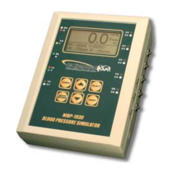
NON-INVASIVE
BLOOD PRESSURE
SIMULATORS
NIBP-1030
NIBP-1020
NIBP-1010
USER MANUAL
Table of
Contents
Previous
Page
Next
Page
1
2
3
4
5
Advertisement
Table of Contents
Need help?
Do you have a question about the NIBP-1010 and is the answer not in the manual?
Ask a question
Questions and answers
Related Manuals for BC Biomedical NIBP-1010
Medical Equipment BC Biomedical NIBP-1030 User Manual
Non-invasive blood pressure simulators (48 pages)
Medical Equipment BC Biomedical NIBP-1020 User Manual
Non-invasive blood pressure simulators (48 pages)
Medical Equipment BC Biomedical ENDOCHECK Test system User Manual
Test system (8 pages)
Medical Equipment BC Biomedical FINGERSIM PULSE OXIMETER TEST SYSTEM Instruction And Service Manual
Pulse oximeter test system (13 pages)
Medical Equipment BC Biomedical MAXISIM 2000 User Manual
Patient simulator (11 pages)
Medical Equipment BC Biomedical ESU-2000 Series Guide Manual
Esu analyzer (52 pages)
Medical Equipment BC Biomedical PLA User Manual
Pacer load adapter (8 pages)
Medical Equipment BC Biomedical PS-2200 series User Manual
Multi-parameter patient simulator (85 pages)
Medical Equipment BC Biomedical PS-2110 User Manual
Multi-parameter patient simulator (47 pages)
Medical Equipment BC Biomedical PS-2105 User Manual
Multi-parameter patient simulator (48 pages)
Medical Equipment BC Biomedical Auxiliary ESU Load Resistor User Instructions
For use with bc biomedical esu-2000a esu analyzer (1 page)
This manual is also suitable for:
Nibp-1030
Nibp-1020
Table of Contents
Print
Rename the bookmark
Delete bookmark?
Delete from my manuals?
Login
Sign In
OR
Sign in with Facebook
Sign in with Google
Upload manual
Upload from disk
Upload from URL


Need help?
Do you have a question about the NIBP-1010 and is the answer not in the manual?
Questions and answers