Sign In
Upload
Download
Table of Contents
Contents
Add to my manuals
Delete from my manuals
Share
URL of this page:
HTML Link:
Bookmark this page
Add
Manual will be automatically added to "My Manuals"
Print this page
×
Bookmark added
×
Added to my manuals
Manuals
Brands
Bosch Manuals
Conference System
DCN-DS
Installation and operation manual
Bosch DCN-DS Installation And Operation Manual
Dcn-d conference delegate units
Hide thumbs
1
2
Table Of Contents
3
4
5
6
7
8
9
10
11
12
13
14
15
16
17
18
19
20
21
22
23
24
25
26
page
of
26
Go
/
26
Contents
Table of Contents
Troubleshooting
Bookmarks
Table of Contents
Table of Contents
Safety
About this Manual
Digital Document
Alerts and Notice Signs
Introduction and Overview
Planning and Design
Limits
Power Consumption
Installation
Microphone Buttons
Remove the Microphone Button
Install the Priority and Microphone Button
Installation to a Flat Surface
Connection
Configuration
Initialization
De-Initialization
Internal Settings
Microphone Sensitivity
Channel/Volume Restore Function
Headphones Level Reduction
Delegate Unit Modes
Single Delegate
Chairman
Single Delegate with Auxiliary Control
Operation
Microphone
Attendance LED
Troubleshooting
Delegate Unit
Maintenance
Cleaning
Storage
Technical Data
Advertisement
Quick Links
1
Table of Contents
2
Introduction and Overview
3
Installation
4
Microphone Buttons
5
Connection
6
Configuration
7
Delegate Unit Modes
8
Chairman
Download this manual
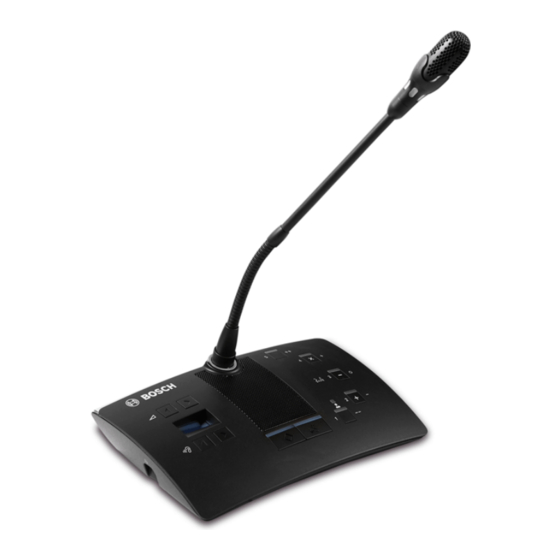
DCN-D Conference Delegate Units
DCN-DS/L, DCN-DCS, DCN-DV, DCN-DVCS
en
Installation and Operation manual
Table of
Contents
Previous
Page
Next
Page
1
2
3
4
5
Advertisement
Table of Contents
Need help?
Do you have a question about the DCN-DS and is the answer not in the manual?
Ask a question
Questions and answers
Related Manuals for Bosch DCN-DS
Conference System Bosch DCN multimedia Hardware Installation Manual
(32 pages)
Conference System Bosch DCN multimedia User Manual
(16 pages)
Conference System Bosch Digital Congress Network Data Brochure
Digital congress network data brochure (104 pages)
Conference System Bosch DCN multimedia User Manual
(24 pages)
Conference System Bosch DCN-L Installation And Operation Manual
Dcn-d conference delegate units (26 pages)
Conference System Bosch DCN-DCS Installation And Operation Manual
Dcn-d conference delegate units (26 pages)
Conference System Bosch DCN Next Generation Installation And Operation Manual
(286 pages)
Conference System Bosch DCN Next Generation Operation Manual
(290 pages)
Conference System Bosch DCN-DIS Quick Reference Card
Discussion unit (dual delegate) (2 pages)
Conference System Bosch DCN-DIS Quick Reference Card
Discussion unit (chairman) (2 pages)
Conference System Bosch DCN-DIS Quick Start Manual
Discussion unit (single delegate) (2 pages)
Conference System Bosch DCN-CONCM Concentus Quick Reference Manual
(2 pages)
Conference System Bosch DCN-CON Concentus Delegate Unit Quick Reference Card
(2 pages)
Conference System Bosch DICENTIS Hardware Installation Manual
(80 pages)
Conference System Bosch DCN-WD Quick Reference Card
Wireless discussion unit (chairman) (2 pages)
Conference System Bosch DCN-WD Quick Reference Card
Wireless discussion unit (single delegate) (2 pages)
This manual is also suitable for:
Dcn-l
Dcn-dcs
Dcn-dv
Dcn-dvcs
Table of Contents
Print
Rename the bookmark
Delete bookmark?
Delete from my manuals?
Login
Sign In
OR
Sign in with Facebook
Sign in with Google
Upload manual
Upload from disk
Upload from URL


Need help?
Do you have a question about the DCN-DS and is the answer not in the manual?
Questions and answers