Table of Contents
Advertisement
Quick Links
Download this manual
See also:
Configuration Manual
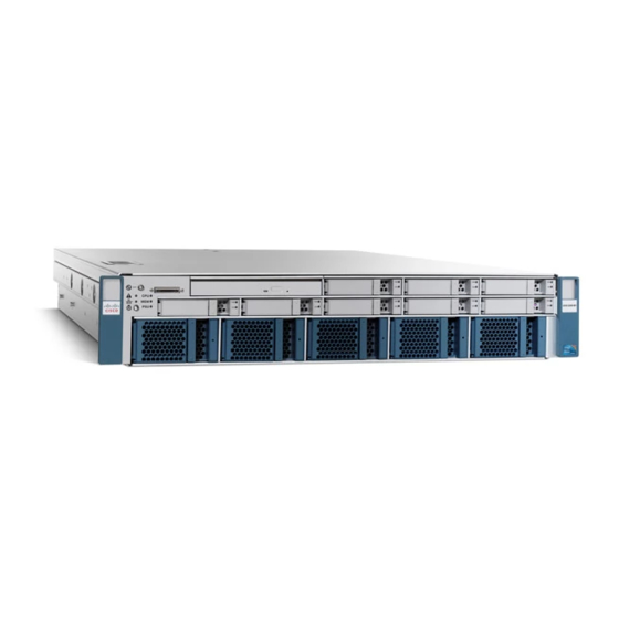
Cisco UCS C250 Server
Installation and Service Guide
Covers UCS C250 Server Generations M1 and M2
July 31, 2013
Americas Headquarters
Cisco Systems, Inc.
170 West Tasman Drive
San Jose, CA 95134-1706
USA
http://www.cisco.com
Tel: 408 526-4000
800 553-NETS (6387)
Fax: 408 527-0883
Text Part Number: OL-20888-02
Advertisement
Table of Contents

Related Manuals for Cisco UCS C250


Summary of Contents for Cisco UCS C250
- Page 1 Cisco UCS C250 Server Installation and Service Guide Covers UCS C250 Server Generations M1 and M2 July 31, 2013 Americas Headquarters Cisco Systems, Inc. 170 West Tasman Drive San Jose, CA 95134-1706 http://www.cisco.com Tel: 408 526-4000 800 553-NETS (6387) Fax: 408 527-0883...
- Page 2 Modifications to this product not authorized by Cisco could void the FCC approval and negate your authority to operate the product. The Cisco implementation of TCP header compression is an adaptation of a program developed by the University of California, Berkeley (UCB) as part of UCB’s public domain version of the UNIX operating system.
-
Page 3: Table Of Contents
Using a Clear CMOS Jumper on Header P35 2-17 Maintaining the Server C H A P T E R Server Monitoring and Management Tools Cisco Integrated Management Interface (CIMC) Server Configuration Utility Status LEDs Cisco UCS C250 Server Installation and Service Guide OL-20888-02... - Page 4 Replacing a PCIe Riser Card Assembly 3-31 Installing a PCIe Card 3-33 Replacement Procedure 3-34 Special Considerations for the Cisco UCS P81E Virtual Interface Card (N2XX-ACPCI01) 3-35 Installing Multiple PCIe Cards and Resolving Limited Resources 3-36 Replacing an LSI Battery Backup Unit 3-38...
- Page 5 How To Launch Option ROM-Based Controller Utilities Restoring RAID Configuration After Replacing a RAID Controller For More Information Installation for Cisco UCS Integration A P P E N D I X Cisco UCS C250 Server Installation and Service Guide OL-20888-02...
- Page 6 Contents Cisco UCS C250 Server Installation and Service Guide OL-20888-02...
-
Page 7: Related Documentation
This preface describes the audience, organization, and conventions of the Cisco UCS C250 Server Installation and Service Guide. It also provides information on how to obtain related documentation. This guide covers UCS C250 Server Generations M1 and M2. Differences between the generations are noted in text. - Page 8 Gebruik het nummer van de verklaring onderaan de waarschuwing als u een vertaling van de waarschuwing die bij het apparaat wordt geleverd, wilt raadplegen. BEWAAR DEZE INSTRUCTIES Cisco UCS C250 Server Installation and Service Guide viii OL-20888-02...
- Page 9 å forhindre ulykker. Bruk nummeret i slutten av hver advarsel for å finne oversettelsen i de oversatte sikkerhetsadvarslene som fulgte med denne enheten. TA VARE PÅ DISSE INSTRUKSJONENE Cisco UCS C250 Server Installation and Service Guide OL-20888-02...
- Page 10 Använd det nummer som finns i slutet av varje varning för att hitta dess översättning i de översatta säkerhetsvarningar som medföljer denna anordning. SPARA DESSA ANVISNINGAR Cisco UCS C250 Server Installation and Service Guide OL-20888-02...
- Page 11 Brug erklæringsnummeret efter hver advarsel for at finde oversættelsen i de oversatte advarsler, der fulgte med denne enhed. GEM DISSE ANVISNINGER Cisco UCS C250 Server Installation and Service Guide OL-20888-02...
- Page 12 Preface Cisco UCS C250 Server Installation and Service Guide OL-20888-02...
-
Page 13: Obtaining Documentation And Submitting A Service Request
Obtaining Documentation and Submitting a Service Request For information on obtaining documentation, submitting a service request, and gathering additional information, see the monthly What’s New in Cisco Product Documentation, which also lists all new and revised Cisco technical documentation, at: http://www.cisco.com/en/US/docs/general/whatsnew/whatsnew.html... - Page 14 Preface Cisco UCS C250 Server Installation and Service Guide OL-20888-02...
- Page 15 C H A P T E R Overview The Cisco UCS C250 server, which is a part of the Cisco UCS C-Series Rack-Mount Server family, operates in a wide range of data center environments, including those environments that use the Cisco Unified Computing System, Cisco Nexus family products, and discrete Ethernet and Fibre Channel switches from Cisco and third parties.
- Page 16 10/100 Ethernet management port M1 10/100 Ethernet management port M2 10 Power supply (up to two) Table 1-1 lists the hardware components and features of the The Cisco UCS C250 server: Table 1-1 Hardware Features of the Server Feature or...
-
Page 17: Chapter 1 Overview
7. VGA = video graphics array 8. USB = universal serial bus 9. KVM = keyboard, video, mouse See also the “Technical Specifications” section on page A-1 for more physical, environmental, and power details. Cisco UCS C250 Server Installation and Service Guide OL-20888-02... - Page 18 Chapter 1 Overview Cisco UCS C250 Server Installation and Service Guide OL-20888-02...
-
Page 19: Installing The Server
Statement 1030 This unit might have more than one power cord. To reduce the risk of electric shock, disconnect the Warning two power supply cords before servicing the unit. Statement 14 Cisco UCS C250 Server Installation and Service Guide OL-20888-02... -
Page 20: Chapter 2 Installing The Server
Model and serial number of the damaged unit Description of damage • Effect of damage on the installation • Figure 2-1 Shipping Box Contents Server Drivers and Utilities disc Power cord (optional, up to two) Documentation KVM cable Cisco UCS C250 Server Installation and Service Guide OL-20888-02... -
Page 21: Preparing For Installation
Avoid UPS types that use ferroresonant technology. These UPS types can become unstable with systems Caution such as the Cisco UCS, which can have substantial current draw fluctuations from fluctuating data traffic patterns. Cisco UCS C250 Server Installation and Service Guide... -
Page 22: Rack Requirements
Cisco. Required Equipment The slide rails supplied by Cisco Systems do not require any tools for installation, but you might want to use a tape measure and level to help level the slide rails during installation. -
Page 23: Installing The Server Into A Rack
Pull the inner slide rails on each assembly out toward the rack front until they hit the internal stops and lock in place. Cisco UCS C250 Server Installation and Service Guide OL-20888-02... - Page 24 You can install two of these screws on each side of the server to more permanently attach the mounting brackets to each side of the server, but they are not required. Cisco UCS C250 Server Installation and Service Guide OL-20888-02...
- Page 25 Slide the innermost CMA attachment clip (item 4) into the rear of the left slide rail (item 3) and clip it onto the CMA flange that is on the mounting bracket that is attached to the server. Cisco UCS C250 Server Installation and Service Guide OL-20888-02...
- Page 26 Innermost CMA attachment clip Two-hole slotted bracket on end of CMA Outermost CMA attachment clip length-adjustment slider Continue with the “Connecting and Powering On the Server (Standalone Mode)” section on page 2-9. Step 5 Cisco UCS C250 Server Installation and Service Guide OL-20888-02...
-
Page 27: Initial Server Setup
Cisco Integrated Management Interface (CIMC). If you want to use the 10/100 management ports or a Cisco network adapter card port to access the CIMC, you must first connect to the server and change the NIC mode as described in Step 3 of the following procedure. - Page 28 Port M1—DHCP is enabled, with no NIC redundancy. Port M2—Static IP address is 10.1.1.7, with no NIC redundancy. Cisco Card—The ports on an installed Cisco network adapter card are used to access the CIMC. – You have to select a NIC redundancy and IP setting.
- Page 29 Cisco Step 6 UCS C-Series Rack-Mount Server CLI Configuration Guide for instructions on using those interfaces. The links to these documents are in the C-Series documentation roadmap: http://www.cisco.com/go/unifiedcomputing/c-series-doc Cisco UCS C250 Server Installation and Service Guide 2-11 OL-20888-02...
-
Page 30: Nic Modes And Nic Redundancy Settings
Port M2—Static IP address is 10.1.1.7, with no NIC redundancy. – • Cisco Card—The ports on an installed Cisco network adapter card are used to access the CIMC. You have to select a NIC redundancy and IP setting. Note The Cisco Card NIC mode is currently supported only with a Cisco UCS P81E Virtual Interface... -
Page 31: System Bios And Cimc Firmware
Your system firmware must be at minimum level 1.2 to use the Cisco Host Upgrade Utility. If Note your firmware is prior to level 1.2, you must use the methods below to update the BIOS and CIMC firmware individually. -
Page 32: Accessing The System Bios
This unit might have more than one power cord. To reduce the risk of electric shock, disconnect the two power supply cords before servicing the unit. Statement 14 Figure 2-5 Service Jumper Location Location of P35 header (20-pin header on front edge of motherboard) Cisco UCS C250 Server Installation and Service Guide 2-14 OL-20888-02... -
Page 33: Using A Bios Recovery Jumper On Header P35
Reinstall the air baffle and the top cover. Step 15 Replace the server in the rack, replace power cords and any other cables, then power on the server by pressing the Power button. Cisco UCS C250 Server Installation and Service Guide 2-15 OL-20888-02... -
Page 34: Using A Clear Bios Admin Password Jumper On Header P35
Reinstall the air baffle and the top cover. Step 13 Replace the server in the rack, replace power cords and any other cables, then power on the server by pressing the Power button. Cisco UCS C250 Server Installation and Service Guide 2-16 OL-20888-02... -
Page 35: Using A Clear Cmos Jumper On Header P35
Reinstall the air baffle and the top cover. Step 12 Replace the server in the rack, replace power cords and any other cables, then power on the server by Step 13 pressing the Power button. Cisco UCS C250 Server Installation and Service Guide 2-17 OL-20888-02... - Page 36 Chapter 2 Installing the Server System BIOS and CIMC Firmware Cisco UCS C250 Server Installation and Service Guide 2-18 OL-20888-02...
-
Page 37: Server Monitoring And Management Tools
Configuring some RAID configurations • Installing operating systems This utility is shipped with new servers on CD. You can also download the ISO from Cisco.com. See the user documentation for this utility at the following URL: http://www.cisco.com/en/US/docs/unified_computing/ucs/sw/ucsscu/user/guide/20/SCUUG20.html Cisco UCS C250 Server Installation and Service Guide... -
Page 38: Chapter 3 Maintaining The Server
(for example, overheating). In most cases, the moderate fault self-corrects, at which time the LED returns to normal state. A “severe fault” is a fault that requires immediate service action. Cisco UCS C250 Server Installation and Service Guide OL-20888-02... - Page 39 • Hard drive activity • Off—There is no hard drive in the hard drive sled. • Green—The hard drive is ready. • Green, blinking—The hard drive is reading or writing data. Cisco UCS C250 Server Installation and Service Guide OL-20888-02...
- Page 40 Off—The hard drive is operating properly. • Amber—This hard drive has failed. • Amber, blinking—The device is rebuilding. • Fan module fault Off—The fan module is operating properly. • Amber—This fan module has failed. • Cisco UCS C250 Server Installation and Service Guide OL-20888-02...
-
Page 41: Rear Panel Leds
LEDs and sensors to isolate the problem. • Amber, blinking—A severe fault event that requires immediate service action has been detected. Investigate other LEDs and sensors to isolate the problem. Cisco UCS C250 Server Installation and Service Guide OL-20888-02... - Page 42 “Connecting and Powering On the Server (Standalone Mode)” section on page 2-9 for definitions of these power modes. The 10/100 Ethernet link status LED and the speed LED must be read in Note combination for the following interpretations. Cisco UCS C250 Server Installation and Service Guide OL-20888-02...
- Page 43 • 10-Mbps link is present. Link status green + speed blinking green—A full-duplex, • 100-Mbps link is present. Link status amber + speed blinking green—A full-duplex, • 1000-Mbps link is present. Cisco UCS C250 Server Installation and Service Guide OL-20888-02...
-
Page 44: Preparing For Component Installation
The following items are used to perform the procedures in this chapter: Number 2 Phillips-head screwdriver • Number 1 Phillips-head screwdriver • Needle-nose pliers • Electrostatic discharge (ESD) strap or other grounding equipment such as a grounded mat. • Cisco UCS C250 Server Installation and Service Guide OL-20888-02... -
Page 45: Shutting Down And Powering Off The Server
Emergency shutdown—Press and hold the Power button for 4 seconds to force the main power off • and immediately enter standby mode. Disconnect the power cords from the power supplies in your server to completely power off the server. Step 3 Cisco UCS C250 Server Installation and Service Guide OL-20888-02... -
Page 46: Removing And Replacing The Server Top Cover
Push the release latch to the flat, closed position. Use a screwdriver to return the locking screw to the locked position. Figure 3-3 Removing the Top Cover Release latch Locking screw Cisco UCS C250 Server Installation and Service Guide 3-10 OL-20888-02... -
Page 47: Replaceable Component Locations
PCIe riser card assembly (with chassis slots in this view for two standard-profile cards) (active in server Generation M2 only) 10 PCIe riser card assembly (with chassis slots Motherboard CMOS battery for three low-profile cards) Cisco UCS C250 Server Installation and Service Guide 3-11 OL-20888-02... -
Page 48: Installing Or Replacing Components
Installing a Motherboard CMOS Battery, page 3-30 • Replacing a PCIe Riser Card Assembly, page 3-31 • Installing a PCIe Card, page 3-33 Replacing an LSI Battery Backup Unit, page 3-38 • Cisco UCS C250 Server Installation and Service Guide 3-12 OL-20888-02... -
Page 49: Installing Hard Drives And Solid State Drives
The 500 GB SATA drives (A03-D500GC3) and the 1 TB SATA drives (A03-D1TBSATA) that are sold Note with the UCS C250 M2 server are supported at 3G speeds. These are 6G drives and might possibly run faster than 3G in this server, but they are supported to run at minimum 3G speeds. - Page 50 Hard Drive/SSD CIMC Numbering and Physical Orientation, Facing Server Front HDD_01 HDD_02 HDD_03 HDD_04 HDD_05 HDD_06 HDD_07 HDD_08 Figure 3-6 Removing and Replacing Drives Release button Ejector lever Securing screws (four on sides of sled) Cisco UCS C250 Server Installation and Service Guide 3-14 OL-20888-02...
-
Page 51: Installing Fan Modules
Press the Power button to return the server to main power mode. Figure 3-7 Fan Module CIMC Numbering and Physical Orientation, Facing Server Front fantray-0 fantray-1 fantray-2 fantray-3 fantray-4 Figure 3-8 Removing and Replacing Fan Modules Release button Ejector lever Cisco UCS C250 Server Installation and Service Guide 3-15 OL-20888-02... -
Page 52: Installing Power Supplies
Figure 3-9 Power Supply CIMC Numbering and Physical Orientation, Facing Server Rear PSU1 PSU0 Figure 3-10 Removing and Replacing a Power Supply PSU1 PSU1 PSU0 PSU0 Release lever Power supply handle Cisco UCS C250 Server Installation and Service Guide 3-16 OL-20888-02... -
Page 53: Installing A Dvd Drive
Replace the cable to the connector on the rear of the DVD drive. Replace the top cover. Replace the server in the rack, replace power cords and any other cables, then power on the server by pressing the Power button. Cisco UCS C250 Server Installation and Service Guide 3-17 OL-20888-02... - Page 54 Chapter 3 Maintaining the Server Installing or Replacing Components Figure 3-11 Removing and Replacing a DVD drive DVD drive (shown with top cover removed) DVD cable connector DVD securing screw (one) Cisco UCS C250 Server Installation and Service Guide 3-18 OL-20888-02...
-
Page 55: Installing Dimms
Each bank is identified by numbers, 0 through 7. For example, DIMM slots A1, B1, and C1 belong to Bank 1, while A2, B2, C2 belong to Bank 2. Figure 3-12 shows how DIMM slot banks and channels are physically arranged on the motherboard. Cisco UCS C250 Server Installation and Service Guide 3-19 OL-20888-02... -
Page 56: Front Of Server
C7 C6 C1 C0 CPU 2 F0 F1 F6 F7 F3 F2 F5 F4 D0 D1 D6 D7 D3 D2 D5 D4 E0 E1 E6 E7 E3 E2 E5 E4 Front of Server Cisco UCS C250 Server Installation and Service Guide 3-20 OL-20888-02... - Page 57 3-20, B4 and B5 are side-by-side blue slots controlled by CPU1; E4 and E5 are side-by-side blue slots controlled by CPU2. The two DIMMs within a DIMM pair must have the identical manufacturer, type, speed, and size. Cisco • provides spare DIMMs for this product in matched pair kits.
- Page 58 (eight 4GB DIMMs) plus plus Eight 16GB pair-kits Eight 16GB pair-kits (sixteen 8GB DIMMs) (sixteen 8GB DIMMs) 384GB Twelve 16GB pair-kits Twelve 16GB pair-kits (twenty-four 8GB DIMMs) (twenty-four 8GB DIMMs) Cisco UCS C250 Server Installation and Service Guide 3-22 OL-20888-02...
- Page 59 Then populate the DIMM slots as shown in Table 3-4. The 4-, 8-, or 12-DIMM configurations are not supported in UCS C250 Generation M2 servers. Note The 4-, 8-, or 12-DIMM configurations are supported in UCS C250 Generation M1 only.
- Page 60 The two low-voltage DIMMs within a DIMM pair must have the identical manufacturer, type, speed, • and size. Cisco provides spare DIMMs for this product in matched pair kits. • Low-voltage DIMM pairs and standard-voltage DIMM pairs can be mixed in the same server. Note that this causes the system BIOS to default to standard-voltage operation (Performance Mode).
-
Page 61: Dimm Installation Procedure
Replace the air baffle and the top cover. Replace the server in the rack, replace power cords and any other cables, and then power on the server by pressing the Power button. Cisco UCS C250 Server Installation and Service Guide 3-25 OL-20888-02... - Page 62 Chapter 3 Maintaining the Server Installing or Replacing Components Figure 3-13 Removing and Replacing Memory Modules DIMM slot ejector lever (two on each slot) Alignment key in DIMM slot Cisco UCS C250 Server Installation and Service Guide 3-26 OL-20888-02...
-
Page 63: Installing Cpus And Heatsinks
Additional CPU-Related Parts To Order With RMA Replacement Motherboards When a return material authorization (RMA) of the motherboard or CPU is done on a Cisco UCS C-series server, there are additional parts that might not be included with the CPU or motherboard spare bill of materials (BOM). - Page 64 Replace the air baffle and the top cover. Replace the server in the rack, replace power cords and any other cables, and then power on the server by pressing the Power button. Cisco UCS C250 Server Installation and Service Guide 3-28 OL-20888-02...
- Page 65 Removing and Replacing CPUs and Heatsinks Captive heatsink screws (four per CPU) CPU heatsink CPU socket latch (open) CPU socket cover plate (open) CPU socket alignment key (both sides of CPU) Cisco UCS C250 Server Installation and Service Guide 3-29 OL-20888-02...
-
Page 66: Installing A Motherboard Cmos Battery
The flat, positive side of the battery marked with “+” must face the outer chassis wall. Note Replace the top cover. Replace the server in the rack, replace power cords and any other cables, and then power on the server by pressing the Power button. Cisco UCS C250 Server Installation and Service Guide 3-30 OL-20888-02... -
Page 67: Replacing A Pcie Riser Card Assembly
If you cannot safely view and access the component, remove the server from the rack. Caution Remove the top cover as described in the “Removing and Replacing the Server Top Cover” section on page 3-10. Cisco UCS C250 Server Installation and Service Guide 3-31 OL-20888-02... - Page 68 Replace the server in the rack, replace power cords and any other cables, and then power on the server by pressing the Power button. Figure 3-16 Removing and Replacing a PCIe Riser Card Assembly Riser card retaining plate Riser card assembly (standard profile) Cisco UCS C250 Server Installation and Service Guide 3-32 OL-20888-02...
-
Page 69: Installing A Pcie Card
For more information about RAID controllers and cables, see also RAID Controller Considerations, Note page C-1. If you are installing a Cisco UCS P81E Virtual Interface Card (N2XX-ACPCI01), there are prerequisite Note considerations. See Special Considerations for the Cisco UCS P81E Virtual Interface Card (N2XX-ACPCI01), page 3-35. -
Page 70: Replacement Procedure
Replace the top cover. Replace the server in the rack, replace power cords and any other cables, and then power on the server by pressing the Power button. Cisco UCS C250 Server Installation and Service Guide 3-34 OL-20888-02... -
Page 71: Special Considerations For The Cisco Ucs P81E Virtual Interface Card (N2Xx-Acpci01)
This server supports installation of up to two of these cards. • • These cards are supported only in PCIe slots D and E of this server. This card must be installed in PCIe slot D to use the Cisco Card NIC mode (see Figure 3-17 on Note page 3-33). -
Page 72: Installing Multiple Pcie Cards And Resolving Limited Resources
ROMs for the onboard NICs to be booted from are enabled in the BIOS Setup Utility. Disable other option ROMs that are not needed to create sufficient memory space for the onboard NICs. Cisco UCS C250 Server Installation and Service Guide 3-36... - Page 73 Physically remove any unused PCIe cards. If the system has one or more Cisco virtual interface cards (VICs) installed, disable the PXE boot on the VICs that are not required for the system boot configuration by using the Network Adapters page in the CIMC WebUI to free up some 16-bit I/O resources.
-
Page 74: Replacing An Lsi Battery Backup Unit
A cable is shipped with the BBU that is used for installing the BBU on a bracket in other server models. Do not use this cable in the Cisco UCS C250 server; install the BBU directly onto the LSI controller card. -
Page 75: Appendix
A P P E N D I X Technical Specifications This appendix lists the technical specifications for the Cisco UCS C250 server and includes the following sections: Physical Specifications, page A-1 • Environmental Specifications, page A-2 • Power Specifications, page A-2 •... -
Page 76: Environmental Specifications
Power Supply Information Maximum hold-up time 12 ms Efficiency rating Climate Savers Gold You can get more specific power information for your exact server configuration by using the Cisco UCS Power Calculator: http://www.cisco.com/assets/cdc_content_elements/flash/dataCenter/cisco_ucs_power_calculator/ Cisco UCS C250 Server Installation and Service Guide OL-20888-02... -
Page 77: Appendix
Power Cord, 250 VAC 10 A M 2511 Plug Europe SFS-250V-10A-ID Figure B-5 Power Cord, 250 VAC 16A EL-208 Plug South Africa, United Arab Emirates, India SFS-250V-10A-IS Figure B-6 Power Cord, 250 VAC 10 A SI32 Plug Israel Cisco UCS C250 Server Installation and Service Guide OL-26646-01... -
Page 78: Supported Power Cords And Plugs
Cabinet Jumper Power Cord, 250 VAC 10 A, C13-C14 Connectors CAB-C13-C14-2M Figure B-14 Cabinet Jumper Power Cord, 250 VAC 10 A, C13-C14 Connectors CAB-C13-C14-AC Figure B-15 Cabinet Jumper Power Cord, 250 VAC 10 A, C13-C14 Connectors Cisco UCS C250 Server Installation and Service Guide OL-26646-01... -
Page 79: Appendix B Power Cord Specification
Cordset rating: 10 A, 250 V/500V Length: 2500mm Connector: Plug: EL 701C EL 206 (IEC 60320/C15) A.S. 3112-2000) Figure B-3 SFS-250V-10A-CN Cordset rating 10A, 250V Plug: (2500 mm) EL 218 (CCEE GB2009) Connector: EL 701 (IEC60320/C13) Cisco UCS C250 Server Installation and Service Guide OL-26646-01... - Page 80 Figure B-5 SFS-250V-10A-ID Cordset rating 16A, 250V Plug: (2500mm) EL 208 Connector: EL 701 Figure B-6 SFS-250V-10A-IS Cordset rating 10A, 250V/500V MAX (2500 mm) Connector: EL 701B Plug: (IEC60320/C13) EL 212 (SI-32) Cisco UCS C250 Server Installation and Service Guide OL-26646-01...
- Page 81 MP232-R Connector: IEC 60320 C15 Figure B-9 CAB-9K10A-UK Cordset rating: 10 A, 250 V/500 V MAX Length: 2500mm Connector: EL 701C Plug: EL 210 (EN 60320/C15) (BS 1363A) 13 AMP fuse Cisco UCS C250 Server Installation and Service Guide OL-26646-01...
- Page 82 Figure B-11 CAB-N5K6A-NA Cordset rating: 10 A, 250 V Length: 8.2 ft Plug: NEMA 6-15P Connector: IEC60320/C13 Figure B-12 CAB-9K12A-NA Cordset rating 13A, 125V (8.2 feet) (2.5m) Plug: Connector: IEC60320/C15 NEMA 5-15P Cisco UCS C250 Server Installation and Service Guide OL-26646-01...
- Page 83 CAB-C13-C14-2M, Jumper Power Cord (2 m) Cordset rating 10A, 250V (2.0 m) Connector: Plug: HS10S SS10A Figure B-15 CAB-C13-C14-AC, Jumper Power Cord (3 m) Cordset rating 10A, 250V (3.0 m) Connector: Plug: HS10S SS10A Cisco UCS C250 Server Installation and Service Guide OL-26646-01...
- Page 84 Appendix B Power Cord Specifications Supported Power Cords and Plugs Cisco UCS C250 Server Installation and Service Guide OL-26646-01...
-
Page 85: Appendix
1. You can mix SAS and SATA drives when using an LSI SAS3081E-R card. However, you cannot mix SAS and SATA drives within a volume. 2. You can mix SAS and SATA drives when using an LSI MegaRAID card. However, you cannot mix SAS and SATA drives within a volume. Cisco UCS C250 Server Installation and Service Guide OL-20888-02... -
Page 86: A P P E N D I X C Raid Controller Considerations
The red line in Figure C-1 shows the recommended cable routing path from the backplane to the possible controller locations. Figure C-1 RAID Controller Cabling 1 Drive backplane 2 PCIe risers for controller cards Cisco UCS C250 Server Installation and Service Guide OL-20888-02... -
Page 87: Cisco Ucs C250 Server Cabling
Ctrl-H to launch configuration utilities for those cards. For servers running CIMC firmware earlier than release 1.2(1), see also How to Disable Quiet Boot For CIMC Firmware Earlier Than Release 1.2(1), page C-4. Cisco UCS C250 Server Installation and Service Guide OL-20888-02... -
Page 88: How To Disable Quiet Boot For Cimc Firmware Earlier Than Release 1.2(1
Note you in setting up some RAID configurations for your drives. This utility is shipped with new servers on CD. You can also download the ISO from Cisco.com. See the user documentation for this utility at the following URL: http://www.cisco.com/en/US/docs/unified_computing/ucs/sw/ucsscu/user/guide/20/SCUUG20.html... -
Page 89: Restoring Raid Configuration After Replacing A Raid Controller
Cisco UCS Servers RAID Guide. Full LSI documentation is also available: LSI MegaRAID SAS Software User’s Guide (for LSI MegaRAID) • http://www.cisco.com/en/US/docs/unified_computing/ucs/3rd-party/lsi/mrsas/userguide/LSI_MR_SAS_SW_UG.pdf • LSI Fusion-MPT Device Management User’s Guide (for LSI 3081E) http://www.cisco.com/en/US/docs/unified_computing/ucs/3rd-party/lsi/fmpt/userguide/LSI_FusionMPT_DevMgrUG.pdf Cisco UCS C250 Server Installation and Service Guide OL-20888-02... - Page 90 Appendix C RAID Controller Considerations For More Information Cisco UCS C250 Server Installation and Service Guide OL-20888-02...
-
Page 91: Appendix
The Cisco UCS integration instructions have been moved to the integration guides found here: Cisco UCS C-Series Server Integration with UCS Manager Guides Refer to the guide that is for the version of Cisco UCS Manager that you are using. Cisco UCS C250 Server Installation and Service Guide... - Page 92 Appendix D Installation for Cisco UCS Integration Cisco UCS C250 Server Installation and Service Guide OL-20888-02...
Need help?
Do you have a question about the UCS C250 and is the answer not in the manual?
Questions and answers