Table of Contents
Advertisement
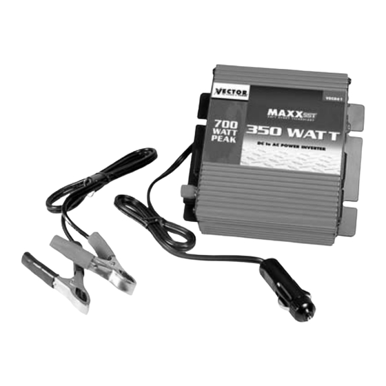
VEC061
350 WATT
POWER INVERTER
NEW
SOFT START
TECHNOLOGY
700 WATT
PEAK
OWNER'S MANUAL
& WARRANTY INFORMATION
THIS MANUAL CONTAINS IMPORTANT INFORMATION REGARDING
SAFETY, OPERATION, MAINTENANCE AND STORAGE OF THIS PRODUCT.
BEFORE USE, READ AND UNDERSTAND ALL CAUTIONS, WARNINGS,
INSTRUCTIONS AND PRODUCT LABELS, PLUS YOUR VEHICLE'S BATTERY
MANUFACTURER GUIDELINES. FAILURE TO DO SO COULD RESULT IN
.
INJURY AND/OR PROPERTY DAMAGE
4140 SW 28TH WAY, FT. LAUDERDALE, FL 33312
TEL 954-584-4446 • FAX 954-584-5556
www.vectormfg.com
Advertisement
Table of Contents

Related Manuals for Vector VEC061


Summary of Contents for Vector VEC061
-
Page 1: Warranty Information
VEC061 350 WATT POWER INVERTER SOFT START TECHNOLOGY 700 WATT PEAK OWNER’S MANUAL & WARRANTY INFORMATION THIS MANUAL CONTAINS IMPORTANT INFORMATION REGARDING SAFETY, OPERATION, MAINTENANCE AND STORAGE OF THIS PRODUCT. BEFORE USE, READ AND UNDERSTAND ALL CAUTIONS, WARNINGS, INSTRUCTIONS AND PRODUCT LABELS, PLUS YOUR VEHICLE’S BATTERY MANUFACTURER GUIDELINES. - Page 2 IMPORTANT SAFETY INSTRUCTIONS To ensure reliable service, your power inverter must be installed and used properly. Please read the installation and operating instructions thoroughly prior to installation and use. Pay particular attention to the WARNING and CAUTION statements in this manual. The CAUTION statements advise against certain conditions and practices that may result in damage to your inverter.
-
Page 3: Table Of Contents
CONTENTS 1. INTRODUCTION ............4 2. CONTROLS, INDICATORS AND CONNECTORS ....4,5 3. HOW YOUR INVERTER WORKS ..........5 3.1 Principal of Operation ............5 3.2 The Maxx 350SST Output Waveform ........6 4. INSTALLATION..............6 4.1 Power Source Requirements ..........6,7 4.2 Connection to Power Source..........7,8 4.3 Connection to Load ............8,9 4.4 Placement of Inverter ............9 5. -
Page 4: Introduction
INTRODUCTION Your new Vector MAXX350SST inverter is one in a series of the most advanced DC to AC inverters available today. With proper care and appropriate usage, it will give you years of dependable service in your car, truck, RV or boat. -
Page 5: How Your Vector Inverter Works
1. HIGH SPEED COOLING FAN 2. (+) DC POWER CONNECTIONS 3. (–) DC POWER CONNECTIONS HOW YOUR VECTOR INVERTER WORKS The inverter converts low voltage DC (direct current) from a battery or other power source to standard 110 volt AC (alternating current) household power. -
Page 6: The Maxx 350Sst Output Waveform
3.2 THE MAXX 350SST OUTPUT WAVEFORM The AC output waveform of the MAXX350SST is known as “modified sine wave”. It is a waveform that has characteristics similar to the sine wave shape of utility power. This type of waveform is suitable for most AC loads, including linear and switching power supplies used in electronic equipment, transformers, and motors. -
Page 7: Connection To Power Source
CAUTION: The MAXX 350SST must be connected only to batteries with a nominal output voltage of 12 volts. The unit will not operate from a 6 volt battery and will sustain permanent damage if connected to a 24 volt battery. CONNECTION TO POWER SOURCE The MAXX350SST comes equipped with a cigarette lighter plug and battery clip cables for connection to the power source:... -
Page 8: Connection To Load
Check to be sure that all connections between battery clips and terminals are secure. Direct Hardwiring to Power Source: Use #10 AWG wire if the inverter to power source connection is 14 feet or less. For longer cable lengths use #8 AWG wire. In either case, protect the positive (+) wire from shorts by installing a 50 Amp fuse or circuit breaker close to the DC power source (battery) terminal. -
Page 9: Placement Of Inverter
into the AC receptacle(s). The green LED indicator lights to indicate that the inverter is functioning. Make sure the combined load requirement of your equipment does not exceed 350SST watts. The MAXX350SST is engineered to be connected directly to standard electrical and electronic equipment in the manner described above. -
Page 10: Operating Tips
With a typical vehicle battery, a minimum operating time of 2 to 3 hours can be expected. In most instances, 5 to 10 hours of operating time is achievable. However, Vector recommends that the operator start the vehicle every 2 to 3 hours to recharge the battery system. This will guard against any unexpected shut-down of the equipment and will ensure that there is always sufficient battery capacity to start the vehicle’s engine. -
Page 11: Protective Features Of Inverter
The inverter draws less than 0.3 ampere from the battery when it is not supplying power to a load. In most instances, the inverter can be left connected to the battery when not in use since it draws so little current. However, if the vehicle is to remain unused for several days, disconnect the inverter from the battery. -
Page 12: Common Problems
Television Interference: The Vector MAXX350SST is shielded to minimize interference with TV signals. However, in some instances, some interference may still be visible, particularly with weak TV signals. Try the following corrective measures: •... -
Page 13: Troubleshooting
TROUBLESHOOTING GUIDE: TABLE 1 - INVERTER POWER SWITCH TURNED ON TROUBLE/ INDICATION POSSIBLE CAUSE SUGGESTED REMEDY No AC output – DC input below 10 Volts Recharge or replace red LED lit battery No AC output – Excessive appliance Reduce load-wait for red LED lit load-thermal shutdown inverter to cool. -
Page 14: Fuse Replacement
If the unit is damaged during fuse replacement, the warranty may be voided. Vector recommends contacting Vector Technical Support for guidance. Based on experience, it is best to return the unit to Vector for repair. Vector Technical Support can be reached by calling 954-584-4446, extension 19 or toll-free 866 584- 5504. - Page 15 If the unit is repaired, new or reconditioned replacement parts may be used, at Vector Manufacturing’s option. A unit may be replaced with a new or reconditioned unit of the same or comparable design. The repaired or replaced unit will then be warranted under the terms of the remainder of the warranty period.
- Page 16 Vector Manufacturing. If activating Additional Extended Two Year Warranty, (total two years) enclose check or money order for $20.00 Enter “VEC061” as Model and Power Inverter as “Product Type”. All Vector © 2004 VECTOR MANUFACTURING, Ltd. FT. LAUDERDALE, FL 33312...
Need help?
Do you have a question about the VEC061 and is the answer not in the manual?
Questions and answers