Husqvarna 326LS Owner's Manual
Owners manual
Hide thumbs
Also See for 326LS:
- Operator's manual (60 pages) ,
- Workshop manual (72 pages) ,
- Operator's manual (40 pages)
Table of Contents

Related Manuals for Husqvarna 326LS


Summary of Contents for Husqvarna 326LS
- Page 1 Oper ator’s manual (EPA) 326C 326L 326LS 326L 326LD X-series X-series Please r ead the operator’s manual carefully and make sure you E E E E n n n n g g g g l l l l i i i i s s s s h h h h...
-
Page 2: Key To Symbols
KEY TO SYMBOLS Symbols WARNING! Clearing saws, brushcutters and trimmers can be dangerous! Careless Only intended for trimmer heads. or incorrect use can result in serious or fatal injury to the operator or others. It is extremely important that you read and understand the contents of the operator’s manual. -
Page 3: Table Of Contents
CONTENTS Contents Note the following before starting: KEY TO SYMBOLS Please read the operator’s manual carefully. Symbols ............... Maintenance, replacement, or repair of the emission control CONTENTS devices and system may be performed by any nonroad Contents ..............engine repair establishment or individual. Note the following before starting: ........ -
Page 4: Introduction
Dear customer! Congratulations on your choice to buy a Husqvarna product! Husqvarna is based on a tradition that dates back to 1689, when the Swedish King Karl XI ordered the construction of a factory on the banks of the Huskvarna River, for production of muskets. The location was logical, since water power was harnessed from the Huskvarna River to create the water-powered plant. -
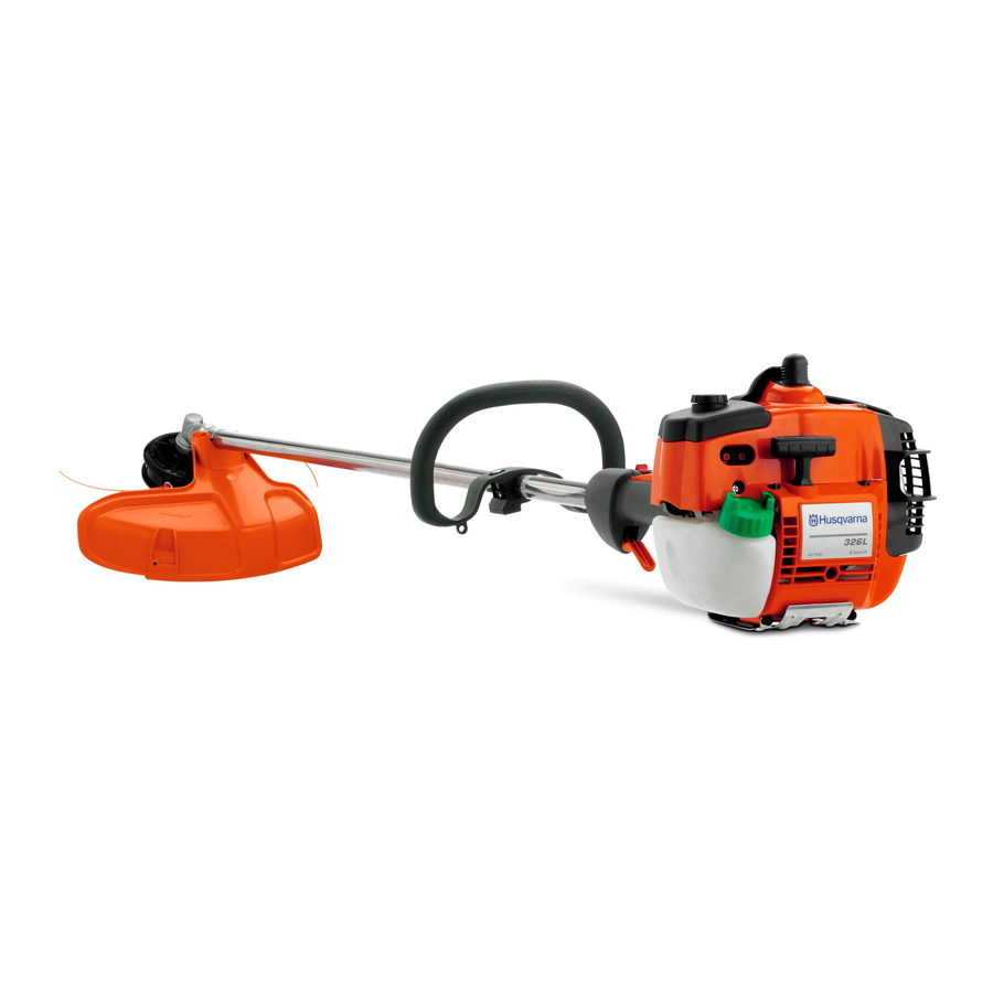
Page 5: What Is What
WHAT IS WHAT? What is what? 1 Trimmer head 13 Choke control 2 Grease filler cap, bevel gear 14 Air purge 3 Bevel gear 15 Air filter cover 4 Cutting attachment guard 16 Handle adjustment 5 Shaft 17 Shaft coupling 6 Loop handle 18 Operator’s manual 7 Throttle control... -
Page 6: General Safety Precautions
GENERAL SAFETY PRECAUTIONS Important Personal protective equipment IMPORTANT! IMPORTANT! The machine is only designed for trimming grass. A clearing saw, brushcutter or trimmer can be dangerous if used incorrectly or carelessly, and can cause serious or The only accessories you can operate with this engine unit fatal injury to the operator or others. -
Page 7: Machine's Safety Equipment
GENERAL SAFETY PRECAUTIONS CLOTHING Make sure the throttle control is locked at the idle setting when the throttle lockout is released. Wear clothes made of a strong fabric and avoid loose clothing that can catch on twigs and branches. Always wear heavy, long pants. - Page 8 GENERAL SAFETY PRECAUTIONS Cutting attachment guard Regularly check the vibration damping units for cracks or deformation. Check that the vibration damping element is undamaged and securely attached. WARNING! Overexposure to vibration can This guard is intended to prevent loose objects from being lead to circulatory damage or nerve damage thrown towards the operator.
-
Page 9: Cutting Equipment
GENERAL SAFETY PRECAUTIONS Cutting equipment If the muffler on your machine is fitted with a spark arrestor screen this must be cleaned regularly. A blocked screen will cause the engine to overheat and may lead to serious This section describes how to choose and maintain your damage. -
Page 10: Assembly
• Slide the spacer into the slot in the loop handle. • 326L/326LS: Fit the nut, washer and screw. Fitting the trimmer head 326LX/326LDX: Fit the nut, knob and screw. Do not overtighten. •... -
Page 11: Fitting A Trimmer Guard And Superauto Ii 1" Trimmer Head
Fitting a trimmer guard and Fitting other guards and cutting Superauto II 1" trimmer head attachments (326L, 326LS, 326Lx, 326LDx) (326L, 326LS, 326Lx, 326LDx) • Fit the correct trimmer guard (A) for use with the trimmer head. Hook the trimmer guard/combination guard onto the fitting on the shaft and secure with the bolt (L). -
Page 12: Fuel Handling
• In order to prevent unintentional starting of the engine, the • For best results and performance use HUSQVARNA two- spark plug cap must always be removed during long-term stroke engine oil, which is specially formulated for our air- storage, if the machine is not under close supervision and cooled two stroke-engines. -
Page 13: Fueling
FUEL HANDLING Mixing Fueling • Always mix the gasoline and oil in a clean container intended for fuel. • Always start by filling half the amount of the gasoline to be used. Then add the entire amount of oil. Mix (shake) the fuel mixture. -
Page 14: Starting And Stopping
STARTING AND STOPPING Check before starting Starting and stopping • Check the blade to ensure that no cracks have formed at the bottom of the teeth or by the centre hole. The most WARNING! The complete clutch cover and common reason why cracks are formed is that sharp shaft must be fitted before the machine is corners have been formed at the bottom of the teeth while started, otherwise the clutch can come loose... - Page 15 STARTING AND STOPPING CAUTION! Do not pull the starter cord all the way out and do not let go of the starter handle when the cord is fully extended. This can damage the machine. CAUTION! Do not put any part of your body in marked area. Contact can result in burns to the skin, or electrical shock if the spark plug cap has been damaged.
-
Page 16: Working Techniques
WORKING TECHNIQUES General working instructions 6 Always hold the machine with both hands. Hold the machine on the right side of your body. IMPORTANT! This section takes up the basic safety precautions for working with a trimmer. If you encounter a situation where you are uncertain how to proceed you should ask an expert. -
Page 17: Grass Trimming With Trimmer Head
WORKING TECHNIQUES Grass trimming with a trimmer head Sweeping • The fan effect of the rotating cord can be used for quick and easy clearing up. Hold the cord parallel to and above the area to be swept and move the tool to and fro. Trimming •... -
Page 18: Maintenance
Basic setting • The basic carburetor settings are adjusted during testing Your Husqvarna product has been designed and at the factory. The basic setting is richer than the optimal manufactured to specifications that reduce harmful setting and should be maintained for the first few hours the emissions. -
Page 19: Muffler
MAINTENANCE Fine adjustment of the idle speed T Correctly adjusted carburetor Adjust the idle speed using the idle adjustment screw T, if it is When the carburetor is correctly adjusted the machine will necessary to readjust. First turn the idle adjustment screw T accelerate without hesitation and burble a little at maximum clockwise until the cutting attachment starts to rotate. -
Page 20: Cooling System
MAINTENANCE Cooling system Two-piece shaft (326LDx) To keep the working temperature as low as possible the machine is equipped with a cooling system. The drive shaft end in the lower shaft should be lubricated with grease every 30 hours. There is a risk that the drive shaft ends (splined coupling) on models with two-piece shafts will seize if they are not lubricated regularly. -
Page 21: Bevel Gear
MAINTENANCE Oiling the air filter Always use HUSQVARNA filter oil, art. no. 531 00 92-48. The filter oil contains a solvent to make it spread evenly through the filter. You should therefore avoid skin contact. Put the filter in a plastic bag and pour the filter oil over it. -
Page 22: Maintenance Schedule
MAINTENANCE Maintenance schedule The following is a list of the maintenance that must be performed on the machine. Most of the items are described in the Maintenance section. Daily Weekly Monthly Maintenance maintenance maintenance maintenance Clean the outside of the machine. Make sure the throttle trigger lock and the throttle function correctly from a safety point of view. -
Page 23: Technical Data
TECHNICAL DATA Technical data 326C 326L/326LS 326Lx 326LDx Engine Cylinder displacement, cu.in/cm 1,50/24,5 1,50/24,5 1,50/24,5 1,50/24,5 Cylinder bore, inch/mm 1,34/34,0 1,34/34,0 1,34/34,0 1,34/34,0 Stroke, inch/mm 1,06/27 1,06/27 1,06/27 1,06/27 Idle speed, rpm 2700 2700 2700 2700 Recommended max. fast idle speed, rpm... - Page 24 537 18 33-12 The accessories have been developed mainly for the Husqvarna 125LD trimmer, but can also be used in combination with the specified power heads and have been evaluated to applicable ISO- and EN safety requirement standards by the Swedish Machinery Testing Institute.
-
Page 25: Federal And California Emissions Control Warranty Statement
Husqvarna Forest & Garden at no cost. Any such part fuel tank, filters and other associated components. Also, repaired or replaced under warranty is warranted for the included may be hoses, belts, connectors, sensors, and other remainder of the period prior to the first scheduled... -
Page 26: Where To Get Warranty Service
HOW TO FILE A CLAIM If you have any questions regarding your warranty rights and responsibilities, you should contact your nearest authorized servicing dealer or call Husqvarna Forest & Garden at 1-800- 487-5963. WHERE TO GET WARRANTY SERVICE Warranty services or repairs are provided through all Husqvarna Forest &... - Page 27 Trimmy Hit Junior 5,75 m 15 cm 6" ~ 2,8 m 15 cm 6" 15 cm “Click” 6"...
- Page 28 Trimmy VII 7,0 m 23" 12 cm 5" ~ 3,5 m 11" ~ 15 cm 6" 15 cm 6"...
- Page 29 6,0 m 10 cm 4" 3,05 m "Clic" 15 cm 6"...
- Page 30 T25C 2,75 m 2,75 m 15 cm 6"...
- Page 31 T25C 2,75 m x 2 9' x 2 2,75 m 2,75 m "Clic" 15 cm 6"...
- Page 32 Trimmy H II 15 cm 6" 7,5 m ~ 3,7 m 15 cm 6"...
- Page 33 Trimmy Hit “Click” 7,0 m 12 cm 5" ~ 3,5 m “Click” ~ 15 cm " 15 cm 6 "...
- Page 34 Trimmy Hit Pro 7,5 m 15 cm 6" ~ 3,7 m 15 cm 6" 15 cm “Click” 6"...
- Page 35 Super Auto II Super Auto II 1 " 4,0 m 15 cm ~2,0 m 6 " 6,5 ' 15 cm 6 "...
- Page 36 8,5 m 10 cm 4" 4,2 m "Clic" 15 cm 6"...
- Page 37 4,25 m 4,25 m 15 cm 6" 15 cm 6"...
- Page 38 ´®z+R:G¶5ߨ ´®z+R:G¶5ߨ...
- Page 39 T35, T35x 8,5 m 10 cm 4" 4,3 m "Clic" 15 cm 6"...
- Page 40 1150263-95 ´®z+R:G¶5ߨ ´®z+R:G¶5ߨ 2007-01-30...
Need help?
Do you have a question about the 326LS and is the answer not in the manual?
Questions and answers