Advertisement
INSTRUCTION MANUAL
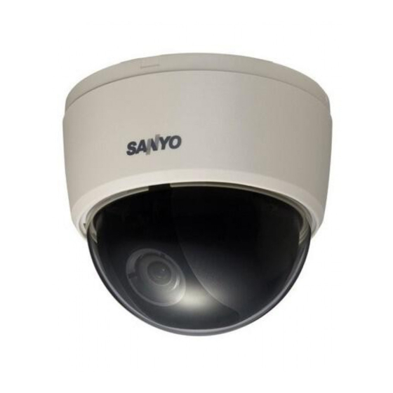
Color CCD Camera
THIS INSTALLATION SHOULD BE MADE BY A QUALIFIED SERVICE
PERSON AND SHOULD CONFIRM TO ALL LOCAL CODES.
Please read this instruction manual carefully in order to ensure correct
installation.
This manual covers 2 models. Any difference between the 2 models is
indicated when necessary.
CONTENTS
PRECAUTION ............................................................................. 2
NOTES OF USE ........................................................................... 5
INSTALLATION ........................................................................... 8
CCD CHARACTERISTIC ............................................................... 10
SPECIFICATION ......................................................................... 11
VCC-9784VA
VCC-9785VP
Advertisement

Subscribe to Our Youtube Channel
Summary of Contents for Sanyo VCC-9784VA
-
Page 1: Table Of Contents
INSTRUCTION MANUAL VCC-9784VA VCC-9785VP Color CCD Camera THIS INSTALLATION SHOULD BE MADE BY A QUALIFIED SERVICE PERSON AND SHOULD CONFIRM TO ALL LOCAL CODES. Please read this instruction manual carefully in order to ensure correct installation. This manual covers 2 models. Any difference between the 2 models is indicated when necessary. -
Page 2: Precaution
PRECAUTION CAUTION: Safety Guard Changes or modifications not expressly approved by the manufacturer may void the user’s authority to operate this equipment. This equipment has been tested and found to comply with the limits for a Class CAUTION: TO REDUCE THE RISK OF B digital device, pursuant to Part 15 of the ELECTRIC SHOCK, DO NOT REMOVE FCC Rules. - Page 3 For EU Users Please note: Your SANYO product is designed and manufactured with high quality materials and componets which can be recycled and reused. This symbol means that electrical and electronic equipment, at their end- of-life, should be disposed of separately from your household waste.
-
Page 4: Power Supply
NOTES OF USE ■ Power supply This dome camera can operate on AC24V or DC12V. The camera automatically transfers the power. When connecting DC12V power source, check polarity before switching on as a precaution. Wrong connection may cause malfunction and/or damage to the video camera. -
Page 5: Notes Of Use
NOTES OF USE ■ CONNECTION Fig-1 (a) Video out connector (b) Power connector (DC12V/AC24V) ■ LOCATION AND FUNCTION OF PARTS (1) Conduit holes (sealed): Connect the wires through the hole. The conduit holes are on the side of the unit casing. The access hole is sealed at the fac tory. - Page 6 (7) V Phase adjustment Pot (PAL model only): Adjust the phase difference between this camera and other cameras when in line lock mode. Note: Line lock fuction won’t be active on VCC-9784VA. (8) Mode setting DIP switch: The following DIP switches are set to default position (shaded) as shipped from factory.
- Page 7 NOTES OF USE 3: DC/AES Mode switch •DC : Suitable to DC lens. •AES: Suitable to AES lens. 4: LL switch (VCC-9785VP only) Use this switch to set the camera synchronization mode internal or line lock. When the camera power is using DC12V power input, the camera is in the internal operation mode regardless of the switch setting.(lnitial setting:LL) (9) Monitor out:...
-
Page 8: Installation
INSTALLATION Fig-3 1. Stick the guide pattern on the wall/ceiling (See Fig-3 on page 6). 2. Drill two holes according the guide pattern then plug anchor hold driver into the holes. 3. lnstall the camera through these holes onto the wall with the pro- vided screws (TP4*15) - Page 9 INSTALLATION ■ ADJUSTMENT Fig-4 (1) Lock ring (2) Zoom lever (3) Focus lever (4) Tilt-adj screw (5) Axis ring Adjusting procedures: 1. Hold the lens so that it does not rotate. Loosen the lock ring (1) and Tilt-adj screw (4). Make sure to hold the lens when you turn the lock ring, otherwise the lens may rotate with the lock ring and the cable may become twisted.
-
Page 10: Ccd Characteristic
INSTALLATION ■ ATTACH THE DOME COVER (1) DOME BODY (2) INNER LINER (3) DOME COVER Fig-5 1. Match the screws on the unit casing casing to the screw holes (3 locations) on the unit casing 2. Fix the inner liner into the pan-adj screw. 3. -
Page 11: Specification
SPECIFICATION Fig-6... - Page 12 SPECIFICATION VCC-9785VP VCC-9784VA PAL standard 625 lines NTSC standard 525 lines Scanning system 50fields/sec. 60fields/sec. Image sensor 1/3" Interlace CCD sensor Number of effective pixels 752(H) x 582(V) 768(H) x 494(V) Horizontal resolution 540 TV lines (Typical) Lens Buit-in varifocal lens, f=2.8 to 10 mm (F1.3) Panning range ±180°...
- Page 13 Sanyo Electric Co., Ltd. Printed in Taiwan...


Need help?
Do you have a question about the VCC-9784VA and is the answer not in the manual?
Questions and answers