Weider 8700 I User Manual
English manual
Hide thumbs
Also See for 8700 I:
- Gebruiksaanwijzing (32 pages) ,
- Manuel de l'utilisateur (32 pages) ,
- Bedienungsanleitung (32 pages)
Table of Contents
Advertisement
Model No. WEEVSY30810.2
Serial No.
Write the serial number in the space
above for reference.
Serial Number Decal
(under the seat)
QUESTIONS?
If you have questions, or if there are
missing parts, please contact us:
UNITED KINGDOM
Call: 08457 089 009
From Ireland: 053 92 36102
Website: www.iconsupport.eu
E-mail: csuk@iconeurope.com
Write:
ICON Health & Fitness, Ltd.
c/o HI Group PLC
Express Way
CASTLEFORD
WF10 5QJ
UNITED KINGDOM
AUSTRALIA
Call: 1800 993 770
E-mail: australiacc@iconfitness.com
Write:
ICON Health & Fitness
PO Box 635
WINSTON HILLS NSW 2153
AUSTRALIA
CAUTION
Read all precautions and instruc-
tions in this manual before using
this equipment. Keep this manual
for future reference.
USER'S MANUAL
www.iconeurope.com
Advertisement
Table of Contents

Subscribe to Our Youtube Channel
Related Manuals for Weider 8700 I


Summary of Contents for Weider 8700 I
- Page 1 Model No. WEEVSY30810.2 Serial No. USER’S MANUAL Write the serial number in the space above for reference. Serial Number Decal (under the seat) QUESTIONS? If you have questions, or if there are missing parts, please contact us: UNITED KINGDOM Call: 08457 089 009 From Ireland: 053 92 36102 Website: www.iconsupport.eu E-mail: csuk@iconeurope.com...
-
Page 2: Table Of Contents
If a decal is missing or illegible, see the front cover of this manual and request a free replacement decal. Apply the decal in the location shown. Note: The decal(s) may not be shown at actual size. WEIDER is a registered trademark of ICON IP, Inc. -
Page 3: Important Precautions
IMPORTANT PRECAUTIONS WARNING: To reduce the risk of serious injury, read all important precautions and instructions in this manual and all warnings on your weight system before using your weight system. ICON assumes no responsibility for personal injury or property damage sustained by or through the use of this product. -
Page 4: Before You Begin
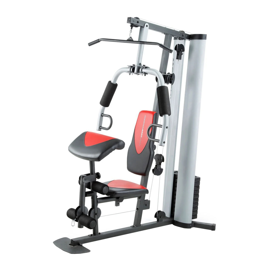
BEFORE YOU BEGIN Thank you for selecting the versatile WEIDER 8700 reading this manual, please see the front cover of this ® I weight system. The weight system offers a selection manual. To help us assist you, note the product model of weight stations designed to develop every major number and serial number before contacting us. -
Page 5: Part Identification Chart
PART IDENTIFICATION CHART Use the drawings below to identify the small parts needed for assembly. The number in parentheses below each drawing is the key number of the part, from the PART LIST near the end of this manual. The number following the key number is the quantity needed for assembly. -
Page 6: Assembly
ASSEMBLY • Assembly requires two persons. • In addition to the included tool(s), assembly requires the following tools: • Because of its weight and size, assemble the one Phillips screwdriver weight system in the location where it will be used. Make sure that there is enough clearance one standard screwdriver to walk around the weight system. - Page 7 Frame Assembly To make assembly easier, read the information on page 6 before you begin. Attach the Foot Plate (38) to the Base (1) with an M10 x 130mm Bolt (72) and an M10 Locknut (56). Do not overtighten the Locknut; the Foot Plate must pivot easily.
- Page 8 3. Attach the Upright (3) to the Base (1) with two M8 x 63mm Carriage Bolts (87) and two M8 Locknuts (58). Do not tighten the Locknuts yet. 4. Attach the Front Leg (7) to the Base (1) with two M8 x 63mm Carriage Bolts (87) and two M8 Locknuts (58).
- Page 9 5. Attach the Seat Tube (6) to the Upright (3) with two M8 x 65mm Bolts (68), two M8 Washers (59), and two M8 Locknuts (58). Do not tighten the Locknuts yet. Attach the Seat Tube (6) to the Front Leg (7) in the same way.
- Page 10 7. Attach the Top Frame (4) to the Upright (3) with two M10 x 67mm Bolts (71), two M10 Washers (57), and two M10 Locknuts (56). Do not tighten the Locknuts yet. Attach the Top Frame (4) to the Weight Guides (21) with two M10 x 25mm Screws (74).
- Page 11 10. Apply grease to an M10 x 77mm Bolt (79). Attach the Pivot Frame (5) to the Top Frame (4) with the M10 x 77mm Bolt (79) and an M10 Locknut (56). Do not overtighten the Locknut; the Pivot Frame must pivot easily. Grease Arm Assembly 11.
-
Page 12: Shoulder
13. Apply grease to an M10 x 86mm Carriage Bolt (67) and to two Arm Bushings (44). Attach the Left Arm (10) to the Pivot Frame (5) with the M10 x 86mm Carriage Bolt (67), a Carriage Bolt Bushing (20), the two Arm Bushings (44), an M10 Washer (57), and an M10 Locknut (56). -
Page 13: Large
15. Identify the two V-pulleys (46), the nine Thick Pulleys (not shown), and the two Thin Pulleys (not shown). Route the Arm Cable (54) over a V-pulley (46). Attach the V-pulley (46), a Large Cable Trap (50), two Full Guards (41), and an M10 Washer (57) to the Upright (3) with an M10 x 63mm Bolt 57 46 50 (75) and an M10 Locknut (56). - Page 14 18. Apply grease to an M8 x 22mm Shoulder Bolt (65). Attach the Arm Cable (54) to the right Cable Grease Pivot (39) with the M8 x 22mm Shoulder Bolt 54 39 (65) and an M8 Locknut (58). 19. Identify the Low Cable (53). Route the Low Cable through the Leg Lever (8) and the Front Leg (7).
- Page 15 21. Route the Low Cable (53) through the Upright (3) and under a Thick Pulley (48). Attach the Thick Pulley (48) inside the Upright (3) with an M10 x 46mm Bolt (81) and an M10 Locknut (56). 22. Route the Low Cable (53) over a Thick Pulley (48).
- Page 16 24. Attach the Low Cable (53) to the U-bracket (45) with an M8 Washer (59) and an M8 Locknut (58). See the inset drawing. Do not overtighten the M8 Locknut (58); it should be threaded onto the end of the Low Cable (53) so that only two threads are showing above the Locknut.
- Page 17 27. Wrap the High Cable (55) under a Thick Pulley (48). Attach the Thick Pulley (48), a Small Cable Trap (51), and two Half Guards (43) to the upper hole in the U-bracket (45) with an M10 x 51mm Bolt (66) and an M10 Locknut (56).
- Page 18 30. Thread an M12 Nut (84) all the way onto the High Cable (55). Place a Large Washer (85) on top of the Weight Selector (24). Tighten the High Cable (55) into the Weight Selector (24) until all the slack is removed from the cables.
-
Page 19: M4.2 X 16Mm Self-Tapping
33. Insert the Pad Tube (29) into the Front Leg (7). Slide a Small Foam Pad (28) onto each side of the Pad Tube (29). Then, press a Pad Cap (34) into each Small Foam Pad. Slide a Small Foam Pad (28) onto each end of the Leg Lever (8). - Page 20 35. Attach a Shroud Support (19) and the bottom of the Left Shroud (17) to the Base (1) and the Stabilizer (2) with four M4.2 x 16mm Self-tapping Screws (49) and four M4 Washers (33). Do not tighten the Screws yet. Repeat steps 34 and 35 to attach the Right Shroud (not shown).
-
Page 21: Adjustment
ADJUSTMENT This section explains how to adjust the weight system. See the EXERCISE GUIDELINES on page 26 for impor- tant information about how to get the most benefit from your exercise program. Also, refer to the accompanying exercise guide to see the correct form for several exercises. Make sure that all parts are properly tightened each time the weight system is used. - Page 22 CONVERTING THE ARMS To use the Arms (9, 10) as butterfly arms, insert the Arm Pins (40) into the holes in the Upright (3) as shown. To use the Arms (9, 10) as press arms, insert the Arm Pins (40) into the holes in the Pivot Frame (5) and the Arms.
-
Page 23: Weight Resistance Chart
LOCKING THE WEIGHT STACK To lock the weight stack after each workout, insert the Lock Pin (89) through one of the Weight Guides (21), and secure the Lock (88) on the Lock Pin. WEIGHT RESISTANCE CHART The chart below shows the approximate weight resistance at each exercise station. The numbers in the left col- umn refer to the 12.5-lb. -
Page 24: Cable Diagram
CABLE DIAGRAM The drawings below shows the proper routing of the cables. The numbers in each drawing show the proper route of that cable. Use the drawings to make sure that the cables, cable traps, and guards are assembled correctly. If the cables are not assembled correctly, the weight system will not function properly and damage may occur. -
Page 25: Maintenance
MAINTENANCE Make sure that all parts are properly tightened each time the weight system is used. Replace any worn parts immediately. To clean the weight system, use a damp cloth and a mild, non-abrasive detergent; do not use sol- vents to clean the weight system. TIGHTENING THE CABLES Woven cable, the type of cable used on the weight system, can stretch slightly when it is first used. -
Page 26: Exercise Guidelines
EXERCISE GUIDELINES FOUR TYPES OF STRENGTH WORKOUTS workout, and the numbers of repetitions and sets to complete. Progress at your own pace and be sensitive Note: A “repetition” is one complete cycle of an to your body’s signals. Follow each workout with at exercise, such as one sit-up. - Page 27 EXERCISE LOG Make copies of this page, and use the copies to schedule and record your strength and aerobic workouts. Scheduling and recording your workouts will help you to make exercise a regular and enjoyable part of your life. Strength Exercise Lbs.
- Page 28 NOTES...
-
Page 29: M8 X 63Mm Carriage
PART LIST Model No. WEEVSY30810.2 R0912A Key No. Qty. Description Key No. Qty. Description Base Small Cable Trap Stabilizer 13mm Spacer Upright Low Cable Top Frame Arm Cable Pivot Frame High Cable Seat Tube M10 Locknut Front Leg M10 Washer Leg Lever M8 Locknut Right Arm... -
Page 30: Exploded Drawing
EXPLODED DRAWING A Model No. WEEVSY30810.2 R0912A 65 54... - Page 31 EXPLODED DRAWING B Model No. WEEVSY30810.2 R0912A 50 41...
-
Page 32: Ordering Replacement Parts
ORDERING REPLACEMENT PARTS To order replacement parts, please see the front cover of this manual. To help us assist you, be prepared to provide the following information when contacting us: • the model number and serial number of the product (see the front cover of this manual) •...
Need help?
Do you have a question about the 8700 I and is the answer not in the manual?
Questions and answers
Two questions: 1. Why does the weight chart for the 8700I show uneven weight progression as you go up in the number of weight plates? Surely the gaps should be equal? 2. 4 plates weigh 50lbs but the 116lbs indicated for Arm Press for 4 platea is due to the adverse leverage presumably?