Advertisement
Table of Contents
- 1 Table of Contents
- 2 Warning Decal Placement
- 3 Important Precautions
- 4 Before You Begin
- 5 Part Identification Chart
- 6 Assembly
- 7 How to Use the Exercise Bike
- 8 To Adjust the Reed Switch
- 9 Maintenance and Troubleshooting
- 10 Exercise Guidelines
- 11 Part List
- 12 Exploded Drawing
- 13 Ordering Replacement Parts
- 14 Recycling Information
- Download this manual
Model No. NTEVEX74013.0
Serial No.
USER'S MANUAL
Write the serial number in the space
above for reference.
Serial Number Decal
(under frame)
CUSTOMER SERVICE
UNITED KINGDOM
Call: 08457 089 009
From Ireland: 053 92 36102
Website: www.iconsupport.eu
E-mail: csuk@iconeurope.com
Write:
ICON Health & Fitness, Ltd.
c/o HI Group PLC
Express Way
CASTLEFORD
WF10 5QJ
UNITED KINGDOM
AUSTRALIA
Call: 1800 993 770
E-mail: australiacc@iconfitness.com
Write:
ICON Health & Fitness
PO Box 635
WINSTON HILLS NSW 2153
AUSTRALIA
CAUTION
Read all precautions and instruc-
tions in this manual before using
this equipment. Keep this manual
www.iconeurope.com
for future reference.
Advertisement
Table of Contents

Related Manuals for NordicTrack Ex 3.2 Bike


Summary of Contents for NordicTrack Ex 3.2 Bike
- Page 1 Model No. NTEVEX74013.0 Serial No. USER’S MANUAL Write the serial number in the space above for reference. Serial Number Decal (under frame) CUSTOMER SERVICE UNITED KINGDOM Call: 08457 089 009 From Ireland: 053 92 36102 Website: www.iconsupport.eu E-mail: csuk@iconeurope.com Write: ICON Health &...
-
Page 2: Table Of Contents
If a decal is missing or illegible, see the front cover of this manual and request a free replacement decal. Apply the decal in the location shown. Note: The decal(s) may not be shown at actual size. NORDICTRACK is a registered trademark of ICON IP, Inc. -
Page 3: Important Precautions
IMPORTANT PRECAUTIONS WARNING: To reduce the risk of serious injury, read all important precautions and instructions in this manual and all warnings on your exercise bike before using your exercise bike. ICON assumes no responsibility for personal injury or property damage sustained by or through the use of this product. -
Page 4: Before You Begin
BEFORE YOU BEGIN Thank you for selecting the revolutionary reading this manual, please see the front cover of this NORDICTRACK EX 3.2 exercise bike. Cycling is an manual. To help us assist you, note the product model ® effective exercise for increasing cardiovascular fitness, number and serial number before contacting us. -
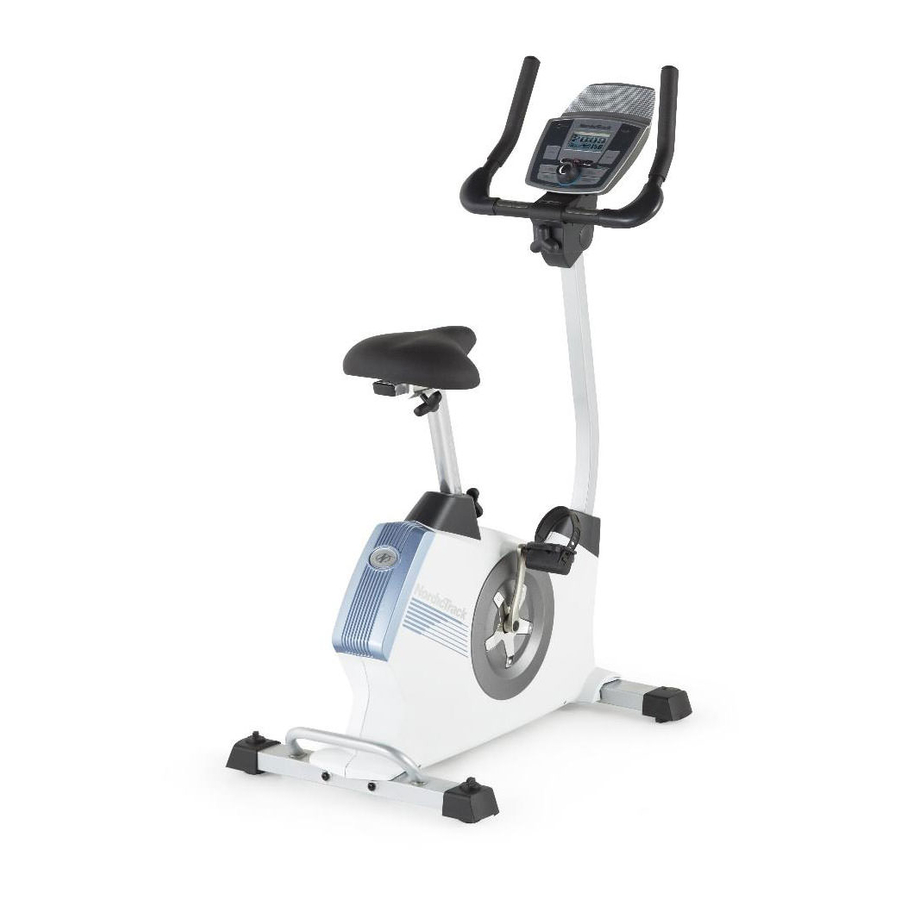
Page 5: Part Identification Chart
PART IDENTIFICATION CHART Use the drawings below to identify the small parts needed for assembly. The number in parentheses below each drawing is the key number of the part, from the PART LIST near the end of this manual. The number following the key number is the quantity needed for assembly. -
Page 6: Assembly
ASSEMBLY • Assembly requires two persons. • In addition to the included tool(s), assembly requires the following tools: • Place all parts in a cleared area and remove the one Phillips screwdriver packing materials. Do not dispose of the packing materials until you finish all assembly steps. - Page 7 2. Set a sturdy piece of packing material under the rear of the Frame (1). Have a second person hold the Frame to prevent it from tipping while you complete this step. Identify the Rear Stabilizer (3). Note: The Rear Stabilizer does not have wheels;...
- Page 8 4. Loosen the Seat Post Knob (27) in the Frame (1) a few turns. Orient the Seat Post (6) as shown. Then, insert the Seat Post into the Frame (1). Adjustment Holes Slide the Seat Post (6) upward or downward to the desired position, and tighten the Seat Post Knob (27) into an adjustment hole in the Seat Post.
- Page 9 6. Remove the Seat Knob (26) from the Seat Carriage (24). Hold the Seat Bracket (30) inside the Seat Carriage to prevent it from moving. Next, set the Seat Carriage (24) on the Seat Post (6). Insert the Seat Knob (26) upward into the Seat Post, and tighten the Seat Knob into the Seat Bracket (30) inside the Seat Carriage.
- Page 10 8. While a second person holds the Console (13) near the Upright (4), connect the console wires to the Extension Wire (59) and to the Pulse Avoid pinching Wire (61). the wires Insert the excess wire into the Upright (4) or into 61 59 the Console (13).
- Page 11 10. Slide the Front Shield Cover (7) upward onto the Upright (4). While a second person holds the Upright (4) Avoid pinching near the Frame (1), connect the Extension Wire the wires (59) to the Main Wire (58). Insert the Upright (4) into the Frame (1). Tip: Avoid pinching the wires.
- Page 12 12. Plug the Power Adapter (67) into the receptacle on the frame of the exercise bike. If necessary, plug the Power Adapter (67) into the Plug Adapter (A). Note: To plug the Power Adapter (67) into an outlet, see HOW TO PLUG IN THE POWER ADAPTER on page 13.
-
Page 13: How To Use The Exercise Bike
HOW TO USE THE EXERCISE BIKE HOW TO PLUG IN THE POWER ADAPTER To adjust the seat, first loosen the IMPORTANT: If the exercise bike has been exposed seat post knob a to cold temperatures, allow it to warm to room few turns. - Page 14 CONSOLE DIAGRAM FEATURES OF THE CONSOLE you can download personalized workouts, create your own workouts, track your workout results, race against other iFit users, and access many other features. To The advanced console offers an array of features designed to make your workouts more effective and purchase an iFit module at any time, go to enjoyable.
- Page 15 HOW TO USE THE MANUAL MODE Distance (Dist.)—This display mode will show the distance that you have pedaled in miles or 1. Begin pedaling or press any button on the kilometers. console to turn on the console. Pulse—This display mode will show your heart rate When you turn on the console, the display will turn when you use the handgrip heart rate monitor (see on.
- Page 16 Press the Home button to return to the default When your pulse is detected, a heart symbol in the menu (see HOW TO CHANGE CONSOLE calorie display will flash each time your heart beats, SETTINGS on page 20 to set the default menu). one or two dashes will appear, and then your heart rate will be shown.
- Page 17 HOW TO USE AN ONBOARD WORKOUT the profile will begin to flash. If a different resis- tance level and/or target speed is programmed for 1. Begin pedaling or press any button on the the next segment, the resistance level and/or target console to turn on the console.
- Page 18 HOW TO USE A SET-A-GOAL WORKOUT Note: If you manually change the resistance during a calorie goal workout, the length of the workout 1. Begin pedaling or press any button on the will adjust automatically to ensure that you meet console to turn on the console.
- Page 19 HOW TO USE AN IFIT WORKOUT Press the Map button, the Train button, or the Lose Wt. button to download the next workout of that Note: To use an iFit workout, you must have an type in your schedule. optional iFit module. To purchase an iFit module at any time, go to www.iFit.com or call the telephone Press the Compete button to compete in a race number on the front cover of this manual.
- Page 20 6. Follow your progress with the display. HOW TO CHANGE CONSOLE SETTINGS See step 4 on page 15. The console features a user mode that allows you to view usage information, select a unit of measurement, The My Trail tab will show a map of the trail you are and adjust the contrast level of the display.
- Page 21 5. Determine if an iFit module is connected to the 8. Check the status of the iFit module if desired. console. Press the decrease button to view the iFit sta- If an iFit module is connected to the console, the tus display.
-
Page 22: Maintenance And Troubleshooting
MAINTENANCE AND TROUBLESHOOTING Inspect and tighten all parts of the exercise bike regu- Locate the Reed Switch (57). Loosen, but do not larly. Replace any worn parts immediately. remove, the two M4 x 13mm Flange Screws (63). To clean the exercise bike, use a damp cloth and a small amount of mild soap. - Page 23 HOW TO ADJUST THE DRIVE BELT Rotate the right Pedal Disc (17) clockwise to release it from the Right Shield (10). Then, carefully If you can feel the pedals slip while you are pedaling, work the left Pedal Disc off the Right Crank Arm (19). even when the resistance is adjusted to the highest level, the drive belt may need to be adjusted.
-
Page 24: Exercise Guidelines
EXERCISE GUIDELINES Burning Fat—To burn fat effectively, you must exer- WARNING: cise at a low intensity level for a sustained period of Before beginning this time. During the first few minutes of exercise, your or any exercise program, consult your physi- body uses carbohydrate calories for energy. - Page 25 SUGGESTED STRETCHES The correct form for several basic stretches is shown at the right. Move slowly as you stretch; never bounce. 1. Toe Touch Stretch Stand with your knees bent slightly and slowly bend forward from your hips. Allow your back and shoulders to relax as you reach down toward your toes as far as possible.
-
Page 26: Part List
PART LIST Model No. NTEVEX74013.0 R0613A Key No. Qty. Description Key No. Qty. Description Frame Crank Bearing Front Stabilizer Snap Ring Rear Stabilizer Eddy Mechanism Upright M4 x 16mm Screw Handlebar M4 x 19mm Screw Seat Post Idler Front Shield Cover M4 x 13mm Bright Screw Top Shield Cover Resistance Motor... -
Page 27: Exploded Drawing
EXPLODED DRAWING Model No. NTEVEX74013.0 R0613A 57 46... -
Page 28: Ordering Replacement Parts
ORDERING REPLACEMENT PARTS To order replacement parts, please see the front cover of this manual. To help us assist you, be prepared to provide the following information when contacting us: • the model number and serial number of the product (see the front cover of this manual) • the name of the product (see the front cover of this manual) • t he key number and description of the replacement part(s) (see the PART LIST and the EXPLODED DRAWING near the end of this manual) RECYCLING INFORMATION This electronic product must not be disposed of in municipal waste.
Need help?
Do you have a question about the Ex 3.2 Bike and is the answer not in the manual?
Questions and answers