Table of Contents
Advertisement
www.nordictrack.com
Model No. 831.21914.1
Serial No.
USER’'S MANUAL
Write the serial number in the space
above for reference.
Serial Number
Decal
ACTIVATE YOUR
WARRANTY
To register your product and
activate your warranty today, go
to www.nordictrackservice.com/
registration.
CUSTOMER CARE
For service at any time, go to
www.nordictrackservice.com.
Or call 1-800-TO-BE-FIT
(1-800-862-3348)
Mon.––Fri. 6 a.m.––6 p.m. MT
Sat. 8 a.m.––12 p.m. MT
Please do not contact the store.
CAUTION
Read all precautions and instruc-
tions in this manual before using
this equipment. Keep this manual
for future reference.
Advertisement
Table of Contents

Related Manuals for NordicTrack Gx 4.7 Bike


Summary of Contents for NordicTrack Gx 4.7 Bike
- Page 1 Model No. 831.21914.1 Serial No. USER’’S MANUAL Write the serial number in the space above for reference. Serial Number Decal ACTIVATE YOUR WARRANTY To register your product and activate your warranty today, go to www.nordictrackservice.com/ registration. CUSTOMER CARE For service at any time, go to www.nordictrackservice.com.
-
Page 2: Table Of Contents
If a decal is missing or illegible, see the front cover of this manual and request a free replacement decal. Apply the decal in the location shown. Note: The decal(s) may not be shown at actual size. NORDICTRACK is a registered trademark of ICON IP, Inc. -
Page 3: Important Precautions
IMPORTANT PRECAUTIONS WARNING: To reduce the risk of serious injury, read all important precautions and instructions in this manual and all warnings on your exercise bike before using your exercise bike. ICON assumes no responsibility for personal injury or property damage sustained by or through the use of this product. - Page 5 STANDARD SERVICE PLANS...
-
Page 6: Before You Begin
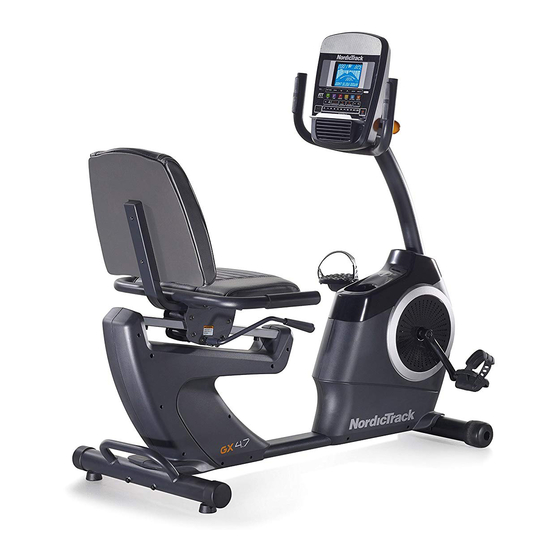
BEFORE YOU BEGIN Thank you for selecting the new NORDICTRACK ® reading this manual, please see the front cover of this GX 4.7 exercise bike. Cycling is an effective exercise manual. To help us assist you, note the product model for increasing cardiovascular fitness, building endur- number and serial number before contacting us. -
Page 7: Part Identification Chart
PART IDENTIFICATION CHART Use the drawings below to identify the small parts needed for assembly. The number in parentheses below each drawing is the key number of the part, from the PART LIST near the end of this manual. The number following the key number is the quantity needed for assembly. -
Page 8: Assembly
ASSEMBLY •• Assembly requires two persons. In addition to the included tool(s), assembly requires the following tools: •• Place all parts in a cleared area and remove the one Phillips screwdriver packing materials. Do not dispose of the packing materials until you nish all assembly steps. one adjustable wrench ••... - Page 9 3. Orient the Front Stabilizer (2) as indicated by the sticker. While a second person lifts the front of the Frame (1), attach the Front Stabilizer (2) to the Frame with two M10 x 80mm Screws (21). 4. Orient the Adjustment Lever (6) as shown. Attach the Adjustment Lever (6) to the Brake Axle (37) with two M6 x 16mm Screws (33), two M6 Split Washers (34), and two M6 Large...
- Page 10 6. Orient the Seat (10) and the Seat Frame (9) as shown. Attach the Seat (10) to the Seat Frame (9) with four M6 x 40mm Screws (27). Start all the Screws, and then tighten them. 7. Attach the Seat Frame (9) to the Seat Carriage (7) with four M8 x 40mm Screws (28).
- Page 11 8. Orient the Backrest (11) as shown. Attach the Backrest (11) to the Backrest Frame (8) with two M6 x 40mm Screws (27). 9. Remove the Accessory Tray (5) from the Left and Right Front Shields (57, 58). Set the Accessory Tray aside.
- Page 12 10. Tip: Avoid pinching the Main Wire (77). Hold the Upright (4) against the Frame (1). Attach the Upright with four M8 x 15mm Screws (24). Start all the Screws, and then tighten them. Avoid Next, orient the Accessory Tray (5) and the pinching Console Cover (16) as shown.
- Page 13 12. While a second person holds the Console (15) near the Handlebar (14), plug the Main Wire (77) and the Pulse Wire (84) into the receptacles on the Console. The connectors on the Main Wire (77) and the Pulse Wire (84) should slide easily into the receptacles and snap into place.
- Page 14 14. Identify the Right Pedal (13). Using an adjustable wrench, firmly tighten the Right Pedal (13) clockwise into the Right Crank Arm (71). Firmly tighten the Left Pedal (not shown) counterclockwise into the Left Crank Arm (not shown). Strap Adjust the right strap to the desired position, and press the ends of the straps onto the tabs on the Right Pedal (13).
-
Page 15: How To Use The Exercise Bike
HOW TO USE THE EXERCISE BIKE HOW TO PLUG IN THE POWER ADAPTER HOW TO ADJUST THE PEDAL STRAPS IMPORTANT: If the To adjust the pedal exercise bike has straps, first pull the been exposed to ends of the straps off Strap cold temperatures, the tabs on the ped-... - Page 16 CONSOLE DIAGRAM MAKE YOUR FITNESS GOALS A REALITY WITH Upload your workout results to the iFit cloud IFIT.COM and track your accomplishments. With your new iFit-compatible fitness equipment, you can use an array of features on iFit.com to make your Set calorie, time, or distance goals for your fitness goals a reality: workouts.
-
Page 17: Features Of The Console
FEATURES OF THE CONSOLE HOW TO USE THE MANUAL MODE The advanced console offers an array of features 1. Begin pedaling or press any button on the designed to make your workouts more effective and console to turn on the console. enjoyable. - Page 18 Distance (Dist.)——This display mode will show When a wireless iFit module the distance that you have pedaled in miles or is connected, the wireless kilometers. symbol at the top of the dis- play will show the strength of Pulse——This display mode will show your heart rate your wireless signal.
-
Page 19: To Use The Sound System
If the display does not show your heart rate, make Note: The console features a display demo mode, sure that your hands are positioned as described. designed to be used if the exercise bike is dis- Be careful not to move your hands excessively or played in a store. - Page 20 HOW TO USE AN ONBOARD WORKOUT speed will appear in the display for a few seconds to alert you. The resistance of the pedals will then 1. Begin pedaling or press any button on the change. console to turn on the console. As you exercise, you will be prompted to keep your When you turn on the console, the display will turn pedaling speed near the target speed for the cur-...
- Page 21 HOW TO USE A SET-A-GOAL WORKOUT Note: The calorie goal is an estimate of the number of calories that you will burn during 1. Begin pedaling or press any button on the the workout. The actual number of calories that console to turn on the console.
- Page 22 HOW TO USE AN IFIT WORKOUT Press the Map button, the Train button, or the Lose Wt. button to download the next workout of that You must have an iFit module to use an iFit workout. type in your schedule. To purchase an iFit module at any time, go to www.iFit.com or call the telephone number on the Press the Compete button to compete in a race...
- Page 23 6. Follow your progress with the display. 7. Measure your heart rate if desired. See step 4 on page 17. See step 5 on page 18. The My Trail tab will show a map of the trail or it will 8.
- Page 24 HOW TO CHANGE CONSOLE SETTINGS Units——The currently selected unit of measurement will appear in the display. To change the unit of 1. Select the settings mode. measurement, press the Enter button repeatedly. To view distance in miles, select ENGLISH. To view To select the settings mode, press the Settings distance in kilometers, select METRIC.
-
Page 25: Fcc Information
FCC INFORMATION This equipment has been tested and found to comply with the limits for a Class B digital device, pursuant to part 15 of the FCC Rules. These limits are designed to provide reasonable protection against harmful interference in a residential installation. This equipment generates, uses, and can radiate radio frequency energy and, if not installed and used in accordance with the instructions, may cause harmful interference to radio communications. -
Page 26: Maintenance And Troubleshooting
MAINTENANCE AND TROUBLESHOOTING Inspect and tighten all parts of the exercise bike Next, locate the Reed Switch (78). Loosen, but do not regularly. Replace any worn parts immediately. remove, the M4 x 12mm Washer Head Screw (65). To clean the exercise bike, use a damp cloth and a small amount of mild soap. -
Page 27: Exercise Guidelines
EXERCISE GUIDELINES Burning Fat——To burn fat effectively, you must exer- WARNING: cise at a low intensity level for a sustained period of Before beginning this time. During the first few minutes of exercise, your or any exercise program, consult your physi- body uses carbohydrate calories for energy. - Page 28 SUGGESTED STRETCHES The correct form for several basic stretches is shown at the right. Move slowly as you stretch; never bounce. 1. Toe Touch Stretch Stand with your knees bent slightly and slowly bend forward from your hips. Allow your back and shoulders to relax as you reach down toward your toes as far as possible.
-
Page 29: Part List
PART LIST Model No. 831.21914.1 R1213A Key No. Qty. Description Key No. Qty. Description Frame Lower Roller Front Stabilizer Roller Axle Rear Stabilizer Carriage Rail Upright Carriage Rail Bumper Accessory Tray M4 x 16mm Screw Adjustment Lever Pivot Bracket Inner Bushing Seat Carriage Pivot Bracket Outer Bushing Backrest Frame... -
Page 30: Exploded Drawing
EXPLODED DRAWING A Model No. 831.21914.1 R1213A... - Page 31 EXPLODED DRAWING B Model No. 831.21914.1 R1213A...
-
Page 32: Ordering Replacement Parts
ORDERING REPLACEMENT PARTS To order replacement parts, please see the front cover of this manual. To help us assist you, be prepared to provide the following information when contacting us: •• the model number and serial number of the product (see the front cover of this manual) ••...
Need help?
Do you have a question about the Gx 4.7 Bike and is the answer not in the manual?
Questions and answers
I can't adjust the resistance on my bike. I had increased the resistance to the maximum of 22 but it will not go back to 1 even though the console shows the resistance is set to 1.
To fix the resistance adjustment issue on your NordicTrack Gx 4.7 Bike:
1. Unplug the power adapter.
2. Remove the Accessory Tray by releasing its tabs with a flat screwdriver.
3. Locate the reed switch and adjust its position by moving it slightly toward or away from the Magnet.
4. Retighten the M4 x 12mm Washer Head Screw (65).
5. Reattach the Accessory Tray and plug in the power adapter.
6. Rotate the Pulley briefly and check if the console displays correct feedback.
7. Repeat the adjustment if needed until proper feedback is shown.
Only use the manufacturer-supplied regulated power adapter to avoid console damage.
This answer is automatically generated
i have a nordictrack gx 4.7 that recently hasn't been used in 2 years. i tried to connect the power adapter to the wall. The console powered came on but within seconds it shut off completely. Does it have any fuse that i need to replace or should i replace the power adapter? please help
If the console shuts off after powering on, the power adapter should be replaced, not a fuse. The manual states to use only a manufacturer-supplied regulated power adapter and provides instructions to replace it if necessary. There is no mention of a replaceable fuse.
This answer is automatically generated
Where does the power cord plug into the frame at?
I can't reset the speed and distance Grandson was fooling with buttons!