Table of Contents
Advertisement
www.nordictrack.com
Model No. NTEX75016.0
Serial No.
Write the serial number in the
space above for reference.
Serial Number
Decal
ACTIVATE YOUR
WARRANTY
To register your product and
activate your warranty today, go
to www.nordictrackservice.com/
registration.
CUSTOMER CARE
For service at any time, go to
www.nordictrackservice.com.
Or call 1-800-TO-BE-FIT
(1-800-862-3348)
Mon.–Fri. 6 a.m.–6 p.m. MT
Sat. 8 a.m.–12 p.m. MT
Please do not contact the store.
CAUTION
Read all precautions and
instructions in this manual before
using this equipment. Keep this
manual for future reference.
USER'S MANUAL
Advertisement
Table of Contents

Related Manuals for NordicTrack GX 4.4 PRO


Summary of Contents for NordicTrack GX 4.4 PRO
- Page 1 USER’S MANUAL Model No. NTEX75016.0 Serial No. Write the serial number in the space above for reference. Serial Number Decal ACTIVATE YOUR WARRANTY To register your product and activate your warranty today, go to www.nordictrackservice.com/ registration. CUSTOMER CARE For service at any time, go to www.nordictrackservice.com.
-
Page 2: Table Of Contents
NORDICTRACK and IFIT are registered trademarks of ICON Health & Fitness, Inc. App Store is a trademark of Apple Inc., registered in the U.S. and other countries. Android and Google Play are trademarks of Google Inc. The BLUETOOTH word mark and logos are registered trademarks of Bluetooth SIG, Inc. -
Page 3: Important Precautions
IMPORTANT PRECAUTIONS WARNING: To reduce the risk of serious injury, read all important precautions and instructions in this manual and all warnings on your exercise bike before using your exercise bike. ICON assumes no responsibility for personal injury or property damage sustained by or through the use of this product. - Page 4 STANDARD SERVICE PLANS...
-
Page 5: Before You Begin
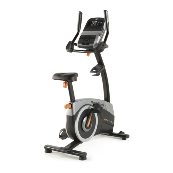
The GX 4.4 PRO exercise bike decal are shown on the front cover of this manual. provides an impressive selection of features designed... -
Page 6: Part Identification Chart
PART IDENTIFICATION CHART Use the drawings below to identify the small parts needed for assembly. The number in parentheses below each drawing is the key number of the part, from the PART LIST near the end of this manual. The number following the key number is the quantity needed for assembly. -
Page 7: Assembly
ASSEMBLY • Assembly requires two persons. • In addition to the included tool(s), assembly requires the following tools: • Place all parts in a cleared area and remove the one Phillips screwdriver packing materials. Do not dispose of the packing materials until you finish all assembly steps. - Page 8 3. Set a sturdy piece of packing material under the front of the Frame (1). Attach the Front Stabilizer (2) to the Frame (1) with two M10 x 98mm Screws (53). Then, remove the packing material. 4. With the help of a second person, raise the Upright (4) to the vertical position.
- Page 9 5. Attach the Accessory Tray (8) to the Upright (4) with an M6 x 50mm Screw (89). 6. Have a second person hold the Handlebar (5) near the Upright (4). See the inset drawing. Route the Upper Wire (87) through the Pivot Post (78) and the Pivot Bracket (71) as shown.
- Page 10 7. While a second person holds the Console (13) near the Pivot Bracket (71), connect the wires on the Console to the Upper Wire (87) and the Pulse Wires (61). Insert the excess wire downward through the Pivot Bracket (71). Do not insert the excess wire into the Console (13);...
- Page 11 9. Remove the Seat Knob (26) from the Seat Bracket (30) inside the Seat Carriage (24). Next, hold the Seat Carriage (24) on the Seat Post (6). Insert the Seat Knob (26) upward into the Seat Post, and tighten the Seat Knob into the Seat Bracket (30) inside the Seat Carriage.
- Page 12 11. Identify the Right Pedal (21). Using an adjustable wrench, firmly tighten the Right Pedal (21) clockwise into the Right Crank Arm (19). Firmly tighten the Left Pedal (not shown) counterclockwise into the Left Crank Arm (not shown). IMPORTANT: You must turn the Left Pedal counterclockwise to attach it.
-
Page 13: How To Use The Exercise Bike
HOW TO USE THE EXERCISE BIKE HOW TO PLUG IN THE POWER ADAPTER HOW TO ADJUST THE LATERAL POSITION OF THE SEAT IMPORTANT: If the exercise bike has been exposed to cold temperatures, allow it to warm to room To adjust the lateral temperature before you plug in the power adapter. - Page 14 CONSOLE DIAGRAM FEATURES OF THE CONSOLE The advanced console offers an array of features designed to make your workouts more effective and enjoyable. When you use the manual mode of the console, you can change the resistance of the pedals with the touch of a button.
- Page 15 HOW TO USE THE MANUAL MODE Calories per Hour (Cals/Hr)—This display will show the approximate number of calories you are 1. Turn on the console. burning per hour. Distance—This display will show the distance that Begin pedaling or press any button on the console to turn on the console.
- Page 16 Scan Mode and Priority rate, hold the handgrip heart rate monitor with your Mode—The calories and watts palms resting against the contacts. Avoid moving displays will appear in an your hands or gripping the contacts tightly. alternating cycle (scan mode). To select either the calories When your pulse is detected, your heart rate will or the watts display for continuous display (prior-...
- Page 17 HOW TO USE AN ONBOARD WORKOUT next segment, the resistance level and/or target speed will appear in the display to alert you. The 1. Turn on the console. resistance of the pedals will then change. Begin pedaling or press any button on the console As you exercise, keep your pedaling speed near to turn on the console.
- Page 18 HOW TO CONNECT YOUR TABLET TO THE 4. Record and track your workout information. CONSOLE Follow the instructions in the iFit Bluetooth Tablet The console supports BLUETOOTH connections to app to record and track your workout information. tablets via the iFit Bluetooth Tablet app and to compat- ible heart rate monitors.
- Page 19 HOW TO USE THE SOUND SYSTEM HOW TO CHANGE CONSOLE SETTINGS To play music or audio books through the console 1. Select the settings mode. sound system while you exercise, plug a 3.5 mm male to 3.5 mm male audio cable (not included) into the To select the settings mode, press the Settings jack on the console and into a jack on your personal button.
-
Page 20: Fcc Information
FCC INFORMATION This equipment has been tested and found to comply with the limits for a Class B digital device, pursuant to part 15 of the FCC Rules. These limits are designed to provide reasonable protection against harmful interference in a residential installation. This equipment generates, uses, and can radiate radio frequency energy and, if not installed and used in accordance with the instructions, may cause harmful interference to radio communications. -
Page 21: Maintenance And Troubleshooting
MAINTENANCE AND TROUBLESHOOTING MAINTENANCE HOW TO ADJUST THE DRIVE BELT Regular maintenance is important for optimal If the pedals slip while you are pedaling, even while the performance and to reduce wear. Inspect and properly resistance is adjusted to the highest setting, the drive belt may need to be adjusted. - Page 22 HOW TO ADJUST THE REED SWITCH Locate the Reed Switch (57). Rotate the Left Crank Arm (20) until a Magnet (55) is aligned with the Reed If the console does not display correct feedback, the Switch. Next, loosen the M5 x 16mm Flat Head Screw reed switch should be adjusted.
-
Page 23: Exercise Guidelines
EXERCISE GUIDELINES Burning Fat—To burn fat effectively, you must exer- WARNING: cise at a low intensity level for a sustained period of Before beginning this time. During the first few minutes of exercise, your or any exercise program, consult your physi- body uses carbohydrate calories for energy. - Page 24 SUGGESTED STRETCHES The correct form for several basic stretches is shown at the right. Move slowly as you stretch; never bounce. 1. Toe Touch Stretch Stand with your knees bent slightly and slowly bend forward from your hips. Allow your back and shoulders to relax as you reach down toward your toes as far as possible.
-
Page 25: Part List
PART LIST Model No. NTEX75016.0 R0916A Key No. Qty. Description Key No. Qty. Description Frame M8 x 18mm Screw Front Stabilizer Knob Nut Rear Stabilizer M8 x 76mm Bolt Upright J-bolt Handlebar #10 x 12mm Screw Seat Post M10 x 98mm Screw Rear Shield Cover Drive Belt Accessory Tray... -
Page 26: Exploded Drawing
EXPLODED DRAWING A Model No. NTEX75016.0 R0916A... - Page 27 EXPLODED DRAWING B Model No. NTEX75016.0 R0916A...
-
Page 28: Ordering Replacement Parts
ORDERING REPLACEMENT PARTS To order replacement parts, please see the front cover of this manual. To help us assist you, be prepared to provide the following information when contacting us: • the model number and serial number of the product (see the front cover of this manual) •...
Need help?
Do you have a question about the GX 4.4 PRO and is the answer not in the manual?
Questions and answers
Manual for Nordic TrackGXL 4 4 PPQ.Please