
Related Manuals for Miller Electric Subarc DC 650


Summary of Contents for Miller Electric Subarc DC 650
- Page 1 OM-236 684K 2012−07 Processes Multiprocess Welding Submerged (SAW) Welding Description Arc Welding Power Source Subarc DC 650/800 CE And Non-CE File: Submerged (SAW) Visit our website at www.MillerWelds.com...
- Page 2 ISO 9001 Quality System Standard. particular model are also provided. Miller Electric manufactures a full line of welders and welding related equipment. For information on other quality Miller products, contact your local Miller distributor to receive the latest full line catalog or individual specification sheets.
-
Page 3: Table Of Contents
TABLE OF CONTENTS SECTION 1 − SAFETY PRECAUTIONS - READ BEFORE USING ........1-1. -
Page 4: Declaration Of Conformity
DECLARATION OF CONFORMITY for European Community (CE marked) products. MILLER Electric Mfg. Co., 1635 Spencer Street, Appleton, WI 54914 U.S.A. declares that the product(s) identified in this declaration conform to the essential requirements and provisions of the stated Council Directive(s) and Standard(s). -
Page 5: Section 1 − Safety Precautions - Read Before Using
SECTION 1 − SAFETY PRECAUTIONS - READ BEFORE USING som 2011−10 Protect yourself and others from injury — read, follow, and save these important safety precautions and operating instructions. 1-1. Symbol Usage DANGER! − Indicates a hazardous situation which, if Indicates special instructions. - Page 6 D Remove stick electrode from holder or cut off welding wire at FUMES AND GASES can be hazardous. contact tip when not in use. D Wear oil-free protective garments such as leather gloves, heavy Welding produces fumes and gases. Breathing shirt, cuffless trousers, high shoes, and a cap.
-
Page 7: Additional Symbols For Installation, Operation, And Maintenance
1-3. Additional Symbols For Installation, Operation, And Maintenance FIRE OR EXPLOSION hazard. BATTERY EXPLOSION can injure. D Do not install or place unit on, over, or near D Do not use welder to charge batteries or jump combustible surfaces. start vehicles unless it has a battery charging feature designed for this purpose. -
Page 8: California Proposition 65 Warnings
1-4. California Proposition 65 Warnings Welding or cutting equipment produces fumes or gases This product contains chemicals, including lead, known to which contain chemicals known to the State of California to the state of California to cause cancer, birth defects, or other cause birth defects and, in some cases, cancer. -
Page 9: Section 2 − Consignes De Sécurité − Lire Avant Utilisation
SECTION 2 − CONSIGNES DE SÉCURITÉ − LIRE AVANT UTILISATION fre_som_2011−10 Pour écarter les risques de blessure pour vous−même et pour autrui — lire, appliquer et ranger en lieu sûr ces consignes relatives aux précautions de sécurité et au mode opératoire. 2-1. - Page 10 Il reste une TENSION DC NON NÉGLIGEABLE dans LE SOUDAGE peut provoquer un les sources de soudage onduleur UNE FOIS incendie ou une explosion. l’alimentation coupée. Le soudage effectué sur des conteneurs fermés tels D Arrêter les convertisseurs, débrancher le courant électrique et que des réservoirs, tambours ou des conduites peut décharger les condensateurs d’alimentation selon les instructions provoquer leur éclatement.
-
Page 11: Dangers Supplémentaires En Relation Avec L'installation, Le Fonctionnement Et La Maintenance
ACCUMULATIONS LES BOUTEILLES peuvent exploser risquent de provoquer des blessures si elles sont endommagées. ou même la mort. Les bouteilles de gaz comprimé contiennent du gaz sous haute pression. Si une bouteille est D Fermer l’alimentation du gaz comprimé en cas endommagée, elle peut exploser. -
Page 12: Proposition Californienne 65 Avertissements
Les PIÈCES MOBILES peuvent RAYONNEMENT HAUTE causer des blessures. FRÉQUENCE (H.F.) risque provoquer des interférences. D Ne pas s’approcher des organes mobiles. D Ne pas s’approcher des points de coincement D Le rayonnement haute fréquence (H.F.) peut tels que des rouleaux de commande. provoquer des interférences avec les équi- pements de radio−navigation et de com- LES FILS DE SOUDAGE peuvent... -
Page 13: Principales Normes De Sécurité
2-5. Principales normes de sécurité Safety in Welding, Cutting, and Allied Processes, ANSI Standard Z49.1, Spectrum Way, Suite 100, Ontario, Canada L4W 5NS (phone: is available as a free download from the American Welding Society at 800-463-6727, website: www.csa-international.org). http://www.aws.org or purchased from Global Engineering Documents Safe Practice For Occupational And Educational Eye And Face Protec- (phone: 1-877-413-5184, website: www.global.ihs.com). - Page 14 OM-236 684 Page 10...
-
Page 15: Section 3 − Definitions
SECTION 3 − DEFINITIONS 3-1. Additional Safety Symbols And Definitions Some symbols are found only on CE products. Warning! Watch Out! There are possible hazards as shown by the symbols. Safe1 2012−05 Wear dry insulating gloves. Do not touch electrode with bare hand. Do not wear wet or damaged gloves. Safe2 2012−05 Protect yourself from electric shock by insulating yourself from work and ground. - Page 16 Do not remove or paint over (cover) the label. Safe20 2012−05 Disconnect input plug or power before working on machine. Safe30 2012−05 Consult rating label for input power requirements. Safe34 2012−05 Read Owner’s Manual and inside labels for connection points and procedures. Í...
-
Page 17: Miscellaneous Symbols And Definitions
3-2. Miscellaneous Symbols And Definitions Some symbols are found only on CE products. Amperage/Voltage Gas Tungsten Arc Shielded Metal Arc Amperes Control−Panel Welding (GTAW) Welding (SMAW) Gas Metal Arc Temperature Wire Feeder Arc Force (DIG) Welding (GMAW) Output Circuit Breaker Remote Volts Positive High In-... -
Page 18: Section 4 − Installation
SECTION 4 − INSTALLATION 4-1. Important Information Regarding CE Products (Sold Within The EU) A. Information On Electromagnetic Fields (EMF) This equipment shall not be used by the general public as the EMF limits for the general public might be exceeded during welding. This equipment is built in accordance with EN 60974−1 and is intended to be used only in an occupational environment (where the general public access is prohibited or regulated in such a way as to be similar to occupational use) by an expert or an instructed person. -
Page 19: Duty Cycle And Overheating
4-4. Duty Cycle And Overheating Duty Cycle is percentage of 10 min- utes that unit can weld at rated load without overheating. If unit overheats, thermostat(s) opens, output stops, and cooling fan runs. Wait fifteen minutes for unit to cool. Reduce amperage or duty cycle before welding. -
Page 20: Selecting A Location
4-6. Selecting A Location Lifting Eye Lifting Forks Use lifting eye or lifting forks to move unit. If using lifting forks, extend forks beyond opposite side of unit. Movement Line Disconnect Device Locate unit near correct input power supply. Special installation may be required where gasoline or volatile liquids are present −... -
Page 21: Dimensions And Weights
4-7. Dimensions And Weights Dimensions 30 in. (762 mm) Including lift eye 23 in. (584 mm) 38 in. (965 mm) Including strain relief 35 in. (889 mm) 1-1/4 in. (32 mm) 4 Holes 21-1/8 in. (537 mm) 1-1/8 in. (29 mm) 7/16 in. -
Page 22: 115 Vac Receptacle And Supplementary Protectors
4-9. 115 VAC Receptacle And Supplementary Protectors Turn power before connecting to receptacle. 115 V 15 A AC Receptacle Power is shared between RC9 and Remote 14 receptacle RC8 (see Section 4-15). Supplementary Protector CB1 Supplementary Protector CB2 CB1 protects the 115 volts AC por- tion of RC8 and RC9 from overload. -
Page 23: Weld Output Terminals And Selecting Cable Sizes
4-11. Weld Output Terminals And Selecting Cable Sizes* NOTICE − The Total Cable Length in Weld Circuit (see table below) is the combined length of both weld cables. For example, if the power source is 100 ft (30 m) from the workpiece, the total cable length in the weld circuit is 200 ft (2 cables x 100 ft). Use the 200 ft (60 m) column to determine cable size. -
Page 24: Connecting Weld Output Cables
4-12. Connecting Weld Output Cables Tools Needed: 3/4 in. (19 mm) 803 778-B cable terminal and copper bar. Make Weld Cable Terminal Turn off power before connecting to sure that the surfaces of the weld cable weld output terminals. Copper Bar terminal and copper bar are clean. -
Page 25: Basic Sub Arc (Saw) Welding
4-13. Basic Sub Arc (SAW) Welding Customer must supply the following: power source, power source control cable, wire drive assembly, wire drive assembly cable, drive rolls, gun, welding wire, weld cables, remote voltage sense leads, and flux system for the desired application. A. - Page 26 B. Control Settings For Sub Arc (SAW) Welding Set switches as shown for remote con- trol. Turn on welding power source, flux system, wire drive assembly and HDC Sub Arc controller. When Control switch is in Remote position, Adjust control does not function. Set desired preset voltage on Sub Arc controller.
- Page 27 C. Remote Voltage Sensing Leads Placement Guidelines For A Single Arc (Required) Remote Voltage Sense Leads Welding Power Sense lead is affected by weld Source current. Due to voltage drops across work piece, arc voltage may be low, causing need for deviation from standard procedures.
- Page 28 D. Sensing Leads Placement Guidelines For Multiple Arcs Remote Voltage Lead Sense Leads Welding Power Source Current flow from lead affects trail sense. Current flow from trail affects lead sense. Remote Voltage Neither sense lead picks up the Sense Leads Lead Trail correct work voltage, causing...
-
Page 29: Flux Cored (Fcaw) Cable Connections
4-14. Flux Cored (FCAW) Cable Connections FCAW Gas Flowmeter/ Regulator Submerged INDUCTANCE (Gasless FCAW) − Turn Off power before making connections. Rear Of Wire Feeder For better performance for most (gas shielded) FCAW (DCEP) applications, it is recommended that weld output connections be made to the Low Inductance weld output ter- minal. -
Page 30: Remote 14 Receptacle Rc8 And Terminal Strip 1T Information
4-15. Remote 14 Receptacle RC8 And Terminal Strip 1T Information Socket Terminal Information 24 volts AC. Protected by supplementary protector CB2. 24 VOLTS AC Contact closure to A completes 24 volts AC contactor control circuit. Command reference; 0 to +10 volts DC (CC), +10 volts DC (CV). Remote control circuit common. -
Page 31: Connecting Remote Control
4-16. Connecting Remote Control Turn off power before con- necting a remote control. Remote 14 Receptacle RC8 Connect remote control to RC8, if plug does not fit, wire cord to terminal strip 1T. Turn Off and disconnect in- put power before opening terminal strip cover. -
Page 32: Electrical Service Guide
4-17. Electrical Service Guide Elec Serv 2011−08 Failure to follow these electrical service guide recommendations could create an electric shock or fire hazard. These recommenda- tions are for a dedicated circuit sized for the rated output and duty cycle of the welding power source. In dedicated circuit installations, the National Electrical Code (NEC) allows the receptacle or conductor rating to be less than the rating of the circuit protection device. - Page 33 Notes Work like a Pro! Pros weld and cut safely. Read the safety rules at the beginning of this manual. OM-236 684 Page 29...
-
Page 34: Connecting 3-Phase Input Power
4-19. Connecting 3-Phase Input Power = GND/PE Earth Ground IMPORTANT Input Contactor L1 (U) L2 (V) L3 (W) GND/ PE Earth Ground Tools Needed: 5/32 in. 3/8, 1/2 in. 3/8 in. input3 2012−05 − Ref. 803 766-C / 800 103-C / Ref. 801 116-A OM-236 684 Page 30... - Page 35 4-19. Connecting 3-Phase Input Power (Continued) applicable, use lugs of proper amperage Connect input conductors L1 (U), L2 (V) and Installation must meet all National capacity and correct hole size. L3 (W) to welding power source line and Local Codes − have only qualified terminals.
-
Page 36: Section 5 − Operation
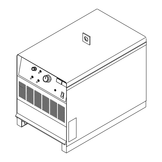
SECTION 5 − OPERATION 5-1. Controls (Non CE And CE Models) Ref. 230 863-A / Ref. 230 864-A Arc Force (Dig) Control Amperage/Voltage Adjustment Control Remote Amperage/Voltage Control Switch When Process Selector switch is in the Control increases SMAW short-circuit Constant Current position, turn control ... -
Page 37: Section 6 − Maintenance & Troubleshooting
SECTION 6 − MAINTENANCE & TROUBLESHOOTING 6-1. Routine Maintenance Disconnect and lockout/tagout input power before per- forming maintenance or troubleshooting procedures. n = Check Z = Change ~ = Clean l = Replace * To be done by Factory Authorized Service Agent Every Months l Unreadable Labels... -
Page 38: Troubleshooting
6-4. Troubleshooting Trouble Remedy No weld output; unit completely Place line disconnect device in On position (see Section 4-19). inoperative; pilot light PL1 off. Check for open line fuse(s), and replace if open (see Section 4-19). Check for proper input power connections (see Section 4-19). Check for proper jumper link position (see Section 4-18). - Page 39 Notes Work like a Pro! Pros weld and cut safely. Read the safety rules at the beginning of this manual. OM-236 684 Page 35...
-
Page 40: Section 7 − Electrical Diagram
SECTION 7 − ELECTRICAL DIAGRAM Figure 7-1. Circuit Diagram OM-236 684 Page 36... - Page 41 228 467-B OM-236 684 Page 37...
-
Page 42: Section 8 − Parts List
SECTION 8 − PARTS LIST Hardware is common and not available unless listed. 804 628--A Figure 8-1. Main Assembly (650 Model Illustrated) OM-236 684 Page 38... - Page 43 Item Dia. Part Mkgs. Description Quantity Figure 8-1. Main Assembly (652 Model Illustrated) ..... +179 432 PANEL, side ..........
- Page 44 ... Hardware is common and not available unless listed. 804 613-A Figure 8-2. Panel, Front w/Components (Fig 8-1 Item 30) Item Dia. Part Mkgs. Description Quantity Figure 8-2. Panel, Front w/Components (Fig 8-1 Item 28) .
- Page 45 Item Dia. Part Mkgs. Description Quantity Figure 8-2. Panel, Front w/Components (Fig 8-1 Item 28) (Continued) ..R4, R5 ..136 076 RESISTOR, ww fxd 30 w 200 ohm faston term .
- Page 46 Item Dia. Part Mkgs. Description Quantity Figure 8-3. Rectifier, Si Diode (Fig 8-1 Item 29) ..C7.12 ..048 420 CAPACITOR, cer disc .01uf 1000VDC ......
- Page 47 Item Dia. Part Mkgs. Description Quantity Figure 8-4. Panel, Rear w/Components (Fig 8-1 Item 18) ....173 283 CHAMBER, plenum 14 in ........
- Page 48 Notes...
- Page 49 Notes...
- Page 50 Notes...
- Page 51 LIMITED WARRANTY − Subject to the terms and conditions 90 Days — Parts Call below, Miller Electric Mfg. Co., Appleton, Wisconsin, warrants to its Accessory (Kits) 1-800-4-A-MILLER original retail purchaser that new Miller equipment sold after the...
- Page 52 Contact the Delivering Carrier to: File a claim for loss or damage during shipment. For assistance in filing or settling claims, contact your distributor and/or equipment manufacturer’s Transportation Department. ORIGINAL INSTRUCTIONS − PRINTED IN USA 2012 Miller Electric Mfg. Co. 2012−01...
Need help?
Do you have a question about the Subarc DC 650 and is the answer not in the manual?
Questions and answers