Table of Contents
Advertisement
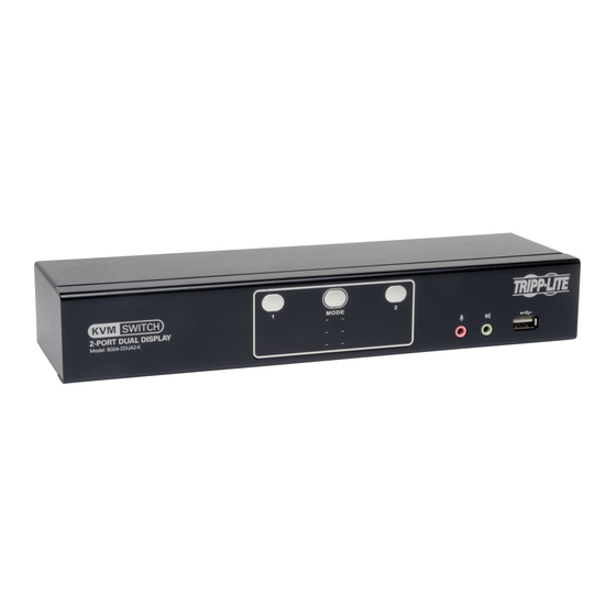
Dual Display DVI/USB KVM Switch
with Audio and Peripheral Sharing
Models: B004-2DUA2-K, B004-2DUA4-K
1111 W. 35th Street, Chicago, IL 60609 USA • www.tripplite.com/support
13-09-063-933242-EN.indd 1
Owner's Manual
Copyright © 2013 Tripp Lite. All rights reserved.
1
2
2
3
6
8
12
20
21
22
23
9/10/2013 4:45:00 PM
Advertisement
Table of Contents

Related Manuals for Tripp Lite B004-2DUA2-K


Summary of Contents for Tripp Lite B004-2DUA2-K
-
Page 1: Table Of Contents
System Requirements Features Safety Instructions Installation Basic Operation Firmware Upgrade Factory Default Settings Specifications Warranty and Warranty Registration 1111 W. 35th Street, Chicago, IL 60609 USA • www.tripplite.com/support Copyright © 2013 Tripp Lite. All rights reserved. 13-09-063-933242-EN.indd 1 9/10/2013 4:45:00 PM... -
Page 2: Package Contents
• 3.5 mm Mini Stereo microphone and speaker jacks (If using the microphone and speakers audio feature) *Requires an adapter, such as Tripp Lite’s P556-Series DVI to VGA adapter cables. Note that the included DVI cables and cable kits are DVI-D only, and cannot be converted to VGA using an adapter. **See the Quad-View Mode section of this manual for details... -
Page 3: Features
Features • 2- and 4-Port Dual Display DVI/USB KVM switch with 2.1 channel surround-sound audio and USB 2.0 peripheral sharing • Quad-View Mode allows computers with four DVI output ports to share KVM, audio and USB peripherals by connecting two Dual Display KVM switches together • Built-in 2-Port USB 2.0 hub allows USB devices to be shared amongst computers connected to the KVM switch • 3.5 mm Mini Stereo Speaker and Microphone jacks allow a single microphone to provide audio input to each of the connected computers, and let you listen to the audio output of each computer on a single set of speakers • Additional console audio jacks are conveniently located on the front panel of the KVM switch, making them ideal for use with IP phones • The KVM, USB and Audio can be switched independently of each other. For example, you can access one computer while at the same time listening to audio from another computer and printing from a third computer • Features mouse port switching functionality*, which allows users accessing the KVM switch with a scroll mouse to switch between ports by double-clicking the mouse’s scroll wheel... - Page 4 Features Front Panel No. Component Description Pressing one of the port selection pushbuttons will bring Port Selection Pushbuttons the focus of one of the following to the corresponding port; KVM only, Audio only, USB only, or KVM, Audio and USB simultaneously. What functionality is switched is determined by the Mode Selection Pushbutton (see below). Pressing and holding pushbuttons 1 and 2 simultaneously for more than 2 seconds will initiate an auto scan. On the B004-2DUA4-K, pressing and holding pushbuttons 3 and 4 simultaneously for more than 2 seconds will perform a USB keyboard/mouse reset.
- Page 5 Features Back Panel No. Component Description This port is used to connect two Dual Display KVM switches Quad-View Mode Port together via standard Cat5e/6 cable. When connected together, computers with four DVI output ports can share KVM, audio and USB peripherals (see the Quad-View Mode section in this manual for details). This switch determines which unit is the Client and which is the Quad-View Mode Switch Host in a Quad-View Mode installation (see the Quad-View Mode section in this manual for details). USB 2.0 USB 2.0 devices (flash drives, printers, scanners, etc.) can be plugged into this port and shared between the connected...
-
Page 6: Safety Instructions
Safety Instructions • Read all of these instructions. Save them for future reference. • Follow all warnings and instructions marked on the device. • Do not place the device on any unstable surface (cart, stand, table, etc.). If the device falls, serious damage will result. • Do not use the device near water. • Do not place the device near, or over, radiators or heat registers. The device cabinet is provided with slots and openings to allow for adequate ventilation. To ensure reliable operation, and to protect against overheating, these openings must never be blocked or covered. • The device should never be placed on a soft surface (bed, sofa, rug, etc.) as this will block its ventilation openings. Likewise, the device should not be placed in a built in enclosure unless adequate ventilation has been provided. • Never spill liquid of any kind on the device. • Unplug the device from the wall outlet before cleaning. Do not use liquid or aerosol cleaners. Use a damp cloth for cleaning. • The device should be operated from the type of power source indicated on the marking label. If you are not sure of the type of power available, consult your dealer or local power company. • Do not allow anything to rest on the power cord or cables. Route the power cord and cables so that they cannot be stepped on or tripped over. • If an extension cord is used with this device make sure that the total of the ampere ratings of all products used on this cord does not exceed the extension cord ampere rating. Make sure that the total of all products plugged into the wall outlet does not exceed 15 amperes. • Position system cables and power cables carefully; be sure that nothing rests on any cables. - Page 7 Safety Instructions • If the following conditions occur, unplug the device from the wall outlet and bring it to qualified service personnel for repair. o The power cord or plug has become damaged or frayed. o Liquid has been spilled into the device. o The device has been exposed to rain or water. o The device has been dropped, or the cabinet has been damaged. o The device exhibits a distinct change in performance, indicating a need for service. o The device does not operate normally when the operating instructions are followed. • Only adjust those controls that are covered in the operating instructions. Improper adjustment of other controls may result in damage that will require extensive work by a qualified technician to repair. • Use of this equipment in life support applications where failure of this equipment can reasonably be expected to cause the failure of the life support equipment or to significantly affect its safety or effectiveness is not recommended. Do not use this equipment in the presence of a flammable anesthetic mixture with air, oxygen or nitrous oxide. 13-09-063-933242-EN.indd 7 9/10/2013 4:45:01 PM...
-
Page 8: Installation
1. Before making any connections, make sure that power to all devices being connected to the KVM switch is turned off. Unplug the power cords of any computers that have the Keyboard Power On function. 2. The diagram below shows the B004-2DUA4-K installation. Installation for the B004-2DUA2-K is the same except there are fewer ports. - Page 9 Installation Connect a DVI cable to the DVI B port on the back of the KVM, and then into a DVI port on the computer being added to the installation. Note: The B004-2DUA2-K and B004-2DUA4-K come with 6 ft. DVI-D Dual Link Cables. If you need a longer cable, you will have to purchase a separate P560-Series (DVI-D Dual-Link) or P561-Series (DVI-D Single-Link) cable of the appropriate length. Repeat steps 6 through 8 for each additional computer you are adding to the installation. Connect the included power supply to the KVM switch, and then plug it into an appropriate power source. To help protect your system from sudden transient increases and decreases in electrical power, it is recommended that you plug your devices into a Tripp Lite surge suppressor, line conditioner, or uninterruptible power supply (UPS). Turn on the power to all connected devices. 13-09-063-933242-EN.indd 9 9/10/2013 4:45:02 PM...
- Page 10 2. In Quad-View Mode, the keyboard and mouse console ports on the Client KVM are disabled, as are the front- panel pushbuttons of the Client KVM. 3. The diagram below shows the B004-2DUA4-K installation. Installation for the B004-2DUA2-K is the same except there are fewer ports.
- Page 11 Optional – Connect your USB device(s) to the USB 2.0 hub port(s) on the front and back of the Host KVM switch. Optional – Connect your USB device(s) to the USB 2.0 hub port(s) on the front and back of the Client KVM switch. Note: The USB ports on the back of the Client KVM must be connected to the computers for these ports to work. See step 16. Connect the end of the KVM Cable Kit that includes the USB Type B Male connector to an available set of computer ports on the back panel of the Host KVM switch. Connect the DVI connector to the DVI A port, and the USB and 3.5 mm connectors to the corresponding USB and 3.5 mm ports. Connect the other end of the KVM Cable Kit to the corresponding ports on the computer you wish to add to the installation. Note: The B004-2DUA2-K and B004-2DUA4-K come with 6 ft. Cable Kits. If you need a longer cable, you will have to purchase a separate P759-Series DVI/USB + Audio KVM Cable Kit of the appropriate length. Connect a DVI cable to the DVI B port on the back of the Host KVM switch, and then into a DVI port on the computer being added to the installation. Note: The B004-2DUA2-K and B004-2DUA4-K come with 6 ft. DVI-D Dual Link Cables. If you need a longer cable, you will have to purchase a separate P560-Series (DVI-D Dual-Link) or P561-Series (DVI-D Single-Link) cable of the appropriate length. Connect a DVI cable to the DVI A port on the back of the Client KVM switch, and then into a DVI port on the computer being added to the installation. Connect a DVI cable to the DVI B port on the back of the Client KVM switch, and then into a DVI port on the computer being added to the installation.
-
Page 12: Basic Operation
When enabled, the Mouse Port Switching Functionality allows users with scroll mice to simultaneously switch the focus of the KVM, Audio and USB between ports by double-clicking the scroll wheel on their mouse. When used, ports will be accessed in sequential order. (e.g. port 1 will switch to port 2; port 2 to port 3, and so on). As this function is disabled by default, you have to enable it via hotkey command (See Mouse Port Switching in the Hotkeys section of this manual for details). For Mouse Port Switching Functionality to work, Mouse Emulation must be turned on. Hotkeys Hotkeys allow you to switch functionality focus between ports using only the keyboard, as well as configure KVM switch settings. The following section describes the hotkey functionality available for the B004-2DUA2-K and B004-2DUA4-K. 13-09-063-933242-EN.indd 12 9/10/2013 4:45:02 PM... - Page 13 Basic Operation Port Switching Hotkeys To switch functionality between ports, a keyboard hotkey command is entered that determines what port is accessed and which functionality is assigned to it. This command starts by pressing [Scroll Lock] [Scroll Lock] or [Ctrl] [Ctrl]. [Scroll Lock] [Scroll Lock] is used by default. To toggle between these two, see Alternate Port Switching Hotkey Command in the Hotkey Setting Mode section of this manual. The table below contains the Port Switching Hotkeys used to determine what port is accessed and which functionality is assigned to it.
- Page 14 Alternate Port Switching Hotkey Command By default, the hotkey proceeding sequence used in Port Switching Hotkeys is [Scroll Lock] [Scroll Lock]. To toggle between [Scroll Lock] [Scroll Lock] and [Ctrl] [Ctrl], do the following. 1. Activate Hotkey Setting Mode using the aforementioned command 2. Press and release the [T] key Keyboard Operating System The B004-2DUA2-K and B004-2DUA4-K default keyboard configuration is for use with PC compatible keyboards. If you have a Mac or Sun computer, you can enable the KVM to emulate Mac or Sun keyboard commands. When enabled, your PC compatible keyboard can be used to perform commands specific to Mac or Sun (See the Keyboard Emulation section in this manual for details). To set the Keyboard Operating System, do the following. 1. Navigate to the port whose Keyboard Operating System setting you wish to change 2.
- Page 15 1. Activate Hotkey Setting Mode using the aforementioned command 2. Press and release the [x] key and then press and release the [Enter] key Firmware Upgrade Mode The B004-2DUA2-K and B004-2DUA4-K firmware can be upgraded as updates become available on Tripp Lite’s website (See the Firmware Upgrade section in this manual for details). In order to perform a firmware upgrade, Firmware Upgrade Mode must first be initiated. To initiate Firmware Upgrade Mode, do the following. 1. Activate Hotkey Setting Mode using the aforementioned command 2. Key in the text “upgrade”...
- Page 16 Basic Operation Power on Detection By default, the KVM is set to recognize when a connected computer is powered off, at which time it automatically switches to the next powered on port. To turn Power on Detection on/off, do the following. 1. Activate Hotkey Setting Mode using the aforementioned command 2. Press and release the [E] key Video Sync Video Sync allows the KVM to store the monitor’s EDID (Extended Display Identification Data), which helps to ensure optimal video settings are being used. To initiate a Video Sync, do the following. 1. Activate Hotkey Setting Mode using the aforementioned command 2. Press and release the [D] key Keyboard Emulation By default, Keyboard Emulation is enabled. To toggle keyboard emulation on/off, do the following.
- Page 17 Basic Operation Pushbutton 1 and 2 Command By default, pressing pushbuttons 1 and 2 at the same time for two seconds will initiate Auto Scan Mode, but you can set it to perform any Hotkey Setting Mode command that you want. The Restore Default Settings, Disable Port Switching Hotkeys, and Firmware Upgrade Mode commands cannot be used. To set the Pushbutton 1 and 2 Command, do the following. 1. Activate Hotkey Setting Mode using the aforementioned command 2. Press and release the [C] key 3. Perform the command that you wish to set. (e.g. Press and release the [W] key to set the Pushbutton 1 and 2 Command to turn Mouse Port Switching Functionality on/off.
-
Page 18: Mac Keyboard Emulation
Basic Operation Hotkey Setting Mode Command Summary Table Action Hotkey Command Activate Hotkey Setting Mode Press and hold the [Num Lock] key, press and release the minus [-] key, release the [Num Lock] key. Change Hotkey Setting Mode Activate Hotkey Setting Mode, [H] activation command to [Ctrl] [F12] Change the Port Switching Hotkey Activate Hotkey Setting Mode, [T] Command to [Ctrl] [Ctrl] Change the Keyboard Operating Activate Hotkey Setting Mode, [F2] (for Mac), [F3] System (for Sun), or [F10] (for Auto-Detect) -
Page 19: Sun Keyboard Emulation
Basic Operation Sun Keyboard Emulation The PC compatible (101/104 key) keyboard can emulate the functions of the Sun keyboard using the PC keystrokes in the table below. Note: When more than one key is required on the PC Keyboard to emulate the Sun keyboard, press and release the first key, and then press and release the second key. PC Keyboard Sun Keyboard PC Keyboard Sun Keyboard... -
Page 20: Firmware Upgrade
Firmware Upgrade Firmware Upgrade Utility As firmware upgrades become available, they can be found on the internet at www.tripplite.com/support. The Firmware Upgrade Utility comes with the firmware upgrade file. Firmware upgrades cannot be performed simultaneously when in Quad-View Mode. KVMs in Quad-View mode will need to be disconnected from each other, switched to the Host position, and upgraded separately. To upgrade the firmware of your KVM switch, follow the steps below: 1. From a computer connected to your KVM switch, go to www.tripplite.com/support to obtain the firmware upgrade for your KVM switch, and save it to your computer. 2. Shut down all of the computers connected to the KVM switch, except for the computer that you downloaded the firmware upgrade to. 3. Invoke Firmware Upgrade Mode via the Firmware Upgrade hotkey command. (See Firmware Upgrade Mode in the Hotkey Setting Mode section of this manual for details.) 4. On the computer the firmware upgrade file is saved to, run the Firmware Upgrade Utility file by double-clicking on it or by opening up a command line and typing in the... -
Page 21: Factory Default Settings
Factory Default Settings Setting Default Port Switching Hotkey Command [Scroll Lock], [Scroll Lock] Hotkey Setting Mode Activation Command [Num Lock], [-] Keyboard Operating System Auto-Detect Hotkey Beeper Port Switching Hotkeys Enabled Keyboard Emulation Enabled Mouse Emulation Enabled Mouse Switching Function Disabled Power on Detection Enabled SPC Mode Disabled Pushbutton 1 and 2 Command Auto Scan Initiation Pushbutton 3 and 4 Command USB Keyboard/Mouse Reset 13-09-063-933242-EN.indd 21 9/10/2013 4:45:03 PM... -
Page 22: Specifications
It is only available when using a mouse with a scroll wheel. **The B004-2DUA2-K and B004-2DUA4-K include 2 sets of Speaker/Mic ports; (2) 3.5mm jacks on the front and (2) 3.5mm jacks on the back. The front panel ports take priority over the back panel. -
Page 23: Warranty And Warranty Registration
EXCEPT AS PROVIDED ABOVE, IN NO EVENT WILL TRIPP LITE BE LIABLE FOR DIRECT, INDIRECT, SPECIAL, INCIDENTAL OR CONSEQUENTIAL DAMAGES ARISING OUT OF THE USE OF THIS PRODUCT, EVEN IF ADVISED OF THE POSSIBILITY OF SUCH DAMAGE. Specifically, TRIPP LITE is not liable for any costs, such as lost profits or revenue, loss of equipment, loss of use of equipment, loss of software, loss of data, costs of substitutes, claims by third parties, or otherwise. WARRANTY REGISTRATION Visit www.tripplite.com/warranty today to register the warranty for your new Tripp Lite product. You’ll be automatically entered into a drawing for a chance to win a FREE Tripp Lite product!* * No purchase necessary. Void where prohibited. Some restrictions apply. See website for details. WEEE Compliance Information for Tripp Lite Customers and Recyclers (European Union) Under the Waste Electrical and Electronic Equipment (WEEE) Directive and implementing regulations, when customers buy new electrical and electronic equipment from Tripp Lite they are entitled to: • Send old equipment for recycling on a one-for-one, like-for-like basis (this varies depending on the country) • Send the new equipment back for recycling when this ultimately becomes waste FCC Notice, Class B This device complies with part 15 of the FCC Rules. Operation is subject to the following two conditions: (1) This device may not cause harmful interference, and (2) this device must accept any interference received, including interference that may cause undesired operation. Note: This equipment has been tested and found to comply with the limits for a Class B digital device, pursuant to part 15 of the FCC Rules. These limits are designed to provide reasonable protection against harmful interference... - Page 24 1111 W. 35th Street, Chicago, IL 60609 USA • www.tripplite.com/support 13-09-063 • 93-3242_revB 13-09-063-933242-EN.indd 24 9/10/2013 4:45:03 PM...
Need help?
Do you have a question about the B004-2DUA2-K and is the answer not in the manual?
Questions and answers