Table of Contents
Advertisement
Available languages
Available languages
OPERATOR'S MANUAL
MANUEL D'UTILISATION
MANUAL DEL OPERADOR
5/8 in. HAMMER DRILL
PERCEUSE À PERCUSSION
DE 16 mm (5/8 po)
TALADRO DE PERCUSIÓN
DE 16 mm (5/8 pulg.)
D620H
INCLUDES: Hammer Drill, Auxiliary Handle
Assembly with Depth Stop Rod, Chuck
Key, Chuck Key Strap, Operator's Manual
****************
TABLE OF CONTENTS
Warnings .........................................2-3
Hammer Drill Safety Warnings ........... 3
Symbols ..............................................4
Electrical .............................................5
Features ..............................................6
Assembly .........................................6-7
Operation .........................................7-9
Maintenance ..................................... 10
Figure Numbers (Illustrations) ......11-12
Parts Ordering / Service ..... Back Page
WARNING:
To reduce the
risk of injury, the user must read and
understand the operator's manual
before using this product.
SAVE THIS MANUAL FOR
FUTURE REFERENCE
INCLUT : Perceuse à percussion, poignée
auxiliaire et tige de butée de profondeur, clé
de mandrin, porte-clé du mandrin, manuel
d'utilisation
****************
TABLE DES MATIÈRES
aux outils électriques ......................2-3
relatifs perceuse à percussion ........... 3
Symboles ............................................4
Caractéristiques électriques ............... 5
Caractéristiques ................................. 6
Assemblage .....................................6-7
Utilisation .........................................7-9
Entretien ...........................................10
Figure numéros (illustrations) ......11-12
Commande de pièces/
réparation ..........................Page arrière
AVERTISSEMENT :
réduire les risques de blessures,
l'utilisateur doit lire et veiller à bien
comprendre le manuel d'utilisation
avant d'employer ce produit.
CONSERVER CE MANUEL
POUR FUTURE RÉFÉRENCE
INCLUYE: Taladro de percusión, mango
auxiliar con barra limitadora de profundidad,
llave del portabrocas, almacenamiento de la
llave del portabrocas, manual del operador
****************
ÍNDICE DE CONTENIDO
Advertencias de seguridad
para herramientas eléctricas ...........2-3
Advertencias de seguridad
taladro de percusión .......................... 3
Símbolos ............................................4
Aspectos eléctricos ............................ 5
Características ................................... 6
Armado ............................................6-7
Funcionamiento ...............................7-9
Mantenimiento .................................. 10
Figura numeras (ilustraciones) ....11-12
Pedidos de piezas /
Servicio ......................... Pág. posterior
ADVERTENCIA:
Pour
el riesgo de lesiones, el usuario debe
leer y comprender el manual del
operador antes de usar este producto.
GUARDE ESTE MANUAL
PARA FUTURAS CONSULTAS
Para reducir
Advertisement
Table of Contents

Related Manuals for Ryobi D620H


Summary of Contents for Ryobi D620H
-
Page 1: Table Of Contents
PERCEUSE À PERCUSSION DE 16 mm (5/8 po) TALADRO DE PERCUSIÓN DE 16 mm (5/8 pulg.) D620H INCLUDES: Hammer Drill, Auxiliary Handle INCLUT : Perceuse à percussion, poignée INCLUYE: Taladro de percusión, mango auxiliaire et tige de butée de profondeur, clé... -
Page 2: General Power Tool Safety Warnings
GENERAL POWER TOOL SAFETY WARNINGS Prevent unintentional starting. Ensure the switch is in the off-position before connecting to power source WARNING and/or battery pack, picking up or carrying the tool. Read all safety warnings and all instructions. Failure to Carrying power tools with your finger on the switch or follow the warnings and instructions may result in electric energising power tools that have the switch on invites... -
Page 3: Hammer Drill Safety Warnings
GENERAL POWER TOOL SAFETY WARNINGS Use the power tool, accessories and tool bits etc. When servicing a power tool, use only identical in accordance with these instructions, taking into replacement parts. Follow instructions in the Main- account the working conditions and the work to be tenance section of this manual. -
Page 4: Symbols
SYMBOLS The following signal words and meanings are intended to explain the levels of risk associated with this product. SYMBOL SIGNAL MEANING Indicates an imminently hazardous situation, which, if not avoided, will result DANGER: in death or serious injury. Indicates a potentially hazardous situation, which, if not avoided, could result WARNING: in death or serious injury. -
Page 5: Electrical
ELECTRICAL DOUBLE INSULATION EXTENSION CORDS Double insulation is a concept in safety in electric pow- When using a power tool at a considerable distance from er tools, which eliminates the need for the usual three- a power source, be sure to use an extension cord that has wire grounded power cord. -
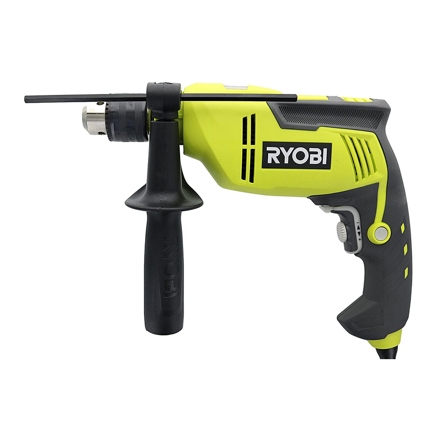
Page 6: Features
FEATURES PRODUCT SPECIFICATIONS Chuck Capacity ............1/2 in. Switch ......Variable Speed Reversible (VSR) Drilling Capacity: Blows Per Minute ........0-43,000 BPM Concrete ..............5/8 in. No Load Speed ........0-2,700 r/min. (RPM) Metal ..............1/2 in. Input .......120 V, AC only, 60 Hz, 6.2 Amps KNOW YOUR HAMMER DRILL DEPTH STOP ROD See Figure 1, page 11. -
Page 7: Operation
ASSEMBLY Securely tighten by turning the auxiliary handle clockwise. AUXILIARY HANDLE ASSEMBLY NOTE: Be sure the auxiliary handle is securely tightened See Figure 2, page 11. against the depth stop rod clamp. This secures the depth stop rod at the desired depth of cut. It also secures the WARNING: auxiliary handle. - Page 8 OPERATION Push in and hold the lock-on button, located on the side WARNING: of the handle. Make sure to insert the drill bit straight into the chuck Release the switch trigger. jaws. Do not insert the drill bit into the chuck jaws at ...
- Page 9 OPERATION WOOD AND METAL DRILLING NOTE: The hammer drill has not been designed for reverse hammering. For maximum performance, use high speed steel bits for Use carbide-tipped bits and select hammer mode when wood or metal drilling. Select drilling mode. Begin drilling drilling in hard materials such as brick, tile, concrete, etc.
-
Page 10: Maintenance
MAINTENANCE Electric tools used on fiberglass material, wallboard, WARNING: spackling compounds, or plaster are subject to acceler- ated wear and possible premature failure because the When servicing, use only identical replacement parts. fiberglass chips and grindings are highly abrasive to bear- Use of any other parts could create a hazard or cause ings, brushes, commutators, etc. -
Page 11: Règles De Sécurité Relatives Aux Outils Électriques
RÈGLES DE SÉCURITÉ RELATIVES AUX OUTILS ÉLECTRIQUES SÉCURITÉ PERSONNELLE AVERTISSEMENT Rester attentif, prêter attention au travail et faire preuve de bon sens lors de l’utilisation de tout outil électrique. Lire tous les avertissements et toutes les instructions. Ne pas utiliser cet outil en état de fatigue ou sous Ne pas suivre l’ensemble des avertissements et des l’influence de l’alcool, de drogues ou de médicaments. -
Page 12: Avertissements De Sécurité Relatifs Perceuse À Percussion
RÈGLES DE SÉCURITÉ RELATIVES AUX OUTILS ÉLECTRIQUES Ranger les outils motorisés hors de la portée des enfants Utiliser l’outil, les accessoires et embouts, etc. et ne laisser personne n’étant pas familiarisé avec l’outil conformément à ces instrutions pour les applications pour lesquelles ils sont conçus, en tenant compte des ou ces instructions utiliser l’outil. -
Page 13: Symboles
SYMBOLES Les termes de mise en garde suivants et leur signification ont pour but d’expliquer le degré de risques associé à l’utilisation de ce produit. SYMBOLE SIGNAL SIGNIFICATION Indique une situation extrêmement dangereuse qui, si elle n’est pas évitée, aura DANGER : pour conséquences des blessures graves ou mortelles. -
Page 14: Caractéristiques Électriques
CARACTÉRISTIQUES ÉLECTRIQUES DOUBLE ISOLATION CORDONS PROLONGATEURS La double isolation est un dispositif de sécurité utilisé sur les Lors de l’utilisation d’un outil électrique à grande distance outils à moteur électriques, éliminant le besoin de cordon d’une prise secteur, veiller à utiliser un cordon prolongateur d’alimentation habituel à... -
Page 15: Caractéristiques
CARACTÉRISTIQUES SPÉCIFICATIONS DU PRODUIT Capacité du mandrin ........13 mm (1/2 po) Gâchette ......Vitesse variable réversible (VSR) Capacité de perçage : Golpes por minuto ........0-43 000 CPM Béton ............16 mm (5/8 po) Vitesse à vide ........0 à 2 700 r/min (RPM) Métal ............13 mm (1/2 po) Alimentation.... -
Page 16: Utilisation
ASSEMBLAGE POIGNÉE AUXILIAIRE Resserrer bien la poignée en la tournant dans le sens horaire. Voir la figure 2, page 11. NOTE : S’assurer que la poignée auxiliaire est bien serrée contre le collier de la tige de butée de profondeur. Ceci AVERTISSEMENT : maintient la tige de butée à... - Page 17 UTILISATION Resserrer fermement les mors sur le foret au moyen de Si la fonction de verrouillage est engagée pendant l’utilisation la clé à mandrin fournie. et la perceuse accidentellement débranchée, désengager le verrouillage immédiatement. Retirer la clé du mandrin. RETRAIT DU FORET AVERTISSEMENT : Voir la figure...
- Page 18 UTILISATION Utiliser des forets à pointe carbure et sélectionner le mode PERÇAGE DU BOIS ET DU METAL de percussion pour le perçage des matériaux durs, tels que Pour une performance optimale, utiliser des forets en acier la brique, le carrelage, le béton, etc. haute vitesse pour le perçage du bois ou or métal.
-
Page 19: Entretien
ENTRETIEN Les outils électriques utilisés sur la fibre de verre, le AVERTISSEMENT : placoplâtre, les mastics de bouchage ou le plâtre s’usent plus vite et sont susceptibles de défaillance prématurée, car Utiliser exclusivement des pièces identiques à celles les particules et les éclats de fibre de verre sont fortement d’origine pour les réparations. - Page 20 ADVERTENCIAS DE SEGURIDAD PARA HERRAMIENTAS ELÉCTRICAS SEGURIDAD PERSONAL ADVERTENCIA Permanezca alerta, preste atención a lo que esté haciendo y aplique el sentido común al utilizar herramientas eléctricas. Lea todas las advertencias de seguridad y las No utilice la herramienta eléctrica si está cansado o se instrucciones.
- Page 21 ADVERTENCIAS DE SEGURIDAD PARA HERRAMIENTAS ELÉCTRICAS ajuste, cambiarle accesorios o guardarla. Tales medidas Utilice la herramienta eléctrica, los accesorios y brocas, preventivas de seguridad reducen el riesgo de poner en marcha hojas y cuchillas de corte, ruedas de esmeril, etc. de accidentalmente la herramienta.
- Page 22 SÍMBOLOS Las siguientes palabras de señalización y sus significados tienen el objeto de explicar los niveles de riesgo relacionados con este producto. SÍMBOLO SEÑAL SIGNIFICADO Indica una situación peligrosa inminente, la cual, si no se evita, causará la muerte PELIGRO: o lesiones serias.
- Page 23 ASPECTOS ELÉCTRICOS DOBLE AISLAMIENTO CORDONES DE EXTENSIÓN El doble aislamiento es una característica de seguridad de Al utilizar una herramienta eléctrica a una distancia las herramientas eléctricas, la cual elimina la necesidad considerable de la fuente de voltaje, asegúrese de utilizar de usar el típico cordón eléctrico de tres conductores con un cordón de extensión con la suficiente capacidad para conexión a tierra.
- Page 24 CARACTERÍSTICAS ESPECIFICACIONES DEL PRODUCTO Capacidad del portabrocas ......13 mm (1/2 pulg.) Interruptor .......Velocidad variable e invertible (VSR) Capacidad de taladrar: Golpes por minuto ........... 0-43 000 GPM Concreto ..........16 mm (5/8 pulg.) Velocidad en vacío ........0-2 700 r/min (RPM) Metal ............
- Page 25 ARMADO CONJUNTO DE MANGO AUXILIAR NOTA: Asegúrese de que el mango auxiliar quede firmemente apretado contra la abrazadera de la barra Vea la figura 2, página 11. limitadora de profundidad. De esta manera se ajusta la barra limitadora de profundidad a la profundidad de taladrado ADVERTENCIA: deseada.
- Page 26 FUNCIONAMIENTO Apriete firmemente la broca en las mordazas con la llave Si el seguro de encendido está puesto al usar el taladro, y éste suministrada para el portabrocas. se desconecta accidentalmente del suministro de voltaje, quite el seguro de encendido de inmediato. Retire la llave del portabrocas.
- Page 27 FUNCIONAMIENTO TALADRADO EN MADERA Y EN METAL Seleccione el modo de taladrado normal al taladrar en materiales blandos con brocas helicoidales, sierras cilíndricas, etc. Para obtener un desempeño óptimo de la unidad, utilice brocas de acero de alta velocidad para taladrado en madera. o en TALADRAD/INTRODUCCIÓN DE TORNILLOS metal.
- Page 28 MANTENIMIENTO Las herramientas eléctricas que se utilizan en materiales de ADVERTENCIA: fibra de vidrio, paneles de yeso para paredes, compuestos de resanar o yeso, están sujetas a desgaste acelerado y posible Al dar servicio a la unidad, utilice sólo piezas de repuesto fallo prematuro porque las partículas y limaduras de fibra de idénticas.
- Page 29 Fig. 1 A - Drilling/hammer mode selector (sélecteur E - Switch trigger (gachette, gatillo del interruptor) H - Variable speed dial (cadran à vitesse variable, de mode rotation / percussion, selector de F - Direction of rotation selector (forward/reverse) dial de velocidad variable) taladro/percusión) [sélecteur de sens de rotation (avant / arrière), I - Power cord (cordon d’alimentation, cordón de...
- Page 30 Fig. 5 Fig. 9 Fig. 7 A - Hammer mode (mode percussion, modo percusión) A - Direction of rotation selector (forward/reverse) WRONG / INCORRECT / FORMA INCORRECTA B - Drilling mode (mode perçage, modo taladro) [sélecteur de sens de rotation (avant / arrière), C - Drilling/hammer mode selector (sélecteur selector de sentido de rotación (adelante/ Fig.
- Page 31 NOTES / NOTAS...
- Page 32 • HOW TO OBTAIN CUSTOMER OR TECHNICAL SUPPORT: To obtain Customer or Technical Support please contact us at 1-800-525-2579. RYOBI is a registered trademark of Ryobi Limited and is used pursuant to a license granted by Ryobi Limited. • PIÈCES ET SERVICE Avant de faire la demande de service ou l’achat de pièces de remplacement, veuillez obtenir le numéro de série du modèle à...
Need help?
Do you have a question about the D620H and is the answer not in the manual?
Questions and answers